HAL Id: hal-00908095
https://hal.inria.fr/hal-00908095
Submitted on 22 Nov 2013
HAL is a multi-disciplinary open access archive for the deposit and dissemination of sci-entific research documents, whether they are pub-lished or not. The documents may come from
L’archive ouverte pluridisciplinaire HAL, est destinée au dépôt et à la diffusion de documents scientifiques de niveau recherche, publiés ou non, émanant des établissements d’enseignement et de
An experiment with reactive data-flow tasking in active
robot vision
Eric Rutten, Eric Marchand, François Chaumette
To cite this version:
Eric Rutten, Eric Marchand, François Chaumette. An experiment with reactive data-flow task-ing in active robot vision. Software: Practice and Experience, Wiley, 1997, 27 (5), pp.599-621. �10.1002/(SICI)1097-024X(199705)27:53.0.CO;2-K�. �hal-00908095�
An experiment with reactive data-flow tasking
in active robot vision
Eric Rutten, Eric Marchand, Franc¸ois Chaumette
IRISA / INRIA - Rennes, F-35042 RENNES, France
fax: (+33) 99.84.71.71
e-mail:
{rutten, marchand, chaumette}@irisa.fr
Summary
We present an experiment of the synchronous approach to reactive systems programming, and particularly the SIGNAL language, ap-plied to a significant problem in robot vision: active visual recon-struction. This application consists of the specification of a system dealing with various domains such as robot control, computer vi-sion and transitions between different modes of control. It illustrates the adequacy in such domains of SIGNAL, a data flow programming language and environment. The SIGNALprogramming environment features tools for formal specification, analysis, consistency check-ing and code generation. SIGNAL and its language-level extension for task preemption SIGNALGT˙ι are used at the different levels of the application: data-flow function for the camera motion control (vi-sual servoing), reconstruction method (in parallel to vi(vi-sual servoing, involving the dynamical processes), and reconstruction of complex scenes (with transitions between several robotics tasks). The com-bination of these levels constitutes a hybrid behavior with (sampled) continuous and discrete transitions. These techniques are validated experimentally by an implementation on a robotic cell.
Keywords: formal specification methods, reactive systems, data flow, task preemption, robotics, active vision.
1
An experiment with S
IGNAL
in robot vision
The synchronous methodology. This paper presents the application in active robot vision of the synchronous approach to reactive real time systems [4], and particularly of the language SIGNAL. Reactive systems are characterized by the fact that their pace is determined by their environment [14]. Their behavior is modelled as a discrete event system, in a way related to the works of Ramadge and Wonham [23]. An interpretation of the synchrony hypothesis is that all the relevant values involved in a computation (input, output and internal) are present simultaneously within the single instant of logical time when the system reacts to its input. In other words, it is valid if the system can be proved to react rapidly enough to perceive all relevant external events. It is an abstraction of the com-monly used infinite loop of automatic controllers (input acquisition, computation, output return). This form of synchrony is however a realistic abstraction, as it is actually present e.g. in digital hardware (all computations are performed within a clock cycle), and in control theory (a global time index is used in the design of control laws) which is precisely the dedicated application domain of the approach. It facilitates the semantical manipulations on programs, used in the definition of program transformations (e.g., compilation, optimization, distribution) that can be guaranteed to preserve equivalence of behavior. It has the advantage that it guarantees deterministic behaviors, which is not the case of real-time operating systems (dependent on unknown or uncontrolled parameters) or general purpose languages like ADA (inherently non-deterministic, especially in the composition of sub-processes) [2]. The synchronous semantics provides support for a whole set of tools assisting the design of real-time applications, all along their life-cycle. In-deed, the analysis at the different levels of abstraction, from requirements through performance evaluation and optimization, down to code generation (and possibly implementation on specific hardware through co-design): all this is performed on sound formal bases. The analysis and verification techniques handle the logical time aspects of discrete event systems.
Synchronous languages. A family of languages is based on the synchronous hypothesis, featuring among others ESTEREL [7], LUSTRE [12], and SIGNAL
[17]. In STATECHARTS [13], the semantics of parallelism (called
orthogonal-ity) is consistent with the synchronous parallel composition. These languages all have complete environments, with sets of tools based upon their formal semantics, and which support specification, formal verification, optimisation and generation of executable code. Their aim is to support the design of safety critical
applica-tions, especially those involving signal processing and process control. The syn-chronous technology and its languages are available commercially, and applied in industrial contexts [3]. Parallelly, research is going on as well as experiments on new features, such as the experiment reported in this paper.
Among synchronous languages, SIGNALis a real-time synchronized data-flow language [17]. Its model of time is based on instants, and its actions are per-formed within the instants. SIGNALGT˙ι is an extension that introduces intervals of
time, and provides constructs for the specification of hierarchical preemptive tasks executed on these intervals [24]; this way, it offers a multi-paradigm language combining the data flow and tasking paradigms, for hybrid applications blending (sampled) continuous and discrete transition aspects. The signal programming environment provides users with tools performing the checking of the consistency of synchronzations between data flows (e.g. detection of dependency cycles, i.e. deadlocks), optimisation and automatic code generation. These analises and trans-formations are all based on the formal semantics of the language, and provide for an effective and practical formal specification method. From the point of view of debugging, the methodological approach is to perform it at compile time, closer to the original specification, rather than at run-time. Having this guarantee of logical correctness on discrete event behaviors, it is then possible to make very accurate estimations of timing properties of applications, according to the specific hard-ware architecture which can also be multi-processor; this quantitative analysis is the purpose of the system SYNDEX[26] used in combination with SIGNAL.
Application to active robot vision. This paper presents a real-size experiment of SIGNAL on a robotics system, using this language extension. It focuses on the programming methodology aspects; a detailed account of the vision methods, made elsewhere [20], is outside the scope of this paper. It is illustrative of the syn-chronous methodology and its adequateness for that class of systems. It concerns the estimation of the 3-D structure of complex scenes from 2-D images, acquired by a camera mounted on a robot end-effector. The synchrony hypothesis clearly applies to the equations defining a sensor-based control law, and facilitates the implementation of the corresponding control loop. This comes from the fact that the model of time and the equational style of SIGNAL are similar to those of the
control theory which forms the framework of the control algorithms. Classical asynchronous languages are less suitable to specify and implement the algorithms involved in this particular vision problem, and in automated control in general. This is illustrated by the use of SIGNAL, at the various levels of the application,
for the specification and implementation of the system which deals with various domains such as robot control, computer vision and transitions between different modes of control.
The lowest level concerns the control of the camera motion: the vision sys-tem is included in a control servo loop as a specific sensor dedicated to a task. At this level, a robot task is seen as a data flow function computing the flow of control values for the actuator from the flow of sensor input data. The second level concerns the optimal estimation of the parameters describing a geometrical primitive. Embedded in the same formalism, its specification is made in paral-lel with the motion control task, involving also a dynamical aspect, in that it is defined in function of past values of observations. The highest level deals with perception strategies, where different estimation processes are performed in se-quence, depending on conditions. Each structure estimation involves focusing on the considered primitive, hence they have to be performed for each primitive of the scene in sequence, according to a perception strategy. The task-level program-ming of robots consists in specifying robot tasks and transitions between them by associating them with modes in which they are enabled [9]. For the specification of such nested sequencings of servo control tasks, we use SIGNALGT˙ι, the tasking extension of SIGNAL[24].
In the remainder of this paper, Section 2 presents the SIGNAL language and how its parallel dynamical data flow processes can be used for the specification of the vision control and estimation algorithms. Section 3 presents the time intervals and tasks of SIGNALGT˙ι and their application to perception strategies for complex scenes. Experimental results, obtained from an implementation in a robotic cell, are presented in Section 4. Finally, Section 5 provides an overview of related work, as well as a discussion on this experiment, before Section 6 concludes.
2
S
IGNAL
equational programming of robotics tasks
The general motivations for the application of SIGNALto robot control come from
the following observations. A robot control law, at the relatively lowest level, consists in the regulation of a task functio, which is an equationc = f (s) giving the value of the control c to be applied to the actuator, in terms of the values s acquired by the sensors. The control of the actuator is a continuous function f , that can be complex. Such a task can be composed of several sub-tasks, with a priority order. The implementation of such a control law is made by sampling sensor informations into a flow of values st, which are used to compute the flow of
commandsct:∀t, ct= f (st). This kind of numerical, data flow computation is the
dedicated application domain of data flow languages in general, and of SIGNAL
in particular. As indicated by the time index t in this schematical equation, the values involved are simultaneously present, and this is preserved when several such equations are composed. This aspect is adequately handled by the synchrony hypothesis.
In this section, we present SIGNAL very briefly in Subsection 2.1. We then
proceed in Subsection 2.2 with the analysis of the specific aspects of the vision-based control and estimation algorithms from the point of view of their program-ming, before discussing the use of SIGNALfor these algorithms.
2.1
The S
IGNALequational data-flow real-time language
SIGNAL[17] is a synchronous real-time language, data flow oriented (i.e., declar-ative), built around a minimal kernel of operators. This language manipulates signals, which are unbounded series of typed values, with an associated clock designating the set of instants when values are present. For instance, a signal X denotes the sequence (xt)t∈T of data indexed by time t in a time domain T .
Signals of a special kind called event are characterized only by their clock i.e., their presence. Given a signal X, its clock is noted as event X, meaning the event present simultaneously with X. The constructs of the language can be used in an equational style to specify the relations between signals i.e., between their values and between their clocks. Systems of equations on signals are built us-ing a composition construct. Data flow applications are activities executed over a set of instants in time: at each instant, input data is acquired from the execution environment. Output values are produced according to the system of equations considered as a network of operations.
The kernel of the SIGNALlanguage is based on four operations, defining prim-itive processes, and a composition operation to build more elaborate ones.
• Functions are instantaneous transformations on the data. For example, sig-nalYt, defined by the instantaneous functionf in: ∀t, Yt= f (X1t, X2t, . . . , Xnt) is encoded in SIGNAL by: Y := f{ X1, X2,..., Xn}. The signals Y, X1,. . . , Xn are required to have the same clock.
These functions can be defined within the SIGNALlanguage (like boolean or arithmetic operations extended to series of values); they can also be defined as external functions, to be linked at the compilation of the code generated by the compiler. This latter is a way of calling functions written in C or
Fortran for instance, and to use numerical or graphical libraries in connexion with a SIGNALprogram.
• Selection of a signal X according to a boolean condition C is: Y := X when C. The operands and the result do not generally have identical clock. Signal Y is present if and only if X and C are present at the same time and C has the value true; when Y is present, its value is that of X.
• Deterministic merge: Z := X default Y defines the union of two sig-nals of the same type. The clock of Z is the union of that of X and that of Y. The value of Z is the value of X when it is present, or otherwhise that of Y if it is present and X is not.
• Delay, a “dynamic” process giving access to past values of a signal. For example, equation ZXt = Xt−1, with initial value V0 defines a dynamic
process which is encoded in SIGNALby: ZX := X$1 with initialization
ZX init V0. Signals X and ZX have the same clock. Derived operators include delay onN instants ($N), and a window M operation giving access to a whole window of past values (from instants t − M to t), as well as combinations of both operators.
• Composition of processes is the associative and commutative operator “|” denoting the union of the underlying systems of equations. In SIGNAL,
for processes P1 and P2, it is written: (| P1 | P2 |). It can be
inter-preted as parallelism, with signals supporting instantaneous communication between processes.
For example, a filter defined by equationyt= (xt+xt−1+xt−2)/3 which can
also be writtenyt= (xt+ zxt+ zzxt)/3, zxt= xt−1, zzxt= xt−2, is
speci-fied in SIGNALby: (| Y := (X + ZX + ZZX)/3 | ZX := X$1 | ZZX := X$2 |).
As in the equational definition, and in contrast to imperative languages, the order in which the equations are given is immaterial: it does not change the values denoted.
Derived processes have been defined from the primitive operators, provid-ing programmprovid-ing comfort. For instance, synchro{X,Y} specifies the synchro-nization of signals X and Y; when C gives the clock of occurrences of C at the value true; X cell B memorizes values of X and outputs them also when B is true; the expression X := #Unit init V0 is a counter of the occurrences
of Unit. Arrays of signals and of processes have been introduced as well. Hi-erarchy, modularity and re-use of processes are supported by the possibility of defining process models, and invoking instances.
graphical interface
dynamical model (verification)
compilation
textual editor
data-flow graphsynchronized
data-flow graphhierarchical analysis transformations code generation 77, C (execution, simulation) VHDL SYNDEX
(distribution, performance evaluation) textualSIGNAL
SIGNALcompiler
Figure 1: The SIGNALdesign environment.
The SIGNAL design environment is a set of tools around the SIGNAL com-piler, which is itself more than a translator to object code, as shown in Figure 1. The SIGNAL compiler performs the analysis of the consistency of the system of equations, and determines whether the synchronization constraints between the
clocks of signals are verified or not. This is based on an internal representation featuring a graph of data dependencies between operations, augmented with tem-poral information coming from the clock calculus: it is called the synchronized data-flow graph in Figure 1. This formal symbolic analysis on the specifications supports the detection of non-deterministic behaviors, cycles of dependencies be-tween signals and logical incoherences. Transformations are applied to the graph in order to build a hierarchy of the clocks of the program following their inclu-sion relations. Optimizations feature the detection of null clocks, and removal of actions associated to that clock, which would be dead code. If the program is constrained so as to compute a deterministic solution, then executable code can be automatically produced (in C or FORTRAN). Other output languages are SYN
-DEX (an environment devoted to the distribution and performance evaluation of data flow algorithms [26]), VHDL (which can be connected to hardware design
environments), and a formal model of the dynamical behavior of SIGNAL pro-grams, connected to a proof system, to verify dynamic properties of propro-grams, involving state information (in the delayed signals) and transitions in reaction to occurrences of other signals. This way, it is possible to formally specify and ver-ify the satisfaction of dynamical properties of the behaviors; this has been applied to a production cell controller [1]. The complete programming environment also contains a graphical, block-diagram oriented user interface where processes are boxes linked by wires representing signals, as illustrated in Figure 2(a).
2.2
The Control and Estimation Algorithms
General issues. In this section we give a very simplified presentation, corre-sponding to the focus of this paper, of the type of computations involved in the vision-based algorithms, for which general presentations can be found in [8, 11, 19]. We shall concentrate here on the aspects that are important from the point of view of programming. The types of data handled are vectors and matrices of reals, and the operations performed are arithmetic, inversion, etc . . . The set of operations is to be performed on each input data i.e., at each instant in this logi-cal time. It corresponds to the control theory equations (given in continous time) adapted to the discretization of sampled sensor values. The considered algorithms have two specific features:
• First, they have an equational nature: they express relations between various flows of data, in a declarative way. In particular, the iterative aspect in the control loop (at each instant) is completely implicit.
• Second, they are synchronous: the equations involve values of the different quantities at the same logical instant.
Classical programming methods are not so well adapted in specifying and pro-gramming such algorithms; asynchronous imperative languages require the ex-plicit management of low level aspects of the implementation (like the sequencing of computations imposed by data dependencies), and of the temporal aspects (e.g., down-samplings on a flow of data, multi-rate parallel computations), for which there is no well-founded support or model. Therefore, we use the synchronous data flow language SIGNAL, providing the adequate high level of abstraction for declarative specification, as well as a coherent and powerful model of time. Visual Servoing Control. The control of the camera is performed in a control servo loop where a vision system is included as a specific sensor dedicated to a task. In order to present the kind of equations that are programmed, we describe a general and simple control law for the positioning with respect to a static object, as given in [11]:
Tc = − λA1C(P − Pd) − λA2e2 − A2
∂e2
∂t (1)
where:
• Tc is the velocity to be given to the camera according to the control law
• P describes the current position of the object in the image • Pdrepresents the desired value to be reached byP
• C is a matrix which depends on the position of the objects in the image as well as its shape and 3D position, expressed here by the corresponding parametersPdandpd.
• e2 is a secondary task such as a trajectory tracking
• A1 andA2 are two projection operators which depend onC and ensure the
realization of the secondary task under the constraint that the primary task (P − Pd) is achieved.
In other words, the control law consists of the computation of a velocity, depend-ing on the one hand on a primary task which aims at lowerdepend-ing the error(P − Pd),
and on the other hand on a secondary task e2 (in our case: trajectory tracking);
both sub-tasks interact in such a way that the secondary task is performed only when it does not go against the primary task.
Figure 2(a) shows the modular description, in SIGNAL (using the graphical interface of the programming environment), of a general visual servoing process and the corresponding SIGNALprogram in its textual form is depicted in Fig. 2(b). At a high level of the modular description, the visual servoing process is com-posed of three different sub-modules. A CAMERA OUTPUT module produces a flow P of image data at video rate given by the signal CLK. The data as well as the desired 2D position Pd and 3D position pd delivered by the DESIRED POSITION module, are received as input by the control module. This process computes the corresponding camera velocity Tc. This camera velocity is transmitted to the ROBOT CONTROLmodule.
The control module itself is hierarchically decomposed into sub-modules. The process named PERFORMING ERROR computes two signals: error is the dif-ference between the desired position given by signal Pd and the sensed value P, and acc is an event present when a given accuracy is reached, i.e. when the error is less than a given threshold. The C MATRIX process computes the matrix C. From the output of this module, a process named AI MATRIX com-putes the two matrixes A 1 and A 2. C and A1 are used in combination with the output error of the PERFORMING ERROR module to determine a com-ponent tau of the camera velocity in the process PRIMARY TASK; using A2 and acc, the module TRAJECTORY TRACKING module performs the secondary task computing another component traj. This trajectory tracking is performed only when the event acc is present. The final velocity Tc is then computed by process CAMERA VELOCITY using the two flows of data coming from the PRIMARY TASKand the secondary TRAJECTORY TRACKING task.
Estimation of Structure From Controlled Motion. The recovery of the 3-D description of a scene from a sequence of images is one of the main issues in computer vision. One approach, called dynamic vision, consists in using the mea-sure of the camera motion for the 3-D structure estimation of objects featured in a sequenceof images. In order to obtain a better accuracy, the camera motion has to be controlled: this is then called active vision. It can involve fixing at and gazing on the object (i.e. it must have a constant and particular position in the image),
(a) SIGNALgraphical specification. (|(| P := CAMERA OUTPUT{CLK} | ROBOT CONTROL{Tc} |) |(| {error,acc} := PERFORMING ERROR{P,Pd} | C := C MATRIX{pd,Pd} | {A1,A2} := AI MATRIX {C}
| tau := PRIMARY TASK{C,A1,error} | traj := TRAJECTORY TRACKING{A2,acc} | Tc := CAMERA VELOCITY{tau,traj} |)
| {pd,Pd} := DESIRED POSITION{} |)
(b) Equational specification in SIGNAL.
adding more constraints on the control of the camera motion [19]. The estimation method is based on the use of the current and the past values of the position of the object in the image (i.e Pt and Pt−1). Furthermore, the value of the camera
velocity between these two instantst and t − 1 must be measured. In SIGNAL, the
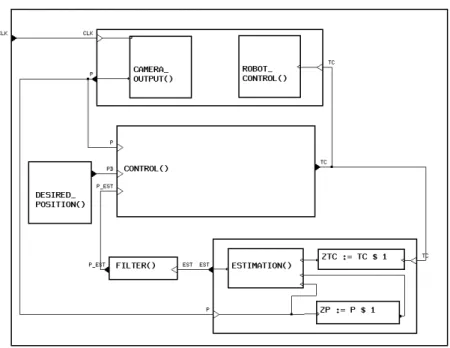
past value ofP and the camera velocity can be expressed using the delay opera-tor $. In addition, we smooth the output of this process, by computing the mean value of the current estimation and of the two previous ones. The control process presented previously is reused with the name CONTROL. The estimation process is added to it in such a way that it is executed in parallel with the control law, as shown in Fig. 3. Textually, the program is shown in Fig. 3(b).
We have here another example of the significance of the synchronous hypothe-sis in the framework of such applications. Indeed, in order to improve the behavior of the control law, theC matrix is here computed using each new value provided by the measurement and the estimation processes (P and p est instead of Pd and pd). According to the synchrony hypothesis, the value at instant t of the C matrix is updated using the estimated 3D parameters and the current position of the primitive in the image at the same logical instantt.
3
S
IGNAL
GT ˙ι tasks for the reconstruction strategy
The previous section gave a framework for the specification and implementation in SIGNALof vision-based tasks as well as estimation algorithms. Once a library of such modules is available, the specification of higher-level, more complex behav-iors requires the possibility to combine these tasks in various ways. Especially, one wants to combine them in sequences, starting and interrupting them on the occurrence of events, that can be either external (coming from logical sensors) or internal (e.g., reaching of certain thresholds). This level of robot programming ne-cessitates preemption structures for concurrent tasks. The purpose of SIGNALGT˙ι is precisely to augment SIGNAL with objects and operations for the construction of such preemptive hierarchies of data flow tasks.
The features of SIGNALGT˙ι are presented in Subsection 3.1. In Subsection 3.2, we describe the particular sequencings of vision-based tasks in our application and the use of SIGNALGT˙ι for programming this.
3.1
The preemption of data-flow tasks in S
IGNALGT
˙ι
and their sequencing [24]. The motivation is to provide ways of representing behaviors switching between different modes of continuous interaction with their environment. These modes are identified by time intervals delimited by discrete start and end events, and within which tasks are executed. The application domain is the control of physical processes e.g. signal processing or robotics, featuring both computations on flows of sensor data, and discrete transitions in a control automaton.
For example in a speech recognition system [17], the processing of the acous-tic signal features a segmentation treatment: boundaries of the segments are deter-mined by changes in the signal. These are detected by comparison with an average value, which is computed on a time window on its past values. Such an applica-tion presents succesive modes or phases: a phase of initializaapplica-tion must compute the value of this average, and then the regular computation can be performed. Hence two phases (reinitialization and computation) alternate on complementary, periodic time intervals. The sequencing between these phases is intrinsic: it is im-posed by dependencies on results produced and consumed. Our goal is to provide a programmer with language constructs enabling the explicit designation of the phases in a process. This is achieved by subdividing its activity interval into sub-intervals for the different modes, and associating sub-activities to each of them.
In SIGNALGT˙ι, data flow and sequencing aspects are both encompassed in
the same language framework, thus relying on the same model for their execution and analysis (for the compilation and verification of correctness of programs). In this approach, a data flow application is considered to be executed from an initial state of its memory at an initial instantα; it is before the first event of the reactive execution. A data flow process has no termination specified in itself: therefore its end at instantω can only be decided in reaction to external events or the reaching of given values. Henceω is part of the execution, and the time interval on which the application executes is the left-open, right-closed interval ]α,ω].
Time intervals. They are introduced in order to enable the structured decom-position of the interval ]α,ω] into sub-intervals as illustrated in Figure 4, and their association with processes [24]. Such a sub-interval I is delimited by oc-currences of bounding events at the beginning B and at the end E. It has the value inside between the next occurrence of B and the next occurrence of E, and outside otherwise. It has an initial value I0 (inside or outside). This is written: I := ]B, E] init I0. Like ]α,ω], sub-intervals are left-open and right-closed. This choice is coherent with the behavior expected from reactive
automata: a transition is made according to a received event occurrence and a cur-rent state, which results in a new state. Hence, the instant where the event occurs belongs to the time interval of the current state, not to that of the new state. The operator compl I defines the complement of an interval I, which is inside when I is outside and reciprocally. Operators open I and close I respec-tively give the opening and closing occurrences of the bounding events. Occur-rences of a signal X inside interval I can be selected by X in I, and reciprocally outside by X out I. In this framework, open I is B out I, and close I is E in I.
Tasks. They consist in associating some (sub)process of the application with some (sub)interval of ]α,ω] on which it is executed. Traditional processes in SIGNAL are tasks active on ]α,ω]: they are persistent throughout the whole
application. Inside the task interval, the task process is active i.e., present and executing normally. Outside the interval, the process is inexistent i.e., absent and the values it keeps in its internal state are unavailable. In some sense, it is out of time, its clock being cut.
Tasks are defined by the process P to be executed, the execution interval I, and the starting state (current, or initial) when (re-)entering the interval. More precisely, the latter means that, when re-entering the task interval, the process can be re-started from its current state at the instant where the task was suspended (i.e., in a temporary fashion): this is written P on I. Figure 5(a) illustrates that the possible behaviors of task P on I are those that process P would have had on interval ]α,ω], but they are split in time on the successive occurrences of interval I.
Alternately, a task can be re-started from its initial state as defined by the declaration of all its state variables, if the task was interrupted (meaning: aborted in a definitive fashion): P each I. In this case, as illustrated in Figure 5(b), the behaviors of task P each I are like prefixes of those that P would have had on ]α,ω], on each of the successive occurrences of interval I. In that sense, each of these successive occurrences of I is a new ]α′,
ω′
], ]α′′,
ω′
], ..., for P.
The processes associated with intervals can themselves be decomposed into sub-tasks: this way, the specification of hierarchies of complex behaviors is pos-sible.
Task sequencing and preempting. It is achieved as a result of constraining intervals and their bounding events, and associating activities to them by
con-structing hierarchical tasks. Parallelism between several tasks is obtained natu-rally when tasks share the same interval, or overlapping intervals. Sequencing tasksthen amounts to constraining the intervals of the tasks, by constraining their bounding events. Using on and each, as defined above, enables control of ac-tivities and more elaborate behaviors can be specified. This way, it is possible to specify hierarchical parallel place/transition systems. Each time interval holds some state information, and events cause transitions between these states.
For example, in the behavior illustrated in Figure 6(a), a transition leads from the initial place S1 to place S2 on the occurrence of an event E, except if the event C occurs before, leading in place S3. If E and C happen synchronously or are constrained to be equal, then both places S2 and S3 are entered. This is a sub-behavior attached to a place entered upon event A and left upon event B. This can be coded by a task and intervals such that the closing of the one is the opening of the other, as in the code shown in Figure 6(b). This example illustrates a hierarchy of tasks and intervals; it could also have featured data-flow equations. This is the advantage of embedding such constructs into a data-flow language and environment: it enables the integration of the two aspects for the specification of hybrid applications.
The encoding of time intervals and tasks into the SIGNALkernel [24] is
imple-mented as a pre-processor to the SIGNALcompiler, called SIGNALGT˙ι. It has also been used in the specification and implementation of a model of the controller of a power transformer station and behavioral animation in a computer graphics-based simulation environment.
3.2
Reconstruction Strategies for Complex Scenes
Sequencing vision tasks. From the point of view of the vision application, we are interested in the reconstruction of environments composed of several objects such as cylinders and polyhedral objects. In order to obtain a precise and robust es-timation of the structure of a selected primitive, the camera fixates at and gazes on it and performs a particular motion using active vision. So, the estimation has to be successively performed for each primitive of the scene, with different phases: selection of a primitive, precise active estimation, and concurrently, coarse es-timation of the other ones, as well as the creation or the update of a list of 2-D segments which contains a 2-D description of the observed scene. For this, we de-fine tasks which associate the structure estimation and other processes with a time intervalon which they are active (see Figure 7). The transitions between tasks are discrete events and are function of the image data, the estimated parameters of the
primitives, and the state of the list of segments. Concerning termination of esti-mation processes, each active estiesti-mation ends when all the primitive parameters have been accurately computed with a sufficient precision. Each coarse estimation ends when the corresponding segment gets out of the image or when the active es-timation ends. After each eses-timation, the 2-D list of segment is updated, as well as the 3D map of the scene, a new segment is chosen and an other estimation is performed.
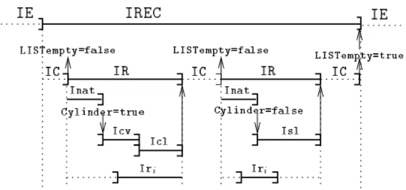
Figure 7 illustrates the specification of the behavior of the system using a pos-sible execution trace. An exploration phase computes a new camera position and detects in the corresponding image the list of 2-D segments; it is active during the time interval IE. In alternance with this, i.e.when not in IE, the scene recon-struction process is active on IREC. It is itself an alternance between a primi-tive selection process, on interval IC, and the primitive reconstruction. The se-lection chooses a segment in the list to be considered. If the list is empty (i.e., LISTempty=true), it causes the scene reconstruction (IREC) to exit. When the list is not empty, the primitive reconstruction process for the chosen primi-tive on IR is itself decomposed into sub-activities. It begins with a recognition process which estimates the nature of the considered primitive (segment or cylin-der), on Inat, which ends with the boolean event Cylinder. It continues with the estimation of the parameters of its 3D structure (according to the value of Cylinder: in the case of a segment (Cylinder=false), only its length on interval Isl; in the case of a cylinder (Cylinder=true), its radius and posi-tion of axis on Icv, and then its length on Icl). In parallel with this estimaposi-tion, a coarse estimation of some primitives can be performed on intervals Iri. After
each estimation of a primitive, the list of 2D segments is updated and a new se-lection is performed on IC. Each vision-based task incorporated in this scheme is a data-flow task based on the visual servoing approach. They are implemented as described in Section 2.
Termination and parallelism. Interesting points of the specification in SIG -NALGT˙ι are the treatment of the termination and sequencing of vision data-flow tasks, and that of the parallelism between them.
A data-flow process defines, like our vision tasks, a behavior, but not a termi-nation : this aspect must be defined separately. One way of deciding on termina-tion of a task is to apply criteria for reaching a goal depending on a conditermina-tion in-volving acquired sensor values or computations (e.g. a given precision is reached). The evaluation of this condition must be performed at all instants: hence this
eval-uation is another data flow treatment. The instant when the condition is satisfied can be marked by a discrete event, which, causing termination of the task, can also cause a transition to another task at the higher level of the reactive sequencing. In this sense, this event can be used to specify the end of the execution interval of the task. Evaluation of such conditions can be made following a dynamic evolution: a sequence of modes for evaluation of the condition can be defined, becoming finer (and possibly more complex) when nearing interesting or important values.
Parallelism between two tasks is transparent to the programmer using the com-position operator. This is the case, for example, of the coarse estimation process and the active estimation process. To perform these estimations, they both use the same information (e.g. the measure of camera velocity, the image data at current and previous instants), in such a way, according to the synchronous hypothesis, that they can use it at the same logical instant. In fact, we have here a parallelism of specification, and the compiler manages all the synchronization and communi-cation between tasks.
Part of the specification in SIGNALGT˙ι corresponding to Fig. 7 is given in
Fig. 8, in a simplified form keeping only the essential aspects, for the sake of brevity and readability (ie skipping declarations and some of the structure of the actual program). It does not detail the processes associated to the intervals, which can be described as follows:
• Exploration, which builds a 2-D list of segments, and outputs the boolean signal LISTempty at the value false, hence ending interval IE.
• Choice outputs the boolean signal LISTempty: the occurrence of this signal ends interval IC.
• Nature outputs the boolean signal Cylinder, which ends interval Inat. The value of Cylinder is true if the primitive is a cylinder, false if it is a segment.
• Cylinder vertex, Cylinder length and Segment length out-put the respective precision measurespreci which, when they reach a
de-sired valueεi, end the respective intervals.
4
Implementation in a Robot Cell
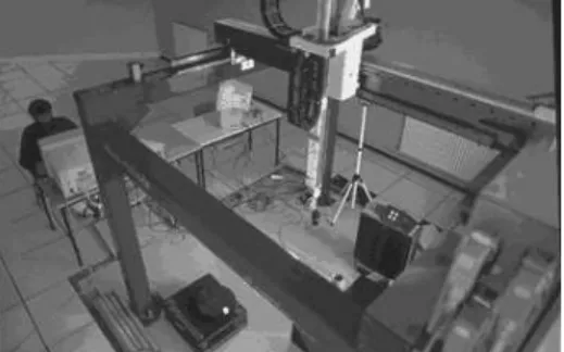
The whole application presented in this paper has been implemented with SIG -NALon an experimental testbed composed of a CCD camera mounted on the end
effector of a six degrees of freedom cartesian robot (see Fig. 9(a)). The image processing part is implemented in C and performed on a commercial image pro-cessing board (EDIXIA IA 1000). The implementation of the control law, the 3D structure estimation and the sequencing was carried out using the SIGNAL
lan-guage running on a SPARC 20 workstation. Fig. 9(b) shows our testbed robot architecture.
Figure 10 shows a graphical view of the reconstruction environment, which was built using OSF/Motif. The event-based management of this graphical inter-face is also programmed in SIGNAL; only X11 functions are defined and called as external processes. In Fig. 10, looking from the bottom to the top of the environ-ment, the following are represented: the current state of the different time inter-vals (i.e., activity of tasks), the evolution of the parameters describing the selected primitive, the error between the current and the desired position of the primitive in the image, an automaton-like representation of the behavior, the image with the list of segments superimposed on it and finally the current representation of the reconstructed scene.
5
Related work and discussion
5.1
Related work
A review of the techniques classically used for real-time programming is given in [5]. The application of real-time techniques to vision applications is reviewed in [27] The most common model of time for concurrent programming is asyn-chrony (see e.g., [2, 15, 22]). Two main approaches raised: one is based on for-mal methods (such as finite state automata or Petri Net), the other is based on tools able to express concurrency (real time OS, or concurent programming lan-guages). Let us examine first the transition systems based approach. The finite state automata are well known tools, deterministic, efficient and they allow the formal verification of properties. However, the composition of little automata can yeld to a very big one often impossible to understand; furthermore a little change in the specification can provoke a deep transformation of the automaton. Finally, let us point out that the expression of parallelism and preemption of tasks are not supported by this formalism. Petri Nets are often used for small applications and if they support concurrency, they do not support hierachical design, and they are not deterministic.
Programming Languages such as OCCAM(CSP) or ADAhave numerous
advan-tadges. They are well structured and allow a good modularity. But they are asyn-chronous and thus non-deterministic. The synchronisation between processes is performed during the execution and is unpredictable. Thus they can hardly be used for reactive system implementation. The most classical way for real time sys-tems integration is the connection of classical programs using real-time Operating System (OS) primitives. Here, the main problem is the number of programs to analyse and connect: diagnostic and maintenance is difficult, temporal constraints are not expressed in the tasks (programs) description but are satisfied using the OS primitives for process synchronization/communication. This leads to systems which are generally non deterministic, and on which no safety properties can be formally guaranteed.
On the other side, we find the family of synchronous languages. The main drawbacks of a classical asynchronous implementation of reactive systems can be avoided using this class of languages. Resulting from the synchrony hypothesis, these languages are determistic, they allow concurrency and hierarchical spec-ification. They provide safety, logical correctness (respect of the input/output specification), and temporal correctness. Furthermore they are based on a mathe-matically well defined semantics, supporting verification tools. For example, the compilation of SIGNALcode provides a graph on which static correctness proofs can be derived. It can also produce an equivalent dynamical equations system, on which dynamical properties can be proved. Using the tool SIGALI, the absence
of deadlocks or properties specific to the application can be checked. In [18], a variety of formal specifications and implementations of a real-time reactive sys-tem are proposed. This book proposes a comparative survey of various languages (among which SIGNAL[1], and also LUSTRE, ESTEREL, STATECHARTS, ADA, ...) used to specify, verify and implement a controller for a robotic production cell.
An approach related to our integration of data-flow and sequencing is AR
-GOLUS [16]. It integrates ARGOS(hierarchical parallel automata) with LUSTRE
(data flow); in our case, we try to specify sequencing in a more declarative style. A general study of preemption and concurrency, lead in combination with the im-perative synchronous language ESTEREL, resulted in the possibility to control the starting, suspension, resuming and termination of external tasks [6]. However, the fact that these tasks can not be defined within the same language framework limits the control on interactions between different levels.
From the point of view of robot programming, the approach of applying syn-chronous languages is adopted in the ORCCAD environment [25]. This approach
aims at a complete design environment for robot programming, and has more gen-eral goals than ours, which is focused on robot vision and the application of the SIGNALenvironment as it is. However, task-level programming is done using ES
-TEREL [9], and the data-flow specification of control laws is done using another
formalism at a different level, and controlled as an external task as said before.
5.2
Discussion
First of all, we must recognize that a data-flow language such as SIGNAL is not adapted to all kinds of computation. For example, image processing or linear alge-bra cannot generally be performed with SIGNAL(or only with difficulty). Arrays are available in SIGNAL, but the algorithms involved for this kind of computation (for example the inverse of a matrix) are not naturally data-flow. Thus we use ex-ternal functions written with other languages (C and Fortran for instance), which are called from the SIGNALprogram. The same method is used in our application for the management of the set of segments which is obviously not the application domain of synchronous languages. However, the use of such functions is not per-formed asynchronously: they are considered as any function defined in SIGNAL, thus we do not leave the synchronous framework. Furthermore, the management of asynchronous inputs or interruptions is not supported. However, this is not necessary in this kind of application where the inputs are provided regularly and periodically (here at video rate). Finally, dynamical management of time at the execution is not treated here, but this is not necessary due to the regular aspect of the loops.
Let us now emphasize the merits of synchronous languages, and more partic-ularly SIGNAL, for this kind of applications. Dealing with implementation issues, advantages can be found at both control and task level. The data flow framework is particularly appropriate for the specification of visual servoing because of the equational and data flow nature of the closed-loop control laws, which can be implemented as control functions between sensor data and control outputs. The possibility of implicitly specifying parallel behaviors has been proved useful for the 3D structure estimation using active vision. The synchrony hypothesis corre-sponds well to the model of time in the equations defining the control laws. The second point concerns tasks sequencing and preempting. The language-level in-tegration of the data flow and sequencing frameworks have been achieved as an extension of SIGNAL: SIGNALGT˙ι. It enables the definition of time intervals, their association with data flow processes and provides constructs for the spec-ification of hierarchical preemptive tasks. This way, it offers a multi-paradigm
language combining the data flow and multi-tasking paradigms, for hybrid ap-plications blending (sampled) continuous and discrete transition aspects. Using SIGNALGT˙ι, we can design a hierarchy of parallel automata, thus we have the advantages of both the automata (determinism, tasks sequencing) and concur-rent programming languages (parallelism between tasks) without their drawbacks. Note that SIGNALGT˙ι has not been developed only for the application presented in this paper, but for the specification of other complex applications (such as be-havioral animation in computer graphics [10] or the design of a transformer power station [21]).
The semantics of SIGNALis also defined via a mathematical model of multiple
clocked flows of data and events. SIGNALprograms describe relations on such ob-jects: in that sense, programming is done via constraints. The compiler calculates the solutions of the system and may thus be used as a proof system. Its program-ming environment, which is not limited to the compiler, features tools for the automated analysis of formal properties. The compilation of SIGNAL code pro-vides a dependencies graph on which static correctness proofs can be derived: it checks automatically the network of dependencies between data flows and detects causal cycles, temporal inconsistencies from the point of view of time indexes. SIGNALsynthesizes automatically the scheduling of the operations involved
in-side a control-loop (note that this work is an error-prone task when done by hand in classical C-like languages), and this scheduling is proved to be correct from the point of view of data dependencies. Furthermore, the SIGNAL-code is thus easy
to modify since the re-synthesis is automatic. Finally, the compiler synthesizes automaticallya global optimization of the dependencies graph.
The SIGNAL environment provides other tools (note that they have not been
used directly in our application; see [1]): SIGNALcan produce an equivalent dy-namical equation system, on which dydy-namical properties can be proved. The absence of deadlocks (liveness), reachability of states (or on the contrary non-reachability of a “bad” state), or properties specific to the application can thus be checked. These properties (both static and dynamic) checking tools are important at two levels: for development purposes it is important to verify that the system re-ally has the expected or required behavior; and for the certification of the safety of the systems, which is meaningful regarding safety-critical application. Research is going on concerning the distribution of SIGNALprograms on parallel machines,
with automatic generation of separate code modules and of their communications. Finally, the compilation of SIGNAL into VHDL opens the ways towards hard-ware/software co-design. We claim that these tools are important in the context of software engineering, and that other classical asynchronous languages do not
pro-vide them (other synchronous languages like ESTEREL or LUSTRE provide this
kind of tools).
As a conclusion, the contribution of the synchronous approach, and of SIGNAL
in particular, is that it has a programming style closer to a control engineer’s speci-fication and that it provides him with a set of tools releaving him from error-prone tasks. Even if some other languages are sometimes provided with interesting other functionalities (management of the duration of tasks, dynamic scheduling, . . . ), they do not offer the ones mentioned here, based on the synchronous model.
6
Conclusion
The objective of this paper is to report on an experiment showing that synchronous languages are suitable for specifying and implementing vision tasks at different levels: camera motion control (vision-based closed loop control), perception task (structure estimation from controlled motion), and application (vision task se-quencing). The first question addressed is to examine what the advantages are of using a data-flow synchronous language for visual servoing programming. The data flow paradigm is particularly adequate and suitable because of the equational and data flow nature of the closed loop control laws, which can be implemented as control functions between sensor data and control output. The possibility of specifying implicitely parallel behaviors proved useful when adding structure es-timation. The synchrony hypothesis corresponds well to the model of time in the equations defining the control laws, and it is used by the compiler to perform a static verification of the logical timing correctness.
The second point concerns the specification of more complex applications, involving transitions between modes, i.e. the sequencing of data-flow tasks. The language-level integration of the data flow and task preemption paradigms is made in an extension to SIGNAL: SIGNALGT˙ι. It enables the designation of time inter-vals, their association with data flow processes in order to form tasks, and the sequencing of these data flow tasks. This way, the whole application can be spec-ified in SIGNAL, from the discrete event driven transition behavior down to the (sampled) continuous servoing loop. The synchrony hypothesis corresponds well to the model of time in the equations defining the control laws, and it is used by the compiler to perform a static verification of the logical timing correctness. Implementation and experiments have been carried out on a robotic cell.
As a perspective in the direction of robot programming, it would be interesting to consider a generalization of the structure of data-flow tasks proposed in this
pa-per, towards a programming environment dedicated to the design of sensor-based control tasks following the task-function approach, as presented in the perspec-tives of [25].
Acknowledgment. This work was partly supported by the CNRS inter-PRC project VIA (Vision Intentionnelle et Action) and by the MESR under contribu-tion to a student grant. The authors wish to thank Samuel Ketels and Florent Martinez who implemented part of the experimental work.
References
[1] T. Amagbegnon, P. Le Guernic, H. Marchand, and E. Rutten. Signal – the specification of a generic, verified production cell controller. In C. Lewerentz and T. Lindner, editors, Formal Development of Reactive Systems - Case Study Production Cell. Lecture Notes in Computer Science, 891, Springer-Verlag, 1995.
[2] T.P. Baker and O. Pazy. Real time features forADA 9x. In IEEE Real-Time Systems Symposium, pages 172–180, December 1991.
[3] A. Benveniste. Synchronous languages provide safety in reactive systems design. Control Engineering, pages 87–89, September 1994.
[4] A. Benveniste and G. Berry. Real-time systems designs and programming. Proc. of the IEEE, 79(9):1270–1282, September 1991.
[5] G. Berry. Real time programming: Special purpose languages or general purpose languages. In 11th IFIP World Congress, pages 11–17, San Fran-cisco, California, August 1989.
[6] G. Berry. Preemption in concurrent systems. In 13th Conf. on Founda-tions of Software Technology and Theoretical Computer Science. LNCS 761, Springer Verlag, Bombay, India, December 1993.
[7] F. Boussinot and R. De Simone. TheESTERELlanguage. Proc. of the IEEE, 79(9):1293–1304, September 1991.
[8] F. Chaumette, S. Boukir, P. Bouthemy, and D. Juvin. optimal estimation of 3D structures using visual servoing. In Proc. of IEEE Conf. on Computer Vision and Pattern Recognition, pages 347–354, Seattle, USA, June 1994.
[9] E. Coste-Manire, B. Espiau, and E. Rutten. A task-level robot programming language and its reactive execution. In IEEE Int. Conf. on Robotics and Automation, volume 3, pages 2751–2756, Nice, France, May 1992.
[10] S. Donikian and E. Rutten. Reactivity, concurrency, data-flow and hierarchi-cal preemption for behavioral animation. In Eurographics Workshop on Pro-gramming Paradigms in Graphics, Maastricht, The Netherlands, September 1995.
[11] B. Espiau, F. Chaumette, and P. Rives. A new approach to visual servoing in robotics. IEEE Trans. on Robotics and Automation, 8(3):313–326, June 1992.
[12] N. Halbwachs. Synchronous programming of reactive systems. Kluwer, 1993.
[13] D. Harel. STATECHARTS: a visual formalism for complex systems. Science
of Computer Programming, 8(3):231–274, June 1987.
[14] D. Harel and A. Pnueli. On the development of reactive systems. In K.R. Apt, editor, Logics and Models of Concurrent Systems, volume 13 of NATO ASI Series, Springer Verlag, pages 477–498, New York, 1985.
[15] C.A.R. Hoare. Communicating Sequential Process. Prentise-Hall Int., 1985. [16] M. Jourdan, F. Lagnier, F. Maraninchi, and F. Raymond. A multiparadigm language for reactive systems. In Proc. of the IEEE Int. Conf. on Computer Languages, Toulouse, France, May 1994.
[17] P. Le Guernic, M. Le Borgne, T. Gautier, and C. Le Maire. Programming real time application with SIGNAL. Proc. of the IEEE, 79(9):1321–1336, September 1991.
[18] C. Lewerentz and T. Lindner. Formal Development of reactive systems, vol-ume 891 of Lecture Notes in Computer Science. Springer Verlag, 1995. [19] E. Marchand and F. Chaumette. Controlled camera motions for scene
re-construction and exploration. In IEEE Int. Conf. on Computer Vision and Pattern Recognition, CVPR’96, pages 169–176, San Francisco, California, June 1996.
[20] E. Marchand, E. Rutten, and F. Chaumette. From data-flow task to multi-tasking: Applying the synchronous approach to active vision in robotics. IEEE Trans. on Control Systems Technology, 5(2):200–216, March 1997. [21] H. Marchand, E. Rutten, and M. Samaan. Synchronous design of a
trans-former station controller inSIGNAL. In Proc of 4th IEEE Conf. on Control Applications, Albany, New York, USA, September 1995.
[22] R. Milner. A Calculus of Communicating Systems. Number 92 in Lecture Notes in Computer Science. Springer Verlag, 1980.
[23] P.J. Ramadge and W.M. Wonham. The control of discrete events systems. Proc. of the IEEE, 77(1):81–97, January 1989.
[24] E. Rutten and P. Le Guernic. Sequencing of data flow tasks in SIGNAL. In ACM SIGPLAN Workshop on Language, Compiler and Tool Support for Real-Time Systems, Orlando, Florida, June 1994.
[25] D. Simon, B. Espiau, E. Castillo, and K. Kapellos. Computer-aided design of a generic robot controller handling reactivity and real-time controller issues. IEEE Trans. on Control Systems Technology, 1(4):213–229, December 1993. [26] Y. Sorel. Massively parallel computing systems with real-time constraints: the algorithm-architecture adequation methodology. In Massively Parallel Computing systems Conference, 1994.
[27] A.D.H. Thomas, M.G. Rodd, J.D. Holt, and C.J. Neill. Real time industrial visual inspection: A review. Real Time Imaging, 1(2):139–158, June 1995.
List of Figures
1 The SIGNALdesign environment. . . 7
2 Modular description of a general visual servoing process. . . 11
3 Control and estimation in parallel. . . 28
4 Time intervals sub-dividing ]α,ω]. . . 29
5 Tasks associating a time interval with a process. . . 29
6 Task sequencing and preempting in SIGNALGT˙ι. . . 30
7 Specification of the sequencing in terms of activity intervals: a possible trace. . . 30
8 Specification of the reconstruction strategy. . . 31
9 The experimental robotic cell. . . 32
Contents
1 An experiment with SIGNALin robot vision 2
The synchronous methodology. . . 2
Synchronous languages. . . 2
Application to active robot vision. . . 3
2 SIGNALequational programming of robotics tasks 4 2.1 The SIGNALequational data-flow real-time language . . . 5
2.2 The Control and Estimation Algorithms . . . 8
General issues. . . 8
Visual Servoing Control. . . 9
Estimation of Structure From Controlled Motion. . . 10
3 SIGNALGT˙ι tasks for the reconstruction strategy 12 3.1 The preemption of data-flow tasks in SIGNALGT˙ι . . . 13
Time intervals. . . 13
Tasks. . . 14
Task sequencing and preempting. . . 15
3.2 Reconstruction Strategies for Complex Scenes . . . 15
Sequencing vision tasks. . . 15
Termination and parallelism. . . 16
4 Implementation in a Robot Cell 18 5 Related work and discussion 18 5.1 Related work . . . 18
5.2 Discussion . . . 20
(a) SIGNALgraphical specification. (|(| P := CAMERA OUTPUT{CLK} | ROBOT CONTROL{Tc} |) | Tc := CONTROL{P,Pd,p est} | Pd := DESIRED POSITION{} | p est := FILTER{est} |(| ZTc := Tc$1 | ZP := P$1 | est := ESTIMATION{P,ZP,ZTc} |) |)
(b) Equational specification in SIGNAL.
Figure 4: Time intervals sub-dividing ]α,ω].
(a) Task on interval I. (b) Task each interval I.
(a) Hierarchical place/transition system. (| S1 := ](D in S2 default F in S3), E default C] init inside | S2 := ]E in S1, D] init outside | S3 := ]C in S1, F] init outside |) each ]A, B]
(b) Specification in SIGNALGT ˙ι.
Figure 6: Task sequencing and preempting in SIGNALGT˙ι.
Figure 7: Specification of the sequencing in terms of activity intervals: a possible trace.
Application:
(| IE := ] when LISTempty, when not LISTempty] init inside | IREC := comp IE
| Exploration each IE
| Structure estimation each IREC |)
Structure estimation:
(| IC := ] close Icl default close Isl, LISTempty] init inside | IR := comp IC
| Choice each IC
| Primitive estimation each IR |)
Primitive estimation: (| Optimal estimation
| (| Coarse estimation1 | . . . | Coarse estimationn |)
|)
Coarse estimationi:
(| Iri := ] New Segment, Segment Lost ] init outside
| Coarse estimation each Iri
|)
Optimal estimation:
(| Inat := ] close Isl default close Icl, Cylinder] init inside | Nature each Inat
| Icv := ] when Cylinder, when (|preccv|< εcv)] init outside
| Cylinder vertex each Icv
| Icl := ] close Icv, when (|preccl|< εcl)] init outside
| Cylinder length each Icl
| Isl := ] when not Cylinder, when (|precsl|< εsl)] init outside
| Segment length each Isl |)
Figure 8: Specification of the reconstruction
(a) Camera mounted on a 6 dof robot. VME Bit3 sbus SIGNAL Bit3 Bit 3 EDIXIA IA 1000 Robot Control Camera CCD 6dof ROBOT AFMA Sun Sparc 20 (b) Architecture.
screen dump


![Figure 4: Time intervals sub-dividing ]α,ω].](https://thumb-eu.123doks.com/thumbv2/123doknet/12258169.320598/30.918.200.680.290.550/figure-time-intervals-sub-dividing-α-ω.webp)