HAL Id: hal-01247644
https://hal.archives-ouvertes.fr/hal-01247644
Submitted on 4 Jan 2016
HAL is a multi-disciplinary open access
archive for the deposit and dissemination of
sci-entific research documents, whether they are
pub-lished or not. The documents may come from
teaching and research institutions in France or
abroad, or from public or private research centers.
L’archive ouverte pluridisciplinaire HAL, est
destinée au dépôt et à la diffusion de documents
scientifiques de niveau recherche, publiés ou non,
émanant des établissements d’enseignement et de
recherche français ou étrangers, des laboratoires
publics ou privés.
A smart multifunction diffractive lens experimental
validation for future PV cell applications
Albarazanchi Abbas, Philippe Gerard, Pierre Ambs, Patrick Meyrueis, Giang
Nam Nguyen, Kevin Heggarty
To cite this version:
Albarazanchi Abbas, Philippe Gerard, Pierre Ambs, Patrick Meyrueis, Giang Nam Nguyen, et al.. A
smart multifunction diffractive lens experimental validation for future PV cell applications. Optics
Express, Optical Society of America - OSA Publishing, 2016, 24 (2), �10.1364/OE.24.00A139�.
�hal-01247644�
A smart multifunction diffractive lens
experimental validation for future PV cell
applications
Abbas Albarazanchi,1* Philippe Gerard,1,2 Pierre Ambs,3 Patrick Meyrueis,1 Giang-Nam Nguyen,4 and Kevin Heggarty4
1Uninversite de Strasbourg, Icube laboratoire,IPP,Pole API, 300 Boulevard S. Brant, F-67412 Illkirch Cedex,France 2 INSA Strasbourg, 24 Boulevard de la victoire, 67000 Strasbourg, France
3University de Haute Alsace, Laboratoire MIPS,ENSISA, 12 rue des Freres Lumiere, F-68093 Mulhouse Cedex,
France
4Télécom Bretagne, Département Optique, Technopôle Brest-Iroise, 29238 Brest Cedex 3, France
*abbas.al-barazanchi@etu.unistra.fr
Abstract: Recently, diffractive optical elements (DOE’s) have attracted
more attention for applications to third generation PV cells. Some DOE types can provide multiple functions such as spectrum splitting and beam concentration (SSBC) simultaneously. An off-axis diffractive lens has been designed and experimentally proved its ability to achieve the SSBC. This lens can be used to separate the solar spectrum in the Vis-NIR range into two bands with a low concentration factor, and about 70 % optical efficiency. It is expected that this kind of lens can be integrated with the lateral multijunction PV cells to build an effective compact solar system. 2015 Optical Society of America
OCIS codes: (050.1970) Diffractive lenses; (080.0080) Geometric optics; (220.0220) Optical
design and Fabrication; (350.6050) Solar energy.
References and links
1. W. Shockley, and H. J. Queisser, “Detailed balance limit of efficiency of p‐n junction solar cells,” J. Appl. Phys (32) 510 (1961).
2. J. F. Geisz, D. J. Friedman, J. S. Ward, A. Duda, W. J. Olavarria, T. E. Moriarty, J. T. Kiehl, M. J. Romero, A. G. Norman and K. M. Jones, “40.8% efficient inverted triple-junction solar cell with two independently metamorphic junctions,” Appl. Phys. Lett. 93(12), (2008).
3. R. R. King., A. Boca., W. Hong, X.-Q. Liu, D. Bhusari, D. Larrabee, K. M. Edmondson, D. C. Law, C. M. Fetzer, S. Mesropian, and N. H. Karam, “Band-gap-engineered architectures for high-efficiency multijunction concentrator solar cells”, in proceeding of the 24th European photovoltaic Solar cells conference, Hamburg, Germany(2009).
4. M. A. Green, “Third generation photovoltaics: ultra-high conversion efficiency at low cost,” Progress in Photovoltaics 9(2), 123-135 (2001).
5. C. Yang, P. Edwards, K. Shi, and Z. Liu., “Proposal and demonstration of a spectrometer using a diffractive optical element with dual dispersion and focusing functionality,” Opt. Letters 36(11), 2023-5 (2011).
6. Y. Jia-Sheng, W. Jin-Ze, H. Qing-Li, D. Bi-Zhen, Z. Yan, and Y. Guo-Zhen “A single diffractive optical element implementing spectrum-splitting and beam-concentration functions simultaneously with high diffraction efficiency,” Chin. Phys. b 22(3), 34201 (2013).
7. Q. Huang, J. Wang, B. Quan, Q. Zhang, D. Zhang, D. Li, Q. Meng, L. Pan, Y. Wang, and G. Yang, “Design and fabrication of a diffractive optical element as a spectrum-splitting solar concentrator for lateral multijunction solar cells,” Appl. Optics 52(11), 2312-2319 (2013).
8. C. Michel, J. Loicq, F. Languy, S. Habraken, “Optical study of a solar concentrator for space applications based on a diffractive/refractive optical combination,” Sol. Energy Mater. Sol. Cells 120(part A), 183–190 (2014). 9. M. Stefancich, A. Zayan, M. Chiesa, S. Rampino, D. Roncati, L. Kimerling, and J. Michel, “Single element
spectral splitting solar concentrator for multiple cells CPV system,” Opt. Express 20(8), 9004-9018, (2012). 10. G. Kim, J. A. Dominguez-Caballero, H. Lee, D. J. Friedman, and R. Menon, “Increased photovoltaic power
output via diffractive spectrum separation,” Phys. Rev. Lett. 110(12), 123901 (2013).
11. P. Wang, J. A. Dominguez-Caballero, D. J. Friedman, and R. Menon, “A new class of multi-bandgap high-efficiency photovoltaics enabled by broadband diffractive optics,” in Progress in Photovoltaics: Research and Applications, (2014).
12. Y. Yao, H. Liu, and W. Wu, “Spectrum splitting using multi-layer dielectric meta-surfaces for efficient solar energy harvesting,” Appl. Phys. A-Mater. 115(3), 713-719 (2014).
13. G. Zubi, J. L. Bernal-Agustin, and G. V. Fracastoro, “High concentration photovoltaic systems applying III-V cells,” Renew. Sust. Energ. Rev. 13(9), 2645-2652 (2009).
14. R. M. Swanson, Handbook of Photovoltaic Science and Engineering (John Wiley & Sons, Ltd , 2005), pp. 449-503, chap. 11 Photovoltaic Concentrators.
15. A. Albarazanchi, P. Gerard, P. Ambs, P. Meyrueis, “Alternative model of a subwavelength diffractive lens proposed for PV cells applications,” IEEE Photon. Technol. Lett. 27(12), 1317-1320 (2015).
16. F. Languy, K. Fleury, C. Lenaerts, J. Loicq, D. Regaert, T. Thibert, S. Habraken, “Flat fresnel doublets made of PMMA and PC: combining low cost production and very high concentration ratio for CPV,” Opt. Express
19(10), A280-A294 (2011).
17. D. Faklis, and G. M. Morris, “Spectral properties of multiorder diffractive lenses,” Appl. Optics 34(14), 2462-2468 (1995)
18. M. V. Kessels, M. El Bouz, R. Pagan, and K. Heggarty, “Versatile stepper based mask-less microlithography using a liquid crystal display for direct write of binary and multi-level microstructures,” J Micro Nanolithogr MEMS MOEMS 6(3), 033002-12 (2007).
19. T. Hessler, M. Rossi, R. E. Kunz, and M. T. Gale, “Analysis and optimization of fabrication of continuous-relief diffractive optical elements,” Appl. Optics 37(19), 4069-4079 (1998).
1. Introduction
Sunlight is one of the important candidates for the renewable and environmentally friendly energy sources. Photovoltaic (PV) cells are the most famous devices that were used to convert the sunlight energy into electrical power directly. The Shockley-Read-Hall equations clarified the limitations imposed on the efficiency of the single p-n junction PV cell [1]. The solar spectrum stretches from ~350 nm to almost 2000nm. Unfortunately, the single junction PV cell is unable to convert all incident photons of the solar spectrum into charge carriers efficiently. Third generation PV cells were proposed as a solution to implement the maximum conversion efficiency, through the technique of several junctions with different band gaps that are vertically stacked [2]. Unfortunately, the implementation of vertical multijunction PV cells requires a very complex fabrication technique, that provides: the tunnel junction, the current matching and the lattice matching [3]. Lateral multijunction PV cells represent an alternative effective technique with the advantage of fabrication simplicity at low costs, where cell stacking and epitaxial technologies are no longer applied [4]. The optical devices must be used to implement the functionalities of spectrum splitting and beam concentration of the spectrum bands into the PV cells laterally arranged. These functionalities were previously achieved by using a diffraction grating, a prism, a Dichroic, and a lens or a mirror, respectively. Recently, much research was focused on the design of a single optical device that can achieve spectrum splitting and beam concentration (SSBC) simultaneously. This technique offers the possibility to reduce the optical losses produced by the effects of interference, reflection and absorption, due to the use of many optical devices. Several researches [5-8], adopted the idea of merging two optical devices such as a grating and a lens into one device, in order to implement the SSBC. Furthermore, a set of prisms [9], a broadband diffractive-optical element (BDOE) [10-12], and meta-surface[12], were designed to efficiently separate and concentrate sunlight into laterally spaced spectral bands. Refractive Fresnel lenses [13, 14], have been for a long time used commercially as concentrators for the photovoltaic systems.
In particular, an off axis diffractive lens with a subwavelength structure profile [15], has demonstrated theoretically, its ability to perform the SSBC simultaneously. Here we explore a planar off-axis diffractive lens digitally quantized into a multilevel structure profile that can implement the spectrum splitting and beam concentration simultaneously, a function that is out of ordinary lenses functionality. Compared with existing devices, an off axis diffractive lens has three major advantages. First, it can provide both functionalities of spectrum splitting and beam concentration compared to a conventional refractive Fresnel lens utilized as a smart concentrator of the sunlight. Second, the device has planar surfaces which potentially allow a low cost production by replicating from a master pattern. Third, it can be used to build a compact efficient solar system.
2. Principle of the proposed (SSBC) lens
In diffractive lenses optical properties are based on geometrical optics and physical optics. It is known, that the diffractive lenses suffer from a high longitudinal chromatic aberration (LCA). The LCA [16], is defined as the difference between the focal distance for each wavelength
λ
i relative to the designed wavelengthλ
Das given by Eq. (1):
( ) ( )
( )
D D i i f f f LCA λ λ λ λ)= − ( (1)Consequently, a polychromatic light source is concentrated at several focal points for many diffraction orders depending on the design parameters of the diffractive lens. These focal points[16], can be defined by Eq. (2):
f
( ) (
λ
i=
λ
Dλ
i) (
⋅
p
m
) ( )
⋅
f
λ
D (2)Where
p
≥
2
is the harmonic degree related to a total thickness in air of the diffractive lens, which is thicker than so called modulo 2π, and m is the diffraction order. Furthermore, its broadband diffraction efficiency [17] is also strongly influenced by the selection of the design parameters, and is defined by Eq. (3):
η
( )
λ
i =sinc2(
m−p⋅[
(ni−1)λ
D (nD−1)λ
i]
)
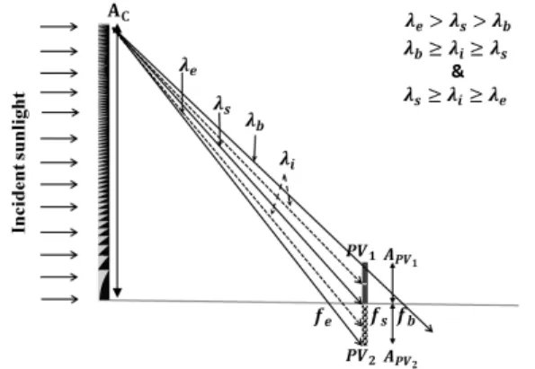
(3) An off-axis diffractive lens was designed in order to achieve the functionalities of the SSBC simultaneously, thanks to the properties aforementioned. The founding idea is simple, and it is based on making the center of the diffractive lens to be on its edge, together with the optimal selection of the design parameters. Thereby, sunlight vertically incident on the front of an off-axis lens, will be concentrated on the optical off-axis, which is perpendicular to its edge, as shown in Fig. 1. The focal points and the diffraction efficiency for the wavelengths of the target spectrum depend on the design parameters of the diffractive lens, as illustrated by Eqs. (2) & (3). Therefore, the lens was designed with the optimal values of λD and p to ensure that the
wavelengths of the sunlight spectrum focus on a short lateral distance range, that means it produces a low LCA. Furthermore, the diffraction efficiency will be retained at the highest value in the first diffraction order by decreasing the distribution of the light power density in multi diffraction orders.
Fig. 1. Schematic diagram that shows the principle of the SSBC of a diffractive lens.
Consequently, we expect that this lens can be used for separating a specific solar spectrum into two bands: band1 which is comprised of the wavelengths between (λb-λs) will be
concentrated at a lateral distance of (fb-fs). Band2 which is comprised of the wavelengths
be placed at a position of fs on either side of the optical axis of the diffractive lens, with each
one being designed with optimized absorption for each separated wavelength band. Thus, these two bands will be absorbed and converted into electrical energy by these two PV cells efficiently. For such optical devices used as concentrators for solar cells, the performance is defined by three factors [17]. First, the geometric concentration factor Cgeo, which is defined
as the ratio between the area of the collector surface AC and the area of the receiver surface APVi (i.e. PV cell). Second, the optical efficiency factor which is defined as the ratio between
the flux absorbed i
PV
φ
by the PV cell and the flux collectedφ
C by the concentrator. Third, the optical concentrator factor Copt which is defined as the product of the two factorsaforementioned, as shown in Eq. (4):
(
)
(
PV C)
PV C opt geo opt C A A i i C = ⋅η = ⋅φ ⋅φ (4)We propose an alternative formula of the optical concentration factor that matches the functionalities of the spectrum splitting and the beam concentration simultaneously. In this formula, the diffraction efficiency is calculated for all the wavelengths in both separated spectrum bands and by taking the average for all the wavelengths. Consequently, the final formula of the optical concentration factor for the implemented functionalities of the SSBC can be defined by Eq. (5):
( )
( )
i k i opt geo opt C k C∑
η λ = ⋅ ⋅ = 1 1 (5)The methodology to calculate the width for each PV cell was introduced in our last publication [15].
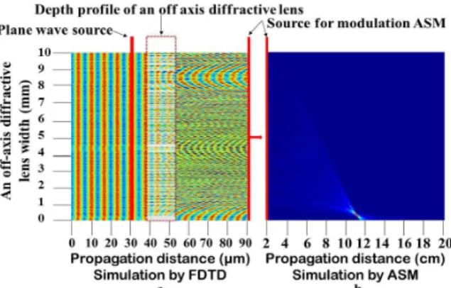
3. A rigorous hybrid propagator (FDTD-ASM)
A hybrid propagator was considered for modelling the lens performance, which is based on the rigorous diffraction theory. This propagator includes a couple of rigorous electromagnetic methods, which are the finite difference time domain method (FDTD) and the Angular Spectrum Method (ASM) [15]. The Free FDTD software "Meep" developed at the “MIT” was used to simulate the propagation of light inside the depth profile of the diffractive optical element (near field). While, the ASM was used to rigorously simulate the light propagation from the front of the diffractive optical elements to the reconstruction plane. The goal of this propagator is to provide an accurate modelling of the electromagnetic field propagation and to correctly predict the coupling effect for all the field components along the boundary of the small features belonging to the lens profile. The principle of the simulation was done through two steps, as shown in Fig. 2.
4. Theoretical validation (Numerical simulation)
An off-axis diffractive lens was designed and its performance tested, by using a hybrid propagator (FDTD-ASM) for TE polarization, in order to validate its ability to implement the SSBC functionality. The design parameters were selected as follows: wavelength 0.6 µm, focal length ~15 cm, pixel size 1 µm, lens diameter 1 cm, and the device material is chosen to be photoresist (refractive index 1.64) for the purpose of the fabrication simplicity and the experimental comparison. These design parameters of an off-axis diffractive lens allow to achieve the splitting of the solar spectrum within the range of the wavelengths Vis-NIR (i.e. 400-1100 nm), into two bands (400-800) nm and (800-1100) nm with a separation distance 11.25 cm. The lens design was quantized to 8-height levels and its optical efficiency was calculated for the desired spectrum band with a 5 nm wavelength variation precision. The designed off-axis diffractive lens appears by the simulation to have the ability to separate the desired spectrum band with the geometric concentration factor 2.32 X and 2.6 X for PV1 and
PV2 cell respectively. This value of Cgeo leads to classify the lens as a concentrator with a
small geometric concentration factor. The lens was optically characterizedby measuring the optical efficiency of the photon flux energy which will be absorbed by the PV cells at a given wavelength and at the separation distance that is d=11.25 cm away from the lens. The averaged optical efficiencies of the lens for the two separated bands are about 70 % and 51 % for PV1 and PV2 cell respectively. Some amount of the photon flux energy of both bands
arrived at the undesired surface of the PV cells, due to the redistribution of the photon flux energy for some wavelengths in several diffraction orders.So, less than 14 % of band1 arrived
at the surface of PV2 cell and less than 12% of band2 arrived at the surface of PV1 cell.
5. Experimental validation (Optical setup measurements)
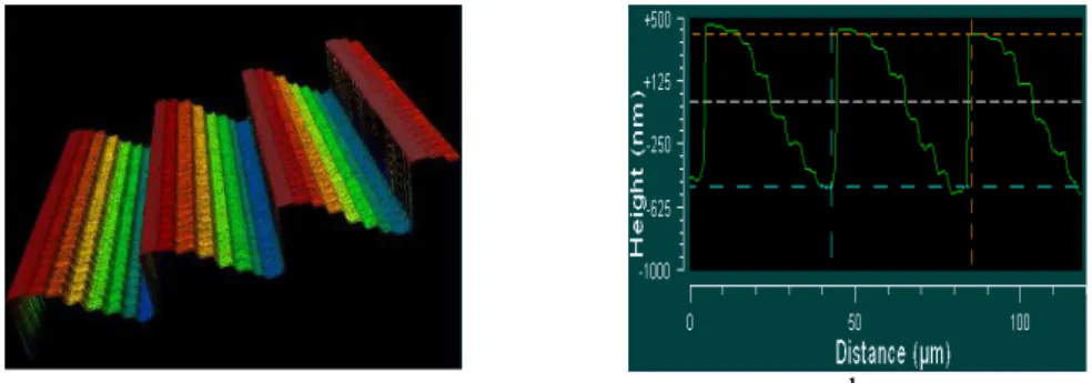
A parallel direct laser writinggrayscale lithography technique [18] was used to fabricate the prototype of a multi-level off-axis diffractive lens, by using a thin film of a positive photoresist (S1800 series). An optical micrograph image is shown in Fig. 3 for a small portion of the fabricated lens, an area of about 1x1 cm2 with the pixel width of 1 µm as well as 8-levels structure profile. The experimental measurements performed by using a Zygo profilometer, as indicated in Fig 3 (a), show the quantization for 8-levels thickness of the fabricated lens with 1µm pixel size and 820 nm is the maximum depth of a high profile step. However, the edges between the phase levels are not perfectly sharp, but rather smoothed
.
Consequently the profile will be close to a continuous-relief instead of a pure binary multilevel-relief [19], due to an effect of “rounding “ in the profile steps which produced from such as the fabrication technique.-a- -b-
Fig. 3.Zygo profilometer measurements for the designed and fabricated an off-axis diffracted lens. (a) 3D interferometric microscope image. (b) Etching profile of the structure in (a).
The optical performance experimental characterization was performed for the fabricated lens by using a particular optical setup, as shown in Fig. 4. This optical setup is operated in the same way that was explained by Peng Wang[11]. The difference in our optical setup is
that we used the Tungsten Halogen from Ocean Optics (type HL-2000) as a white light source which supplies light in the Vis-NIR range of the spectrum. Furthermore, we used the “Ocean Optics Maya pro Spectrometer” to analyze the spectrum of the diffracted light by using the ocean view software. It is important to mention that TE polarisation was used for the simulations and a linear polariser was used in the experiments as a variable attenuator to avoid photodetector saturation. With the relatively large diffractive structures studied here no significant polarisation dependence was encountered either in simulations or experiments.
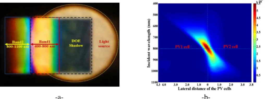
Fig. 4.Schematic diagram of the optical setup used for the optical performance characterization. The spectrum splitting was clearly observed by placing a white plate at the separation distance, as well as from a map of the spatial spectral intensity distribution of the diffracted light power at respective wavelengths, as shown in Fig. 5. Whereas, the false colour scale in Fig. 5(b) represents the relative detected light power per unit area, output by the spectrometer.
Warmer colours indicate higher power. The transmission or optical diffraction
efficiency i
PV
η
was calculated in each separated wavelength band of the fabricated lens according with the theoretical model as given by Eq. (6):
( )
∑
( )
∑
( )
= = = N i o N i PV I i I i i i 1 1λ
η
(6) Where Io and I are the total power for each wavelength over the entire lens area and theoverall area of each separated band, respectively. N and Ni are the integer number of a
translation stage with a movement precision of 100 µm over lens and separated band area, respectively.
-a- -b-
Fig. 5. The images show the SSBC of the lens fabricated. (a) Photograph at the separation distance. (b) Map of the spatial spectral intensity distribution at both of the separation plane (PV cells surface). The measured optical efficiency is compared to the efficiency that obtained from stimulation by using a hybrid propagator (FDTD-ASM) as reported in Fig. 6.
Fig. 6. Comparison of the optical efficiency of an off-axis diffractive lens between the results obtained from the simulation and the experimental measurements of the fabricated lens.
The general performance of the fabricated off-axis diffractive lens shows a good agreement with the design. Differences seem mainly due to DOE fabrication limitations (linewidth, etch depth precision) leading to some redistribution of spectral power between bands; for example more than expected for PV2 beyond 900 nm but less between 800-900 nm. The spectrally
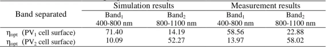
averaged optical efficiency is shown in Table 1, for two separated bands which will be absorbed by two different cells.
Table 1. Average optical efficiency of an off-axis diffractive lens. Band separated
Simulation results Measurement results Band1 400-800 nm Band2 800-1100 nm Band1 400-800 nm Band2 800-1100 nm ηopt (PV1 cell surface)
ηopt (PV2 cell surface)
71.40 10.09 14.19 52.27 58.56 13.97 22.88 58.02 6. Conclusions
In conclusion, the digital diffractive lens that we propose can implement the spectrum splitting of sunlight into two bands, as well as the beam concentration with low concentration factor for lateral multijunction PV cell applications. This lens can be initially fabricated from cheap material by using traditional photolithography techniques, and could be easy integrated into a compact PV cell system.