HAL Id: hal-01356998
https://hal.inria.fr/hal-01356998
Submitted on 19 Sep 2016
HAL is a multi-disciplinary open access
archive for the deposit and dissemination of
sci-entific research documents, whether they are
pub-lished or not. The documents may come from
teaching and research institutions in France or
abroad, or from public or private research centers.
L’archive ouverte pluridisciplinaire HAL, est
destinée au dépôt et à la diffusion de documents
scientifiques de niveau recherche, publiés ou non,
émanant des établissements d’enseignement et de
recherche français ou étrangers, des laboratoires
publics ou privés.
High Performance in the Cloud with FPGA Groups
Anca Iordache, Guillaume Pierre, Peter Sanders, Jose Gabriel de F. Coutinho,
Mark Stillwell
To cite this version:
Anca Iordache, Guillaume Pierre, Peter Sanders, Jose Gabriel de F. Coutinho, Mark Stillwell. High
Performance in the Cloud with FPGA Groups. 9th IEEE/ACM International Conference on Utility
and Cloud Computing (UCC 2016), Dec 2016, Shanghai, China. �hal-01356998�
High Performance in the Cloud
with FPGA Groups
Anca Iordache
Guillaume Pierre
IRISA / University of Rennes 1
Peter Sanders
Maxeler Technologies
Jose Gabriel de F. Coutinho
Mark Stillwell
Imperial College London
Abstract—Field-programmable gate arrays (FPGAs) can of-fer invaluable computational performance for many compute-intensive algorithms. However, to justify their purchase and ad-ministration costs it is necessary to maximize resource utilization over their expected lifetime. Making FPGAs available in a cloud environment would make them attractive to new types of users and applications and help democratize this increasingly popu-lar technology. However, there currently exists no satisfactory technique for offering FPGAs as cloud resources and sharing them between multiple tenants. We propose FPGA groups, which are seen by their clients as a single virtual FPGA, and which aggregate the computational power of multiple physical FPGAs. FPGA groups are elastic, and they may be shared among multiple tenants. We present an autoscaling algorithm to maximize FPGA groups’ resource utilization and reduce user-perceived computa-tion latencies. FPGA groups incur a low overhead in the order of 0.09 ms per submitted task. When faced with a challenging workload, the autoscaling algorithm increases resource utilization from 52% to 61% compared to a static resource allocation, while reducing task execution latencies by 61%.
I. INTRODUCTION
Field-programmable gate arrays (FPGAs) offer invaluable computational performance for many compute-intensive algo-rithms. They are becoming increasingly popular in the high-performance computing community for their excellent com-putation density, performance/price and performance/energy ratios [1]. FPGAs are 40 times faster than CPUs at pro-cessing some of Microsoft Bing’s algorithms [2], and they are commonly used in domains a diverse as financial data processing [3], signal processing [4], and DNA sequence alignment [5]. Intel recently purchased Altera (the biggest FPGA manufacturer) for $16.7bn, and it expects that 1/3 of cloud service provider nodes will use FPGAs by 2020 [6].
To justify the purchase and administration costs of such devices it is necessary to maximize resource utilization over their expected lifetime. However, maximizing utilization may be difficult for many applications whose computation needs are well below the capacity of one FPGA, or whose workload intensity significantly varies over time. The owners of such applications are therefore likely to ignore the benefits of FPGAs and prefer less efficient but more flexible solutions.
We claim that making FPGAs available in a cloud envi-ronment would lower the barrier and make them attractive to new classes of applications. For example, FPGAs can be programmed to execute the AdPredictor click-through rate prediction algorithm [7] orders of magnitude faster than its
counterpart implementations based on CPUs [8]. A personal-ized advertisement service using this algorithm could exploit this performance to process incoming new facts in real-time to continuously adapt its recommendations to any change in user behavior. However, simply providing entire physical FPGAs attached to a virtual machine instance (similar to the GPU-enabled instance types proposed by Amazon Web Services) would not be sufficient, as the workload of a personalized advertisement service may vary considerably over time. Max-imizing the FPGA utilization therefore requires one to deliver elastic processing capacities ranging from fractions of a single device’s capability to that of multiple devices merged together. Turning complex FPGA devices into easy-to-use cloud resources requires one to address two main issues. First, programming FPGAs requires skills and expertise. FPGAs are essentially a set of logical gates (AND, OR, NOT) which can be dynamically wired programmatically. The best perfor-mance is obtained when the FPGA design closely matches the data-flow logic of the program itself, following a pipelined architecture. Circuit designs are typically compiled from high-level programming languages, but this process requires specific skills and experience [9]. While this is not a major issue for large organizations willing to invest massively in FPGA technologies, it may be a significant hurdle for smaller users. The second issue is the lack of satisfactory techniques for virtualizing FPGAs. Current solutions are based either on stati-cally partitioning the gate array between multiple applications (i.e., sharing in space), or on naive context switching (i.e., sharing in time). As discussed in Section II, both techniques exhibit significant problems: sharing in space implies that each application must use a smaller number of digital gates, thereby negatively impacting performance. Conversely, naive time sharing incurs prohibitive context-switching costs, as reconfiguring an FPGA from one circuit design to another takes in the order of a couple of seconds.
To become fully integrated as regular cloud resources, virtual FPGAs should exhibit the following properties: Management. FPGAs should expose an abstract interface that
allows them to be managed by the cloud platform, including tasks such as allocation, deallocation, deployment, execution, and resource utilization monitoring.
Programmability. Once FPGAs have been provisioned to cloud tenants, they should be programmable to tailor their application needs, similar to CPU compute resources.
Sharing. Like other types of cloud resources, FPGAs should allow the same physical device to be shared by multiple tenants in order to maximize resource utilization.
Accessibility. To facilitate sharing, FPGAs should not only be made available to virtual machines executing on the same host. Rather, they should be organized as a pool of resources remotely accessible from any host.
Performance. To retain the high performance/price ratio of physical FPGAs, the performance overhead of FPGA virtu-alization should remain minimal.
High utilization. When multiple virtual FPGAs compete for a limited set of physical resources, the processing capacity of physical FPGAs should be dynamically assigned to the virtual FPGAs which need it the most.
Isolation. Sharing resources requires that each resource in-stance is completely isolated from each other, not allowing tenants to access each other’s data through the shared device. We propose the notion of FPGA groups. An FPGA group is composed of one or more physical FPGAs which are configured with the exact same circuit design. By load-balancing incoming execution requests between its members, an FPGA group may be considered by its clients as a virtual
FPGAwith aggregates the computational capacity of multiple
physical FPGAs. FPGA groups are elastic, as one can easily add or remove physical devices to/from a group. An FPGA group may, for example, be created by a cloud tenant whose computational needs exceed the capacity of a single FPGA.
FPGA groups may also be shared among multiple tenants who wish to use the same circuit design. Although this condition is very unlikely in the case where tenants compile their own circuit designs from custom code, we claim it is realistic in the case of circuit designs chosen from a standard library. Such a library would typically contain highly-optimized circuits for common types of functions in domains such as data analysis (with functions such as regression, correlation and clustering), multimedia (with functions such as video encoding and fast Fourier transform), and machine learning (with functions for Bayesian and neural networks).
Finally, multiple FPGA groups may also compete for the use of a limited set of physical devices. In this case, we present an autoscaling algorithm which dynamically assigns FPGAs to FPGA groups. This algorithm maximizes FPGA utilization (which improves the cloud provider’s revenues), while reducing individual task execution times in most cases. The key novelty in this work is that virtual FPGAs can time-share a pool of physical FPGAs, which grows or shrinks dynamically in response to load. Cloud tenants view a virtual FPGA as a single device which encompasses all its logic resources and memory, which may be backed by multiple physical FPGAs at runtime. Cloud tenants simply load their circuit once to create static or self-managed elastic groups.
Our experiments show that FPGA groups incur a low overhead in the order of 0.09 ms per task, while effectively aggregating the processing capacity of multiple FPGAs. When faced with a challenging workload, our autoscaling algorithm increases resource utilization from 52% to 61% compared to
a static resource allocation, while reducing the average task execution latency by 61%.
This paper is organized as follows. Section II introduces the state of the art. Section III presents the design of FPGA groups, and Section IV discusses elasticity and autoscaling. Finally, Section V evaluates our work and Section VI concludes.
II. STATE OF THE ART
A. FPGA primer
FPGAs are semiconductor devices organized as two-dimensional or three-two-dimensional arrays of Configurable Logic Blocks (CLBs) [10]. Each CLB is an elementary circuit which can be programmatically configured to realize a variety of simple logical functions, such as AND/OR/NOT digital gates, flip-flops and 1-bit full adders. The interconnection between CLBs is highly reconfigurable as well, allowing one to realize any digital electronic circuit — within the size limits of the gate array — by proper reconfiguration of the CLBs and their interconnection matrix. FPGA boards are often also equipped
with external memory and a PCI Express R interface for
high-performance communication with their host machine. FPGA circuit designs are usually implemented using hard-ware description languages such as Verilog and VHDL, which operate at a very low level of abstraction using logic elements such as digital gates, registers and multiplexors. These de-scriptions can also be automatically derived from higher-level programming languages similar to C, Java or OpenCL [9], [11]. However, to obtain the best possible performance, FPGA programmers must still have a deep understanding of the mapping between a high-level program and its low-level trans-lation, and annotate their code with appropriate optimization guidelines [12]. Efficient programming of FPGAs therefore requires specific training and experience, which effectively creates a barrier to entry for new developers to exploit the full potential of FPGAs. For this reason, FPGA manufacturers propose highly-optimized off-the-shelf libraries for specific computations. Although many of these libraries are domain-specific, they can also provide generic functions such as various types of data analysis computations, multimedia pro-cessing, and machine learning [13], [14].
FPGAs can outperform CPU-based compute resources by at least one order of magnitude while running at considerably lower clock frequencies due to the fact that the physical orga-nization of a hardware design can closely match the dataflow logic of the implemented algorithm and be implemented in a deep pipelined architecture. This allows multiple function executions to operate in parallel over different parts of the gate array, providing high-throughput performance. A typical usage pattern therefore consists for a client program to issue large batches of task execution requests which can then be efficiently pipelined by the FPGA.
B. Integrating FPGAs in virtualized environments
Client programs running on traditional machines typically use an FPGA as a co-processor device. Applications access the FPGA via local library functions designed to translate function
Fig. 1: Local and remote virtualization of accelerators; (a) using PCI passthrough; (b) using API remoting locally; and (c) using API remoting remotely.
calls to batches of asynchronous task execution requests issued via the PCIe bus.
Integrating FPGAs in a virtualized environment requires one to rethink the communication between the client program within a virtual machine, and the FPGA. Ideally, this commu-nication should exhibit as little overhead as possible so as not to reduce the interest of using accelerators. It should also allow any VM to make use of any FPGA device, regardless of the physical location of the VM and the FPGA. There exist three main techniques for this, which have been applied either to support access to FPGAs or GPGPUs (the issues and solutions being very similar for both types of devices).
I/O passthrough exposes the accelerator to a virtual ma-chine running on the same server using the ‘passthrough’ feature supported by all modern hypervisors [15]. This technique, illustrated in Figure 1(a), is for example used by Amazon EC2 to create GPU-enabled virtual machine instances [16]. I/O passthrough delivers performance levels similar to the native capacity of the PCI bus. However, it restricts the usage of an accelerator only to the VMs running on the same host. In addition, it currently does not allow multiple co-located VMs to share the same physical FPGA. Paravirtualization allows multiple VMs to share a phys-ical accelerator by providing a device model backed by the hypervisor, the guest operating system and the device driver. Examples of this approach include GPUvm [17] and pvFPGA [18] supporting GPGPUs and FPGAs, respectively. However, this technique suffers from performance overheads and remains limited to sharing the accelerator between VMs running on the same server machine.
API remoting, shown in Figure 1(b), allows multiple appli-cations to use a common accelerator API such as OpenCL or CUDA. Calls to the API are intercepted in the VM and passed through to the host OS on which the accelerator is accessible. Each VM appears to have exclusive access to the accelerator and software on the host to resolves any contention. A number of technologies employ API remoting in a tightly coupled systems including vCUDA [19],
gVir-tuS [20] and LoGV [21]. In such a case the issue of sharing becomes one of scheduling and the applications obtain a fraction of the accelerator dependent on the other users and the scheduling algorithm employed.
API remoting also allows accessing a (possibly shared) accelerator remotely, as shown in Figure 1(c). In this case, the choice of network technology becomes very important as it can become the dominating performance factor. The advent of high-speed networks such as Infiniband which have bandwidths similar to that of PCI provide a solution by enabling the use of accelerators on separate nodes to the host application. A number of technologies employ API remoting over a network including rCUDA [22], DS-CUDA [23], dOpenCL [24] and VirtualCL [25]. Additional studies with Infiniband networks show that this is a practical solution for rCUDA [26] and DS-CUDA [27].
C. Related work on FPGA virtualization
Allowing cloud tenants to reserve fractions of an FPGA’s processing capacity requires a cloud operator to share FPGA devices among multiple tenants. Most of the research on ac-celerator virtualization is focused on the many-to-one solution where several applications share a single accelerator, since the accelerator is the expensive device that needs to be shared. Sharing in space consists in running multiple independent
FPGA designs (possibly belonging to different tenants) next to each other in the gate array. This is made possible by a technique called partial reconfiguration where the FPGA area is divided in multiple regions, allowing each region to be reconfigured with a particular circuit design [28], [29]. This approach effectively parallelizes the execution of the different designs, and increases the device’s uti-lization. However, space sharing reduces the area that is made available to host an FPGA design, which can have a considerable performance impact because it limits the number of functional units that can work in parallel. Sharing in space also requires some switching logic in the FPGA to route incoming requests to the appropriate design, which can add additional overhead.
Sharing in time consists in executing a single FPGA design at any point of time, but of switching the FPGA usage from tenant to tenant over time (similarly to operating system process-level context switching). This approach is often overlooked in the FPGA community due to the very high reconfiguration costs from one design to another: a naive implementation would impose prohibitive context switching costs in the order of a couple of seconds.
The shared FPGA groups proposed in this paper belong to the sharing-in-time category. In order to avoid issuing costly FPGA reconfigurations each time a new task is submitted, shared FPGA groups retain the same configuration across large numbers of task submissions, and incur reconfiguration costs only when an FPGA needs to removed from one group and added to another. Apart from this infrequent operation, tasks submitted by multiple tenants can therefore execute with no reconfiguration delay.
TABLE I: A summary of related work.
Approach Accel.type Sharing method Access Sharingtype Amazon EC2 [16] GPGPU PCI passthrough Host Many-to-one GPUvm [17] GPGPU Paravirt. Host Many-to-one pvFPGA [18] FPGA Paravirt. Host Many-to-one vCUDA [19] GPGPU API remoting Host Many-to-one gVirtuS [20] GPGPU API remoting Host Many-to-one rCUDA [26] GPGPU API remoting Network Many-to-one DS-CUDA [27] GPGPU API remoting Network Many-to-one [28], [29] FPGA Partial reconf. Host Many-to-one FPGA groups FPGA Time-Sharing Network Many-to-many
A summary of related work is presented in Table I. These approaches focus on many-to-one scenarios allowing multiple VMs to share a single FPGA. To our best knowledge, our approach is the first method which also considers the one-to-many and the one-to-many-to-one-to-many situations where an application may use a single (virtual) accelerator which is backed by multiple physical FPGAs.
III. FPGAGROUPS
A client application using FPGAs usually executes on a host that has an FPGA board connected via a dedicated bus, such
as PCI Express R. The application must first reconfigure the
FPGA with a specific design which provides the appropriate function, and then perform a sequence of I/O operations on the FPGA, including initializing static data on the FPGA, streaming input data to it, and streaming results from it. The computation is performed on the data as it flows through the logic of the FPGA design.
However, in this architecture the FPGAs are accessible only to applications running on the host machine, which limits the number of applications that can share the FPGAs. To support full many-to-many mapping between FPGAs and the VMs accessing them, our solution is to co-locate a number of FPGAs in so-called “MPC-X” appliances which can be communicated with using the API remoting technique over an Infiniband network [30]. This solution allows the client applications to run on regular servers and use FPGAs remotely on the MPC-X appliance.
A. The MPC-X Appliance
Figure 2 provides an overview of an MPC-X. In this setup, tasks and results are sent to the appliance across an Infiniband network. This network technology is particularly suitable for such usage thanks to its low packet latency, and RDMA support which avoids unnecessary data copying within the MPC-X.
The switch fabric of the MPC-X manages the arrival and execution of tasks on the appropriate FPGA. Although it would seem natural to implement it in software, and to execute it in a standard processor within the MPC-X device, such design is likely to incur significant performance overheads without RDMA support [30], [31]. Instead, the MPC-X implements the switch fabric directly in hardware. As it is only concerned with the efficient execution of tasks on FPGAs, it can be designed solely for this purpose so its performance is not be impacted by the side effects of running the application’s CPU code.
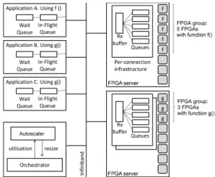
Fig. 3: System architecture with three application VMs and
two MPC-X’s. Application A uses function f() provided by a
group of five FPGAs. Applications B and C share a group of three FPGAs supplying function g().
RAM 48GB FPGA RAM 48GB FPGA RAM 48GB FPGA
...
In fin ib an d ne tw or k Switch fabricFig. 2: An MPC-X with eight FPGAs and two Infiniband inter-faces.
We envisage that
a cloud infrastructure
supporting FPGAs in a multi-tenant environment will consist of multiple
MPC-X appliances
interconnected with
(some of) the CPU
machines using
Infiniband networks.
Each MPC-X provides
a number of FPGA
devices accessible to any CPU client machine via the Infiniband network.
Our MPC-X
appliances include
eight FPGAs — each equipped with 48 GB of RAM — and two Infiniband interfaces to overcome any bandwidth limitation of the Infiniband connection.
B. Resource Management
MPC-X’s and physical FPGAs are passive hardware de-vices. They have no operating system nor embedded software that can handle even basic resource management operations such as allocating/deallocating FPGAs, sharing them between applications, and establishing a connection with authorized client programs.
These operations are handled by a software component called the Orchestrator, as shown in Figure 3. The Orchestrator runs in a regular server machine connected to the same Infini-band network as the MPC-X’s and the client machines. Similar to cloud resource manager services such as OpenStack Nova, the Orchestrator is in charge of maintaining the reservation state of each FPGA, including whether it is currently reserved and by which tenant. When a client reserves one or more
(physical) FPGAs, the Orchestrator chooses available FPGAs, updates their reservation state, and returns a handle to the client containing the address of the MPC-X it belongs to and a local identifier. The Orchestrator is also in charge of managing the FPGA groups, as we discuss next.
C. FPGA Groups
A client application which requires the combined processing capacity of multiple FPGAs can obviously reserve the devices it needs, configure all FPGAs with the same design, and load-balance its task execution requests across them. However, this introduces complexity in the application as it would need to decide how many FPGAs to request and then load balance the tasks across those FPGAs. Sharing these FPGAs across multiple client machines is even more challenging.
We propose a virtualization infrastructure using so-called FPGA groups. An FPGA group presents itself to an application as a single virtualized FPGA. However this virtual computa-tional resource can be backed by a pool of physical FPGAs that perform the actual computation. All the FPGAs within the group are configured with the same hardware design. The client application submits tasks to the virtual FPGA in exactly the same way it would of a single physical FPGA.
As shown in Figure 3, in our current implementation, an FPGA group resides entirely within a single MPC-X. When the Orchestrator receives a request to create a new group, it allocates the required number of FPGAs within one MPC-X. It then sets up a new receive (Rx) buffer to hold the arriving tasks requests and a number of queues equal to the number of physical FPGAs in the MPC-X (regardless of the number of FPGAs assigned to this group). A new set of Rx buffer and queues is created each time a new client application wants to use the FPGA group, and deleted after the client application terminates. For example, in Figure 3, the FPGA group holding function g() is shared between application B and application C; each application access its own Rx buffer and queues in the FPGA server.
On the application side the group is represented as a fixed-size in-flight queue which holds references to the tasks that are being processed on the MPC-X. There is also a wait queue which stores the waiting tasks.
We carefully designed this organization to minimize the task-submission overhead. Each application can submit its own tasks from the client-side wait queue to the group-side queues with no interference with other clients. When a task arrives in the MPC-X’s Rx buffer, the MPC-X places the tasks into the task queue with the shortest length. The request is then placed into the task queue with the shortest length.
Creating as many task queues as there are FPGAs in the MPC-X implies that the number of task queues is always greater or equal to the number of FPGAs in a group. This allows (as we discuss in the next section) to minimize the time taken to dynamically scale the group at runtime. When a queue has at least one task to execute, it attempts to lock an FPGA from the pool of FPGAs in the group. When a lock has been obtained, the task is executed on the corresponding
FPGA. After execution, the FPGA is unlocked and the task result is sent back to the application. Thus, each queue has a simple and sequential behavior. Note that tasks in the same task queue do not necessarily execute on the same FPGA.
An additional benefit of creating a separate Rx buffer per client application is that it makes it easy to revoke an application’s access to the FPGA group, for example if the tenant decides to stop using a shared FPGA group.
D. Discussion
Memory isolation. One important issue for virtual FPGAs is memory isolation between multiple independent tasks running simultaneously in the same FPGA group, but po-tentially belonging to different tenants. FPGAs do not have Memory Management Units (MMUs) nor kernel/userspace separation, which makes it impossible for them to page memory the same way CPU-based servers do. When an FPGA group is used by a single user (e.g., to serve tasks issued by an elastic set of VMs), the FPGA group will consider all incoming tasks as if they had been issued by a single VM. In multi-tenant scenarios, our system currently does not address isolation issues. As a consequence, we restrict this multi-tenant scenario to the use of stateless FPGA designs such as signal processing and video encoding. Inter-task dependencies. We assumed so far that tasks are independent from each other: this allows us to execute incoming tasks in a worker thread-pool pattern. However, one may for example want to stream large amounts of data and to perform statistical analysis across multiple tasks. To address these issues, a client can send a pseudo-task to the FPGA group which performs a ‘lock’ function. This then reserves a queue and its associated FPGA exclusively for this client until the ‘unlock’ function is sent. Obviously, we can lock only a finite number of concurrent times – i.e., the number of FPGAs.
Orchestrator scalability. Although we represented the Or-chestrator (and the Autoscaler introduced in the next section) as a single server in our architecture, they maintain very simple state which may be stored in a fault-tolerant key-value store: for each FPGA group they essentially store a copy of the circuit design (which represents about 40 MB per design) and the list of FPGAs which are currently part of the group. This allows for easy replication and/or partitioning across the data-center. In addition, any temporary unavail-ability of the Orchestrator would only impair the unavail-ability to start/delete/resize FPGA groups, without affecting the avail-ability of the existing FPGA groups, or their functionality. Scaling an FPGA group beyond a single MPC-X. There is no fundamental reason why FPGA groups cannot span more than one MPC-X. This is essentially a limitation of our current implementation: spreading FPGA groups across multiple servers would require an additional load-balancing mechanism at the client side, which implies that the client-side library must receive notifications upon every update in the list of MPC-X’s belonging to a group. This feature is currently under development.
IV. ELASTICITY AND AUTOSCALING
What has been described so far uses a fixed number of physical FPGAs in each FPGA group. However this structure allows the easy addition and removal of FPGAs from a group without any disruption to executing tasks or any interaction with the client application. We discuss FPGA group elasticity first, then present our autoscaling algorithm.
A. Elasticity of virtual FPGAs
The design of FPGA groups makes it easy to add or remove FPGAs to/from an FPGA group located in the same MPC-X. All that has to be done is reconfigure the FPGA with the appropriate design and update the load-balancing information in the task queues at the server side. The resized group still presents itself to an application as a single virtualized FPGA, however this virtual computational resource has a varying number of physical FPGAs that will perform the actual computation.
This elasticity allows a cloud provider to place multiple FPGA groups on the same MPC-X and dynamically reassign physical FPGAs to groups according to the demand each group is experiencing, similar to the way hypervisors can dynamically reallocate the CPU shares granted to virtual CPUs. This automatic elasticity is managed by a software component called the Autoscaler, as shown in Figure 3. B. Autoscaling of virtual FPGAs
The workload incurred by FPGA groups may significantly vary over time because of workload fluctuations in client applications themselves, as well as the arrival or departure of client applications making use of each group. Increasing the number of applications using the same group raises the contention of the FPGAs in the group and consequently it affects the performance of individual applications. The Autoscaler monitors the resource utilization of each group and periodically rebalances the number of FPGAs assigned to each group.
The aim of this algorithm is to maximize the infrastructure utilization while improving the overall application completion time. Therefore, more applications get access to the FPGAs, which in turn is also beneficial for the cloud provider.
The Autoscaler periodically computes the average task runtime for each FPGA group (defined as the sum of the queuing time and the processing time). It then resizes the groups to minimize the average runtime across all groups which share the same MPC-X.
Note that resizing FPGA groups is an expensive operation, as it requires to reconfigure one or more FPGAs with a new hardware design. To avoid spending more time reconfiguring FPGAs than using them for processing incoming tasks, the periodicity (currently set by the adminstrators) at which group size is updated should be at least an order of magnitude greater than the reconfiguration time, which we have observed to be in the order of a few seconds in our appliances (see Section V). The Autoscaler periodically computes the total queue length per client application and per FPGA group. A group with
t1 t2 t3 Client2 Client3 Client1 r1 r3 r2
G1 FPGA FPGA FPGA FPGA FPGA FPGA G2
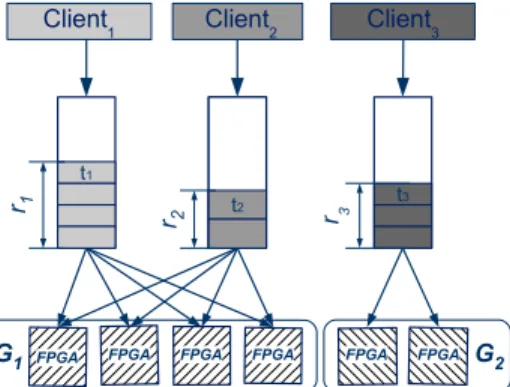
Fig. 4: Two FPGA groups receiving tasks and the server-side task queues (client-side queues are omitted as they do not participate in the autoscaling algorithm).
empty task queues is scaled down to the minimum working size of one FPGA, allowing other groups to utilize the idle FPGAs. When not enough FPGAs are available to satisfy all the demands, the Autoscaler balances the groups by assigning FPGAs in proportion to their workloads.
Figure 4 shows the metrics of interest in FPGA group
scal-ing. Tasks from applications can have a different runtime ti.
We define T as the total runtime of all tasks in an application’s
queue Q corresponding to a group G: T = t× size(q).
The total processing time for all tasks submitted to a group G is the sum of the total processing time of all the queues in
the group: RG=P Ti.
The objective of the autoscaler is to balance the overall completion times for the n groups sharing FPGAs of the same MPC-X. This is achieved by minimizing the mean of absolute
values of RGi differences: minimize n X i=1 n X j=1 | RGi− RGj | n2
Solving this optimization problem requires knowing the size of the queues using a group and the runtime t of every task. The information concerning the number of tasks in the queue can be retrieved periodically from the Orchestrator. On the other hand, the runtime of a task is unknown in the system. In order to determine it we rely on the periodical measurements the Autoscaler is retrieving from the Orchestrator. These measurements express how many tasks of each type have been executed in the measuring interval. Aggregating this information for several measurements helps in building a linear equation system where the unknown variables are the runtimes of tasks corresponding to the queues connected to a FPGA group and the coefficients are the number of tasks executed in one measurement interval.
The resulting system for one group is as follows: A11× t1 + A12× t2 + · · · + A1n× tn = I A21× t1 + A22× t2 + · · · + A2n× tn = I · · · Am1× t1 + Am2× t2+ · · · + Amn× tn = I
Algorithm 1 Autoscaling Algorithm
Input: Groups G = {G1, G2, . . . , Gn}
Output: Group sizes Snew
1: I = scaling interval (e.g. 10s)
2: S ← {S1, S2, . . . , Sn} where Siis the current size of Gi∈ G
3: initialize Snew= {0, 0, · · · , 0}
4: for i = 1 to |G| do
5: A ← {A1, A2, . . . , An} number of executed tasks for each
queue of group Giin the last measurement interval I
6: T ← {T1, T2, . . . , Tn} total runtime estimates for Ai on Gi
of size Si using NNLS
7: t ← {Tj/Si} for j ∈ {1 . . . n} runtime estimate of Tj on
single FPGA
8: TW ← tasks waiting to be executed on Gi
9: Ri←P TW × t required processing time for Gi
10: Snew← {Ri×Pnj=0Sj
Pn
j=0Rj } for i ∈ {1 . . . n}
11: return Snew
where:
n = number of applications using the group;
m = number of past measurements of task execution;
I = measuring interval;
ti = task runtime corresponding to queue i;
Aij= number of executed tasks of type j in the interval i
Note that the Autoscaler builds a system for each group.
In order to solve the system and calculate the runtimes ti
we apply a non-negative least-squares (NNLS) algorithm [32]:
given an m× n matrix A and an m-vector I, the algorithm
computes an n-vector T that solves the least squares problem
A× T = I , subject to T ≥ 0.
Solving the linear system provides an approximation of the task runtimes which are then used in calculating the total processing time required of a group. The Autoscaler then assigns an FPGA share proportional to the demand on each group. The scaling algorithm is presented in Algorithm 1.
This algorithm tries to treat all applications as fairly as possible in order to minimize the overall runtime of the current workload. An extension to this work might rather prioritize certain applications that are considered more valuable.
V. EVALUATION
We now evaluate the performance of FPGA groups con-sidering two perspectives: (i) the cloud provider’s interest to maximize resource utilization and accommodate as many client applications as possible; and (ii) client applications aiming to minimize the runtime and cost of their tasks.
Our experiments are based on a single MPC-X equipped with eight ALTERA STRATIX-V FPGAs and two Infiniband interfaces which load-balance the workload between appli-cations and the appliance. The Orchestrator distributes the workload by selecting which connection an application should use to access the MPC-X at load time. Latency measurements were issued at the client side while utilization measurements were done by querying the MPC-X’s public API.
In our experiments, the average time to configure the FPGA
when resizing a group is3.78 s± 0.13, but the actual time for
0 100 200 300 400 500 600 Time (s) 0.5 1.0 1.5 2.0 2.5 3.0 Latency (ms) P hysical F P GA V irtual F P GA
(a) Task execution delays
0.0 0.5 1.0 1.5 2.0 2.5 Latency (ms) 0 1 2 3 4 5 6 Probability density 0.78 0.87 0.33 Task runtime P hysical F P GA V irtual F P GA
(b) Statistical distribution of task execution delays
Fig. 5: FPGA virtualization overhead.
moving an FPGA from one group to another is slightly larger because of the need to wait until currently-running tasks have finished executing. The Autoscaler is configured to re-evaluate the FPGA group sizes every 10 seconds. An additional server machine submits tasks to the FPGAs.
A. Virtualization overhead
We first evaluate the performance overhead due to the FPGA group mechanisms. We submit a simple task workload to a single FPGA so that it does not overload the FPGAs: the client issues one task requiring 0.33 ms every second.
Figure 5 compares the task execution latency when the application addresses a single non-virtualized FPGA (without FPGA groups) and a virtualized FPGA group composed of a single FPGA. We can see that, even in the fastest case, the client-side task submission and network transfers between the client machine and the FPGA add a total execution latency in the order of 0.45 ms. This is the reason why FPGA pro-grammers typically submit task execution requests in batches so they incur the network overhead only once for the whole batch rather than once per task.
We can also see the performance overhead due to virtual-ization: the latency of tasks submitted to the virtual FPGA is on average 0.09 ms greater than when submitted to the physical FPGA. This difference is due to the additional queues introduced by FPGA groups. We can however note that virtualization does not increase the variability of execution latencies compared to a non-virtualized scenario.
0 1 2 3 4 5 6 7 8 FPGA Group Size
10−1 100 101 102 103 A verage Latency (ms) 1500 tasks/s 3000 tasks/s 6000 tasks/s
Fig. 6: Effects of FPGA group elasticity.
B. FPGA group elasticity
We now evaluate the effectiveness of FGPA group elas-ticity to handle large task execution workloads. We issued a constant load of 1500 tasks/second, 3000 tasks/second or 6000 tasks/second to FPGA groups of various sizes. Each task has an execution time on the FPGA of 1 ms.
Figure 6 shows the effect of varying the FPGA group sizes when handling these workloads. The smallest workload (1500 tasks/second) can in principle be handled with two FPGAs. When using only one FPGA, task execution requests pile up in the queues: execution latencies are very high, with very high variability. However, with a group of size 2, the task execution latency decreases to roughly 0.64 ms, with almost no variability. When increasing the group size further, the average task execution latency decreases even further down to 0.23 ms. Similar behavior happens with larger workloads: when the FPGA group is too small to handle the incoming stream of task execution requests, task execution latencies are very high, with large standard deviation. When the group becomes sufficiently large to handle the tasks, latencies decrease drastically with very low standard deviation.
This demonstrates that FPGA groups can actually aggregate the processing capacity of multiple physical FPGAs. Varying the group size effectively allows one to control the capacity of the virtual FPGA, while keeping these operations totally invisible for the client application.
C. FPGA group autoscaling
We now evaluate the FPGA group autoscaling algorithm using three synthetic applications that can be executed using FPGA groups which compete for resources:
Application A consists of tasks which require 0.33 ms of execution time. This mimics the behavior of a Fast Fourier Transform operated over a buffer of 262,144 double-precision values. To maximize execution efficiency, tasks are submitted in batches of 300 tasks.
Application B is a scaled-up version of application A where tasks require 1 ms of execution time. Here as well, tasks are sent by batches of 300 tasks.
Application C consists of long-running tasks such as video encoding which require 100 ms of execution time. Tasks are sent by batches of 3 tasks.
Figure 7 compares the behavior and performance of static-size and autoscaled FPGA groups based on two workload sce-narios. For both figures the static-size groups were provisioned with two FPGAs for application A, four for application B, and two for application C. We chose these numbers such that the group sizes would be proportional to the total workload execution time of each application.
Figure 7a shows a scenario with a light workload where the FPGA server has more than enough resources to process all incoming requests, despite workload variations in applications A, B and C (depicted in the top part of the figure). In this situation, the static FPGA allocation reaches an average resource utilization of 32%, while keeping low individual batch execution latencies (on average 0.43 s per batch).
In this scenario where no group resizing is necessary, the autoscaling system incurs the overhead of FPGA group recon-figuration while having nothing to gain from this operation. It would be very easy to adjust Algorithm 1 so that it refrains from any resizing operation when all current queue lengths are small enough. We however decided to let the Autoscaler overreact to workload variations to highlight the overhead of FPGA group reconfiguration.
The bottom half of Figure 7a shows the resizing deci-sions taken by the Autoscaler, and their impact on resource utilization and batch execution latency. We see a spike in execution latency each time an significant resizing operation takes place. The reason for this is threefold: first, upon any reconfiguration there is a period of several seconds during which fewer FPGAs are available to process batch execution requests; second, the FPGA group which gets shrunk may not have sufficient resources to process its workload, so requests queue up until the next resizing operation where the group size may be increased again; and, finally, in this particular experiment these unavoidable costs are not compensated by any benefits from the useless rescaling operation.
Figure 7b shows a scenario with twice as much workload as previously. Here, the static FPGA groups cannot efficiently process all incoming requests. In particular, application A does not have enough resources to handle its peak workload, so batch execution latencies for application A grow substantially, up to 22 s per batch. On the other hand, during peak activity of application A, application B underutilizes its own resources so the obvious solution is to temporarily reassign FPGAs from application B to application A. This is exactly what the Autoscaler does in this case. As a result, application A now shows much better performance, at the expense of slightly slowing down application B. Interestingly, between times 150 s and 200 s, both applications A and B experience high workloads, which together exceed the total processing capacity of the system. In this situation, the Autoscaler maintains a reasonable fairness between all applications.
These experiments highlight the interest of dynamically re-sizing FPGA groups in situations where multiple applications compete for limited resources. On the one hand, autoscaling increases the average resource utilization from 52% to 61%, which allows the cloud provider to process more workload
2 4 6 8 10 Submitted Jobs/sec . A B C 50 100 StaticGroups Utilisation(%) 32.53% ± 18.02 Time (s) 2 4 6 StaticGroups Job Latency(s) Overall average :0.43s ± 0.15 50 100 ElasticGroups Utilisation(%) 38.05% ± 19.12 Time (s) 2 4 6 ElasticGroups Job Latency(s) Overall average :0.59s ± 0.64 0 100 200 300 400 500 600 Time (s) 0 2 4 6 8 ElasticGroups Size (a) Lo w w orkload 5 10 15 Submitted Jobs/sec . A B C 50 100 StaticGroups Utilisation(%) 51.94% ± 23.24 Time (s) 5 10 15 20 StaticGroups Job Latency(s) Overall average :6.49s ± 6.68 50 100 ElasticGroups Utilisation(%) 60.91% ± 28.59 Time (s) 5 10 15 20 ElasticGroups Job Latency(s) Overall average :2.55s ± 2.76 0 100 200 300 400 500 600 Time (s) 0 2 4 6 8 ElasticGroups Size (b) High w orkload Fig. 7: FPGA group autoscaling
with the same resources. Using static groups only, the adminis-trator of application A would probably rather decide to reserve additional FPGAs to handle high-workload scenarios. On the other hand, the Autoscaler benefits the tenants by reducing the average batch execution latency by 61%, from 6.49 s to 2.55 s, thanks to a better usage of these resources.
VI. CONCLUSION
FPGAs have the potential of complementing the current landscape of accelerator devices for high-performance compu-tations. When applied to suitable problems, they deliver excel-lent performance, computational density and energy consump-tion. However, currently FPGAs remain limited to scenarios where a single device is attached to one client application. Maximizing FPGA utilization in such conditions is not easy.
We proposed to virtualize FPGAs as a way to increase their usage flexibility. With FPGA groups, one can create virtual FPGAs which aggregate the processing capacity of one or more physical FPGAs. FPGA groups can be resized manually or automatically to maximize device utilization and further improve user’s experience. FPGA groups can be used by a single tenant, or shared between multiple tenants. However, to isolate tenants from each other, this second scenario should be limited to stateless FPGA designs, i.e., designs that do not keep state from one job to another.
We envisage that cloud operators may exploit FPGA groups in two different ways. An Infrastructure-as-a-Service cloud may augment its compute resource offering by providing FPGA-groups as a service that any tenant may create, resize and use as they wish. Alternatively, a Platform-as-a-Service cloud may use shared FPGA groups to offer efficient high-level computation services for standard algorithms such as Fast Fourier transform, machine learning and video compression, similar to the “Amazon Machine Learning” service provided by Amazon Web Services [33]. Users of these services would not even realize that FPGAs are processing their API calls. Enjoying the performance benefits of FPGA groups using a pay-as-you-go model, and without having to master their com-plex programming model, would arguably help democratize FPGA-based high performance in the cloud.
REFERENCES
[1] S. Sirowy and A. Forin, “Wheres the beef? Why FPGAs are so fast,” Microsoft Research, Tech. Rep. MSR-TR-2008-130, 2008.
[2] R. McMillan, “Microsoft supercharges Bing search with programmable chips,” Wired, 2014, http://www.wired.com/2014/06/microsoft-fpga/. [3] S. Parsons, D. E. Taylor, D. V. Schuehler, M. A. Franklin, and R. D.
Chamberlain, “High speed processing of financial information using FPGA devices,” U.S. patent US7921046 B2, 2011, https://www.google. com/patents/US7921046.
[4] R. Woods, J. McAllister, Y. Yi, and G. Lightbody, FPGA-based Imple-mentation of Signal Processing Systems. Wiley, 2008.
[5] J. Arram, W. Luk, and P. Jiang, “Ramethy: Reconfigurable acceleration of bisulfite sequence alignment,” in Proc. ACM/SIGDA Intl. Symposium on Field-Programmable Gate Arrays, 2015.
[6] Intel, “Acquisition of altera,” Intel Invester Conference Call Deck, 2015, http://bit.ly/1Q1VBqK.
[7] T. Graepel, J. Q. Candela, T. Borchert, and R. Herbrich, “Web-scale bayesian click-through rate prediction for sponsored search advertising in Microsofts Bing search engine,” in Proc. ICML, 2010.
[8] J. G. Coutinho, O. Pell, E. ONeill, P. Sanders, J. McGlone, P. Grigoras, W. Luk, and C. Ragusa, “HARNESS project: Managing heterogeneous computing resources for a cloud platform,” in Reconfigurable Comput-ing: Architectures, Tools, and Applications. Springer, 2014.
[9] D. F. Bacon, R. Rabbah, and S. Shukla, “FPGA programming for the masses,” ACM Queue, vol. 11, no. 2, 2013.
[10] D. W. Page, “Dynamic data re-programmable PLA,” U.S. patent US 4524430 A, 1985, http://www.google.com/patents/US4524430. [11] J. M. Cardoso and P. C. Diniz, Compilation Techniques for
Reconfig-urable Architectures. Springer, 2009.
[12] P. Grigoras¸, X. Niu, J. G. Coutinho, W. Luk, J. Bower, and O. Pell, “Aspect driven compilation for dataflow designs,” in Proc. ASAP, 2013. [13] Maxeler Technologies, “Maxeler AppGallery,” http://appgallery.maxeler.
com/.
[14] Xilinx Inc., “Applications,” http://www.xilinx.com/applications.html. [15] J. P. Walters, A. J. Younge, D.-I. Kang, K.-T. Yao, M. Kang, S. P. Crago,
and G. C. Fox, “GPU-Passthrough performance: A comparison of KVM, Xen, VMWare ESXi, and LXC for CUDA and OpenCL applications,” in Proc. IEEE CLOUD, 2014.
[16] Amazon Web Services, “EC2: Elastic Compute Cloud,” http://aws. amazon.com/ec2/.
[17] Y. Suzuki, S. Kato, H. Yamada, and K. Kono, “GPUvm: why not virtualizing GPUs at the hypervisor?” in Proc. USENIX ATC, 2014. [18] W. Wang, M. Bolic, and J. Parri, “pvFPGA: accessing an
FPGA-based hardware accelerator in a paravirtualized environment,” in Proc. CODES+ISSS, 2013.
[19] L. Shi, H. Chen, J. Sun, and K. Li, “vCUDA: GPU-accelerated high-performance computing in virtual machines,” IEEE Transactions on Computers, vol. 61, no. 6, 2012.
[20] G. Giunta, R. Montella, G. Agrillo, and G. Coviello, “A GPGPU transparent virtualization component for high performance computing clouds,” in Proc. Euro-Par, 2010.
[21] M. Gottschlag, M. Hillenbrand, J. Kehne, J. Stoess, and F. Bellosa, “LoGV: Low-overhead GPGPU virtualization,” in Proc. FHC, 2013. [22] J. Duato, A. J. Pena, F. Silla, R. Mayo, and E. S. Quintana-Ort´ı,
“rCUDA: Reducing the number of GPU-based accelerators in high performance clusters,” in Proc. HPCS, 2010.
[23] M. Oikawa, A. Kawai, K. Nomura, K. Yasuoka, K. Yoshikawa, and T. Narumi, “DS-CUDA: A middleware to use many GPUs in the cloud environment,” in Proc. SCC, 2012.
[24] P. Kegel, M. Steuwer, and S. Gorlatch, “dOpenCL: Towards a uniform programming approach for distributed heterogeneous multi-/many-core systems,” in Proc. HCW, 2012.
[25] A. Barak and A. Shiloh, “The VirtualCL (VCL) cluster platform,” http: //www.mosix.org/txt vcl.html.
[26] C. Rea˜no, R. Mayo, E. S. Quintana-Orti, F. Silla, J. Duato, and A. J. Pe˜na, “Influence of InfiniBand FDR on the performance of remote GPU virtualization,” in Proc. IEEE Cluster, 2013.
[27] A. Kawai, K. Yasuoka, K. Yoshikawa, and T. Narumi, “Distributed-shared CUDA: Virtualization of large-scale GPU systems for pro-grammability and reliability,” Proc. FCTA, 2012.
[28] S. Byma, J. G. Steffan, H. Bannazadeh, A. L. Garcia, and P. Chow, “FPGAs in the cloud: Booting virtualized hardware accelerators with OpenStack,” in Proc. FCCM, 2014.
[29] F. Chen, Y. Shan, Y. Zhang, Y. Wang, H. Franke, X. Chang, and K. Wang, “Enabling FPGAs in the cloud,” in Proc. CF, 2014. [30] M. Technologies, “New Maxeler MPC-X series: Maximum performance
computing for big data applications,” 2012, http://bit.do/b9ZYX. [31] S. Potluri, K. Hamidouche, A. Venkatesh, D. Bureddy, and D. Panda,
“Efficient inter-node MPI communication using GPUDirect RDMA for InfiniBand clusters with NVIDIA GPUs,” in Proc. ICPP, 2013. [32] Turku PET Centre, “libtpcmodel,” http://www.turkupetcentre.net/
software/libdoc/libtpcmodel/nnls 8c source.html.
[33] Amazon Web Services, “Amazon Machine Learning,” http://aws. amazon.com/aml/.