Ministry of Higher Education and Scientific Research
University of El-Oued
Faculty of Technology
Department of Electrical Engineering
Theses of the End Study
Presented to obtain the diploma of:
ACADEMIC MASTER
Domain : Sciences and Technology
Option : Electrotechnical
Specialty : Electrical Control
Title
Directed by: Realized by:
Dr. BEKAKRA Youcef -Guerfi Khayreddine - Moulay Idris
University Year : 2017/2018
Study and Control of a Stepper Motor using
an Arduino Card
Acknowledgments
Acknowledgments First, we thank God, the Almighty, for giving us the health and the will to do this humble job.
We would like to express our sincere thanks to our promoter Dr BEKAKRAYoucef for the help and for the precious advice he gave us during our study and the realization of this work.
Our thanks to: M. The president and jury members have accepted to judge and evaluate our work.
We also thank all the teachers and teachers, our parents, our brothers and sisters and our dear friends for their help and sacrifices.
Dedicate
We dedicate this humble work.
To those who helped us to do this modest work by their advice and encouragement: • Our parents
• Our supervisor Dr BEKAKRAYoucef • Our teachers
• Our dear friends
• To all the promotion 2017 /2018
i SUMMARY:……….….i Figures LIST:………...…….vii TABLES LIST:….……….…..….x SYMBOLES LIST………..……….xi
Chapter
:
I.1 INTRODUCTION: ... 2 I.2 CONSTRUCTION: ... 2I.3 HOW DOES IT WORK? ... 2
I.4 TYPES OF STEPPER MOTORS: ... 3
I.4.2 Permanent Magnet Stepper Motor: ... 3
I.4.3 Hybrid Stepper Motor: ... 7
I.4.3.1 Unipolar HSM: ... 9
I.4.3.2 Bipolar HSM: ... 9
I.5 CONTROL OF STEPPER MOTORS: ... 9
I.6 COMPARISON OF STEPPER MOTOR TYPES: ... 10
I.7 SELECTION OF MOTOR: ... 12
I.8 CHARACTERISTICS OF STEPPER MOTOR: ... 12
I.8.1 STATIC CHARACTERISTICS: [17] ... 12
I.8.1.1 TORQUE ANGLE CURVE: ... 12
ii
I.8.1.3 DETENT TORQUE (TD): ... 13
I.8.2 DYNAMIC CHARACTERISTICS: ... 13
I.9 DIFFERENT MODES OF EXCITATION: ... 14
I.9.1 Full-Step: ... 14
I.9.2 Half-Step: ... 14
I.9.3 Micro Step Mode: ... 16
I.10 TYPE OF DRIVER: ... 16
I.10.1 UNIPOLAR DRIVER: ... 17
I.10.2 BIPOLAR DRIVE ... 17
I.11 COMPARISON BETWEEN DRIVERS: ... 18
I.12 STEPPER MOTOR APPLICATIONS: ... 18
I.13 ADVANTAGES OF STEPPER MOTORS COMPARED WITH OTHER MOTORS: ... 18
I.14 DISADVANTAGES OF STEPPER MOTOR: ... 19
I.15 CONCLUSION ... 19
Chapter
:
II.1 INTRODUCTION: ... 20II.2 EXPLAIN SOME IMPORTANT MEANING: ... 20
II.2.1 Simulation... 20
II.2.2 MATLAB-SIMULINK: ... 20
iii
II.2.4 Modeling: ... 21
II.2.5 Pulse: ... 22
II.4.1 Mathematical model of HSM: ... 23
II.4.2 Assumptions: ... 25
II.4.3 Stepper Motor Design In MATLAB-SIMULINK: ... 25
II.5.1 Full Stepping Mode: ... 27
II.5.2 Half Stepping Mode: ... 27
II.5.3 Voltage Source: 27 II.6 SIMULATION RESULTS: ... 29
II.6.1 Full Stepping Mode: ... 29
II.6.3 Half Stepping Mode: ... 31
II.6.4 Discussions: ... 33
II.7 COMPARISON: ... 33
II.7.1 Current: ... 33
II.7.1.1 Using Full Step Mode:... 33
II.7.1.2 Using Half Step Mode: ... 34
II.7.2 Speed And Position: ... 34
II.7.2.1 Using Full Step Mode:... 34
II.7.2.1.1 Speed: ... 34
II.7.2.1.2 Position: ... 34
II.7.2.2 Using Half Step Mode: ... 34
II.7.2.2.1 Speed: ... 34
II.7.2.2.2 Position: ... 34
II.7.3 Torque: ... 35
II.7.3.1 Using Full Step Mode:... 35
iv
II.7.4 Voltage: ... 35
II.7.4.1 Using Full Step Mode:... 35
II.7.4.2 Using Half Step Mode: ... 36
II.8 CONCLUSION: ... 36
Chapter
III.1 INTRODUCTION: ... 37III.2 SOME BASIC DEFINITIONS: ... 37
III.2.1 What is a System? ... 37
III.2.2 CONTROL SYSTEM: ... 37
III.2.2.1 Open-Loop Control: ... 38
III.2.2.1.1 The Advantages And The Disadvantages of The Open Loop Control: ... 38
III.2.2.2 Closed-loop Systems ... 39
III.2.2.2.1 Advantages And Disadvantages of The Closed-Loop: ... 39
III.2.2.2.2 Closed-loop System Transfer Function ... 40
III.2.3 Feedback: ... 40
III.3 MANIPULATION: ... 41
III.3.1 Arduino: ... 41
III.3.2 The Easy Driver: ... 42
III.3.3 PID Controller: ... 42
III.3.4 Encoder: ... 43
III.3.5 Encoder Disk ... 45
v
III.3.7 Stepper Motor with Cable: ... 45
III.3.8 MATLAB- SIMULINK:... 46
III.4 PRACTICAL CONTROL OF THE STEPPER: ... 46
III.4.1 The Interconnection of The Hardware Part: ... 46
III.4.2 The Interconnection of The Software Part: ... 47
III.4.3 How to Control the Stepper? ... 47
III.4.4 The PID Controller Parameters: ... 48
III.4.5 The Practical Results: ... 48
III.4.4.1 Using Full Step Mode: ... 49
III.4.4.2 Discussion: ... 49
III.4.4.3 Using Half Step Mode: ... 49
III.4.4.4 Discussion: ... 49
III.4.4.5 Using Micro Stepping Mode: ... 50
III.4.4.6 Discussion: ... 50
III.4.6 Application: ... 51
III.4.6.1 Introduction: ... 51
III.4.6.2 Calculating angles necessary to reach a position on a 2D plane for two robot arms in a row: ... 51
III.5 CONCLUSION ... 54
GENERAL CONCLUSION ... 55
REFERENCES LIS: ... XII
vii
Figures list First chapter:
Figure I.1 Block diagram of stepper motor system Figure I.2 Cross-section of variable reluctance motor
Figure 1.3: Schematic diagram of a two-phase two-pole permanent magnet stepper motor.. Figure I.4 Switching sequence for Fig1. 3
Figure I.5 stepping sequence (half-stepping) for a two-phase two-pole PM step motor for
clockwise rotation.
Figure I.6: Two-phase six-pole permanent magnet stop motor. Figure I.7: Cross-section of HSM.
Figure I.8 Cut view of HSM.
Figure I.9: Open loop control of a stepper motor. Figure I.10: Feedback control of a stepper motor. Figure I.11: Torque- angle curve of stepper motor.
Figure I.12: Torque and detent torque profiles of stepper motor. Figure I.13: Torque Vs Speed curves of stepper motor.
Figure I.14: The switching sequence for the eight-step input (half-step mode). Figure 1.15: Differences in the control modes for stepper motors (left: full step,
right: half step).
FIgureI.16: Phase-current diagram for a stepper motor controller in micro step
mode.
Figure 1.17: Unipolar winding. Figure 1.18: Bipolar winding.
viii
Second chapter:
Figure II.1: modeling system diagram.
FigII.2 the equivalent circuit of a two phase stepping motor. Figure II.3: stepper motor design.
Figure II.4: subsystem contains. Figure II.5: electrical part.
Figure II.6: mechanical part design. Figure II.7: parameter
Figure II.8: impulse generator.
Figure II.9: full step sequence of voltage. Figure II.10: Half step sequence of voltage.
Figure II.11: two phases current wave form using full step mode. Figure II.12: speed and position wave form.
Figure II.13: detail speed and position wave form. Figure II.14: Torque wave form.
Figure II.15: detail tow phase voltage V(A),V(b).
Figure II.16: Tow phase current wave form with half mode step. Figure II.17: Speed and rotor position wave form.
Figure II.18: detail speed and rotor position wave form with half step mode. Figure II.19: Torque wave form using half step mode.
Figure II.20: two phase voltage wave form using half step mode. Third chapter:
ix
Figure III.2: Open-loop control system (no feedback). Figure III.3: Closed-loop Control representative schema.
Figure III.4: Typical Closed-loop System Representation. Figure III.5: Block Diagram for the Feedback Controller. Figure III.6: The L293 pins interface.
Figure III.7: Block diagram of a basic PID control algorithm.
Figure III.8: Quadrature Encoding. Figure III.9: Encoder Interfaces. Figure III.10: Encoder disk. Figure III.11: Jumper wires.
Figure III.12: Stepper Motor with 0.9°.
Figure III.13: Controlling the stepper motor using a PID controller diagram. Figure III.14: stepper motor control in SIMULINK.
Figure III.15: Stepper motor control diagram.
Figure III.16: Stepper position with full stepping mode using a PID regulator. Figure III.17: Stepper position with half step mode using a PID regulator. Figure III.18: Stepper position with micro stepping mode using a PID regulator. Figure III.19: Robot Arm.
Figure III.20: The two arms position in the axes X.Y. Figure III.21: equations diagram in the two axes X.Y. Figure III. 22: The two arms position.
x
Tables list:
First chapter:
Table I.1:Switching sequence corresponding to the movement shown in Fig 5. Table I.2: Material properties of HSM.
Table I.3: Comparison based on motor advantages and disadvantages. Table I.4: Comparison based on motor characteristics.
Table I.5: Comparison based on different phase properties. Table I.6: Comparison between drivers.
Second chapter:
xi
Abbreviations used:
DC Direct Current AC Alternative Current
CNC Machine used in Numerical Control VRM Variable Reluctance Motor
PMSM Permanent Magnet Stepper Motor HSM Hybrid Stepper Motor
PI Régulateur Proportionnel Intégrateur P Opérateur de Laplace
A phase A Wnding B phase B Winding Q Switches
S1 The Switches Position (1= close, 0=open) N North
S South
Mechanical grandeurs:
θ
r Rotor Positionθ
s Stator Positionθ
fs Full Step Angelθ
hs Half Step Angleθ Step Angle in Degrees
dt
xii W Rotor Speed
θM The Maximum Angle.
TD Detent Torque
Ω Mechanical Rotor Speed. a Constant. b Constant. 𝜶 Angel Variable Β Angle Variable Electrical grandeurs: Va Phase A Tension Vb Phase B Tension Ia Phase A Current Ib Phase B Current dt di Current Derivate Motor Parameters:
Nr Number of Rotor Teeth R Phase Resistant
L Inductance of The Phase Winding Km Constant Torque Kd Detent Torque TL Load Torque. J Rotor Inertia. B Viscous Friction. T Period (Time). rmp Medium Speed.
Ns Number of Stator Teeth
Nr Number of Rotor Teeth
m Number of Phases TH Holding Torque
Repère:
X Axis Y Axis
xiii
γ Position.
General
Page 1
General introduction:
The stepper motor was invented by Marius Lavet in 1936. It is a DC electrical motor that transfers an electrical pulse into angular movement. It composed of several elements and receives impulses which a jerky movement as the oscillating mass. Stepper motors are used widely in applications in industrial control, computers, printers, robotic, specifically for CNC machines and so on …..
A servo motor is a rotary actuator that allows for precise control angular position. It requires a servo drive to complete the system. The drive uses the feedback sensor to precisely control the rotary position of the motor. By running the system closed-loop, servo motors provide a high performance. Servo motors are widely used in robotic domain.
Our project is a detail study and control of the stepper motor, it is divided to three essential parts: study on the stepper motor, modeling of the hybrid stepper motor and a practical control on the stepper motor using a PID controller implemented by MATLAB-SIMULINK software. It contains a simulation and profound investigations about the behavior of the hybrid stepper motor.
Objective of the project:
After all this basic information that leads us to one simple questions, why we choose the stepper than servo motor? The main problem in our work is how to get a precise control with best performance but with a low cost?
This work is divided in three parts:
The first chapter is a profound study about the stepper motor, we start about a definition, construction, types of the steppers, how it works, comparison among its types, excitations modes and how to select a motor. At the end of this chapter, the applications, the advantages and the disadvantages of the stepper motors are presented. The second chapter contains everything that needs to be known to model the hybrid stepper motor, we present the model of the motor.
The third chapter presents the control of the motor by a PID controller under Matlab/Simulink with an Arduino card.
CHAPTER I:
Generality on the
Stepper Motor.
page2
I.1 Introduction:
Stepper motor is a special type of electric motor; they are DC motors that move in discrete steps. They have multiple coils that are organized in groups called "phases". By energizing each phase in sequence, the motor will rotate one step at a time. The size of the increment is measured in degrees and can vary depending on the application. Due to precise control, stepper motors are commonly used in medical, satellites, robotic and control applications. There are several features common to all stepper motors that make them ideally suited for these types of applications. Stepper motor requires sequencers and driver to operate. Sequencer generates sequence for switching which determines the direction of rotation and mode of operation. Driver is required to change the flux direction in the phase windings. The block diagram of stepper motor system has been presented in Figure 1.1 [1] [2]
Figure I.1 Block diagram of stepper motor system.
In this chapter, we present a basic knowledge and generality about the stepper motor, its principals and its types.
I.2 Construction:
There are three types of stepper motor: permanent magnet, variable reluctance type and hybrid motor. The excitation voltage in the coils of the stepper motors is DC, and the number of phases indicates the number of windings. The excitation windings are in the stator in every case. In case of a permanent magnet type step motor the rotor is a permanent magnet with a number of poles. On the other hand the rotor of a variable reluctance type motor is of a cylindrical structure with a number of projected teeth. [3]
I.3 How Does It Work?
The stepper motor uses the theory of operation for magnets to make the motor shaft turn a precise distance when a pulse of electricity is provided. The stator has eight poles, and the rotor has six poles. The rotor will require 24 pulses of electricity to move the 24
page3 steps to make one complete revolution. Another way to say this is that the rotor will move precisely 15° for each pulse of electricity that the motor receives.[4]
I.4 Types of Stepper Motors:
It can be classified into several types according to machine structure and principle of operation as explained by Kenjo (1984). Basically there are three types: [5]
1- Variable Reluctance Motor (VRM)
2- Permanent Magnet Stepper Motor (PMSM) 3- Hybrid Stepper Motor (HSM)
I.4.1 Variable Reluctance Motor:
The Variable reluctance type step motors do not have any holding torque at the same time do not require reversing of current through the coils. It consists of a soft iron multi-toothed rotor and a wound stator. When the stator windings are energized with DC current, the poles become magnetized. Rotation occurs when the rotor teeth are attracted to the energized stator poles. Both the stator and rotor materials must have high permeability and be capable of allowing high magnetic flux to pass through even if a low magneto motive force is applied. When the rotor teeth are directly lined up with the stator poles, the rotor is in a position of minimum reluctance to the magnetic flux. A rotor step takes place when one stator phase is energized and the next phase in sequence is energized, thus creating a new position of minimum reluctance for the rotor as explained by Kenjo (1984). Cross-section of variable reluctance motor has been presented in Figure 1.2 [6][7]
Figure I.2 Cross-section of variable reluctance motor.
I.4.2 Permanent Magnet Stepper Motor:
A stepper motor using a permanent magnet in the rotor is called a PMSM. The rotor no longer has teeth as with the VRM. Instead the rotor is magnetized with alternating north
page4 and south poles situated in a straight line parallel to the rotor shaft. The principle of step motor can be understood from the basic schematic arrangement of a small permanent magnet step motor is shown in Fig 3. This type of motor is called a two-phase two pole permanent magnet step motor; the number of windings being two (phase 1 and phase 2) each split into two identical halves; the rotor is a permanent magnet with two poles. So winding A is split into two halves A1 and A2. They are excited by constant DC voltage V and the direction of current through A1 and A2 can be set by switching of four switches Q1, Q2, Q3 and Q4 as has been shown in Fig.2(a). For example, if Q1 and Q2 are closed, the current flows from A1 to A2, while closing of the switches Q3 and Q4 sets the direction of current from A2 to A1. Similar is the case for the halves B1 and B2 where four switches Q5-Q8 are used to control the direction of current as shown in Fig 4(b). The directions of the currents and the corresponding polarities of the induced magnets are shown in Fig 3. [2] [8]
Figure 1.3 Schematic diagram of a two-phase two-pole permanent magnet stepper motor.[26]
Figure I.4 Switching sequence for Fig1. 3. [26]
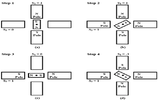
Now consider Fig 5. Let Winding A be energized and the induced magnetic poles are as the Fig 5 (a) present (we will denote the switching condition as S1=1). The other winding B is not energized. As a result the moving permanent magnet will align itself along the axis of the stator poles as shown in Fig 5 (a). In the next step, both the windings A and B are excited simultaneously, and the polarities of the stator poles are
page5 as shown in Fig 5 (b). We shall denote S2=1, for this switching arrangement for winding B. The rotor magnet will now rotate by an angle of 45o and align itself with the resultant magnetic field produced. In the next step, if we now make S1=0 (thereby de-energizing winding A), the rotor will rotate further clockwise by 45o and align itself along winding B, as shown in Fig 5 (c). In this way if we keep on changing the switching sequence, the rotor will keep on rotating by 45o in each step in the clockwise direction. The switching sequences for the switches Q1 to Q8 for first four steps are tabulated in Table 1. [9]
Figure I.5 stepping sequence (half-stepping) for a two-phase two-pole PM step motor for clockwise rotation. [26]
Table I.1:Switching sequence corresponding to the movement as shown in Fig 5.
Step 1 Step2 Step3 Step4
Q1-Q2 ON (S1=1) ON (S1=1) Q3-Q4 ON (S1=-1) Q5-Q6 Q7-Q8 ON (S2=1) ON (S2=1) ON (S2=1) It is apparent from Table 1 and Fig 5 that for this type of switching the step angle is 45o and it takes 8 steps to complete a complete revolution. So we have 8 steps / revolution. It can also be seen from Table 1 that a pair of switch (say Q7-Q8) remains closed during consecutive three steps of rotation and there is an overlap at every alternate step where
page6 both the two windings are energised. This arrangement for controlling the step motor movement is known as half stepping. The direction of rotation can be reversed by changing the order of the switching sequence. It is also possible to have an excitation arrangement where each phase is excited one at a time and there is no overlapping where both the phases are energised simultaneously, though it is not possible for the configuration has been shown in Fig.1, since that will require the rotor to rotate by 90o in each step and in the process, may inadventedly get locked in the previous position. But full stepping is achievable for other cases, as for example for the two-phase six-pole permanent magnet stepper motor as shown in Fig 6 in this case, the stator pitch θs =900
and the rotor pitch θr =600, the full step angle is given by θfs
= θ
s– θ
r=30
0 and the halfstep angle θhs
= (θ
s– θ
r)/2 =15
0 .The desired direction of rotation can be achieved bychoosing the sequence of switching. [9]
Figure I.6: Two-phase six-pole permanent magnet stop motor.[26]
The advantage of a permanent magnet step motor is that it has a holding torque. This means that due to the presence of permanent magnet the rotor will lock itself along the stator pole even when the excitation coils are de-energized. But the major disadvantage is that the direction of current for each winding needs to be reversed. This requires more number of transistor switches that may make the driving circuit unwieldy. This disadvantage can be overcome with a variable reluctance type step motor. Another way of reducing the number of switches is to use unipolar winding. In unipolar winding, there are two windings per pole, out of which only one is excited at a time. The windings in a pole are wound in opposite direction, thus either N-pole or S-pole, depending on which one is excited [10].
page7
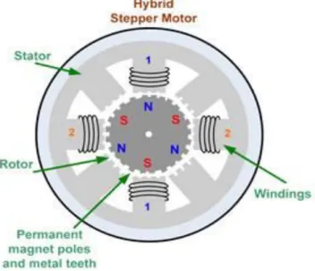
I.4.3 Hybrid Stepper Motor:
Hybrid motors share the operating principles of both permanent magnet and variable reluctance stepping motors. The rotor for a hybrid stepping motor is multi toothed, like the variable reluctance motor, and contains an axially magnetized concentric magnet around its shaft (see Figure 5). The teeth on the rotor provide a path which helps guide the magnetic flux to preferred locations in the air gap. The magnetic concentric magnet increases the detent, holding and dynamic torque characteristics of the motor when compared with both the variable reluctance and permanent magnet types. The important feature of the HSM is its rotor structure. A cylindrical or disk-shaped magnet lies in the rotor core. Stator and rotor end-caps are toothed. The coil in pole 1 and pole 3 is connected in series consisting of phase A and poles 2 and 4 are for phase B. If stator phase A is excited pole 1 acquires north polarity while pole 2 acquires south polarity. Pole 1 attracts the rotor's South Pole while pole 3 aligns with the rotor's North Pole. [11]
Figure I.4: Cross-section of HSM.
page8 When the excitation is shifted from phase A to phase B, in which case the stator pole 2 becomes north pole and stator pole 4 becomes south pole, it would cause the rotor to turn 900 in the clockwise direction. Again phase A is excited with pole 1 as south pole and pole 3 as north pole causing the rotor to move 900 in the clockwise direction. If excitation is removed from phase A and phase B is excited, then pole 2 produces south pole and pole 4 produces north pole resulting in rotor movement of 900 in the clockwise direction. A complete cycle of excitation for the HSM consists of four states and produces four steps of rotor movement. The excitation state is the same before and after these four steps and hence the alignment of stator/rotor teeth occurs under the same stator poles as explained by Kenjo (1984). The step length for a HSM and angle through which the rotor moves for each step pulse is known as step angle and is calculated by: [12][13]
Step length = 90
o/Nr (1.1) Step angle is calculated using the formula
𝜃 = 360
𝑚 ∗𝑁𝑟 or 𝜃 =
360∗(𝑁𝑠−𝑁𝑟)
𝑚 ∗𝑁𝑟 (1.2)
Where
𝜃 - Step angle in degrees
Ns- Number of stator teeth
Nr- Number of rotor teeth
m- Number of phases
Mechanical angle represents the step angle of the step. In the full step mode of a 1.8° motor, the mechanical angle is 1.8°. In the 10 micro step mode of a 1.8° motor, the mechanical angle is 0.18º. An electrical angle is defined as 360° divided by the number of mechanical phases and the number of micro step. In the full step mode of a 1.8° motor, the electrical angle is 90°. In the 10 micro step excitation of a 1.8° motor, the
page9 electrical angle is 9º. HSM material properties for each part and standard step angle of HSM are tabulated in Table 1.1 and Table 1.2 respectively. [14]
Table I.2 Material properties of HSM
S. No Motor Part Material
1. Shaft Non-Magnetic materal
2. Magnet Neodymuim Iron Boron(NdFe)/Samarium Cobalt(SMCO5)
3. Rotor core Steel sheet 4. Stator core Steel sheet
5. Coil Copper
After all this comparison it's obviously that the Hybrid stepper Motor is the motor of choice where you looking for precision position.
I.4.3.1
Unipolar HSM:
Unipolar drivers, always energize the phases in the same way. One lead, the "common" lead, will always be negative. The other lead will always be positive. Unipolar drivers can be implemented with simple transistor circuitry. The disadvantage is that there is less available torque because only half of the coils can be energized at a time.
I.4.3.2
BipolarHSM:
Bipolar drivers use H-bridge circuit try to actually reverse the current flow through the phases. By energizing the phases with alternating the polarity, all the coils can be put to work turning the motor.
A two phase bipolar motor has 2 groups of coils. A 4 phase unipolar motor has 4. A 2-phase bipolar motor will have 4 wires - 2 for each 2-phase. Some motors come with flexible wiring that allows you to run the motor as either bipolar or unipolar [5].
I.5 Control of Stepper Motors:
In many cases step motors are used for accurate positioning of tools and devices. Precision control over the rotation of the motor is required for these cases. Control of step motors can be achieved in two ways: open loop and closed loop. The open loop control is simpler and more widely used, such a scheme is shown schematically in Fig 6. The command to the pulse generator sets the number of steps for rotation and
page10 direction of rotation. The pulse generator correspondingly generates a train of pulse. The Translator is a simple logical device and distributes the position pulse train to the different phases. The amplifier block amplifies this signal and drives current in the corresponding winding. The direction of rotation can also be reversed by sending a direction pulse train to the translator. After reversing a directional pulse the stepper motor reverses the direction of rotation.
Figure I.6: Open loop control of a stepper motor.
The major disadvantage of the open loop scheme is that in case of a missed pulse, there is no way to detect it and correct the switching sequence. A missed pulse may be due to malfunctioning of the driver circuit or the pulse generator. This may give rise to erratic behavior of the rotor. In this sequel the closed loop arrangement has the advantage over open loop control, since it does not allow any pulse to be missed and a pulse is send to the driving circuit after making sure that the motor has rotated in the proper direction by the earlier pulse sent. In order to implement this, we need a feedback mechanism that will detect the rotation in every step and send the information back to the controller. Such an arrangement in Fig 7 presents. The incremental encoder here is a digital transducer used for measuring the angular displacement [15], [16].
Figure I.7: Feedback control of a stepper motor.
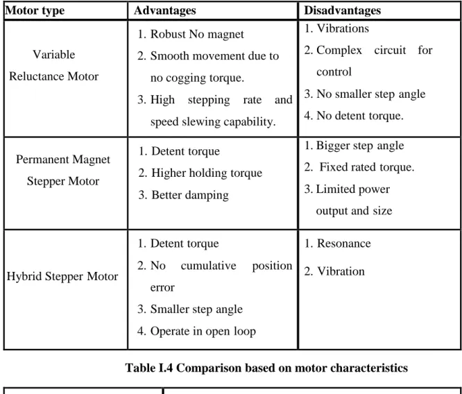
I.6 Comparison of Stepper Motor Types:
page11 stepper motor depends on torque requirements, step angle and control technique. [5] The complexity of the controller circuits are explained detail by Athani (2005). Comparisons based on motor advantages and disadvantages, motor characteristics and different phases are tabulated in Tables (1.3 - 1.5). [17]
Table I.3 Comparison based on motor advantages and disadvantages Motor type Advantages Disadvantages
Variable Reluctance Motor
1. Robust No magnet 2. Smooth movement due to
no cogging torque.
3. High stepping rate and speed slewing capability.
1. Vibrations
2. Complex circuit for control
3. No smaller step angle 4. No detent torque.
Permanent Magnet Stepper Motor
1. Detent torque
2. Higher holding torque 3. Better damping
1. Bigger step angle 2. Fixed rated torque. 3. Limited power
output and size
Hybrid Stepper Motor
1. Detent torque
2. No cumulative position error
3. Smaller step angle 4. Operate in open loop
1. Resonance 2. Vibration
Table I.4 Comparison based on motor characteristics Specifications
Motor types
VRM PMSM HSM
Step angle 0.66 º 30º 3.75 º 45º 0.45º 5º
Phases 3,4,5 2,4 2,5
Drive type Unipolar Unipolar/Bipolar Bipolar
page12
Table I.5 Comparison based on different phase properties. [18] Type of Phases Properties
2 phase
1. Simple driver circuit with low heat dissipation. 2. Less step error compared to other phases.
3. Higher accuracy due to more number of stator Poles.
3 phase
1. Torque ripple is more. 2. Poor peak torque ratio. 3. Power transistors are less.
4 phase 1. Low torque ripple. 2. Good peak torque ratio.
5 phase 1. Lower torque ripple. 2. More expensive controller.
The increased number of phases requires complicated control circuits, which provide better dynamics and considerable increase in the number of steps.
I.7 Selection of Motor:
Stepper motor can be selected based on the following specifications:
I.7.1 Electrical specifications include number of phases, step angle, winding voltage,
winding resistance , inductance, holding torque, pull-out torque, maximum slew rate, positional accuracy, temperature rise and power supply & drive circuits.
I.7.2 Mechanical specifications includes shaft length & shape, motor length, shape of
flange face, lead wire length and connector type [18].
I.8 Characteristics of stepper motor:
The construction features between the various types of SM are different, but their behaviors are similar. Some additional characteristic details about HSM are given below:
I.8.1 Static Characteristics: [17] I.8.1.1 Torque Angle Curve:
The torque increases, almost sinusoidal with angle from equilibrium position as the figure 8 shows. S is the step angle (deg) and M is the maximum angle.
page13
Figure I.8: Torque- angle curve of stepper motor.
I.8.1.2 Holding Torque (TH):
It is the maximum load torque which the energized stepper motor can withstand without slip from position.
I.8.1.3 Detent Torque (TD):
It is the maximum load torque which an un energized stepper motor can withstand without slipping and is also known as cogging torque. It is due to residual magnetism and about 5-10% of holding torque. Detent torque is typically fourth harmonic torque as figure 9 shows:
Figure I.9: Torque and detent torque profiles of stepper motor.
I.8.2 Dynamic Characteristics:
Torque versus speed relationship of a stepper motor has been shown in Figure 10. The
two curves are the in torque and the out torque curve and intermediately pull-out region is called the slewing curve .
page14 The pull-out torque versus speed curve represents the maximum friction-torque load that a stepping motor can drive before losing synchronism at a specified stepping rate with the magnetic field and motor stall. The pull-in torque versus speed curve represents the maximum frictional load at which the stepper motor can start without failure of motion when a pulse train of the corresponding frequency is applied. The pull-in torque depends on the inertia of the load connected to the motor. The pull-in region is defined as the maximum control frequency at which the unloaded motor can start and stop without losing steps. The pull-out region is defined as the maximum frequency at which the unloaded motor can run without losing steps and is alternatively called the maximum pull-out rate. [17]
I.9 Different Modes of Excitation:
Different types of excitation schemes of the stepper motor are explained by Kenjo (1984), they are:
Full step Half step Micro step
I.9.1
Full-Step:
The stepper motor uses a four-step switching sequence, which is called a full-step switching sequence which is already described above. [18]
I.9.2
Half-Step:
Another switching sequence for the stepper motor is called an eight-step or half-step sequence. The switching diagram for the half-step sequence is presenting in Fig 1.11. The main feature of this switching sequence is that you can double the resolution of the stepper motor by causing the rotor to move half the distance it does when the full-step switching sequence is used. This means that a 200-step motor, which has a resolution of 1.8°, will have a resolution of 400 steps and 0.9°. The half-step switching sequence requires a special stepper motor controller, but it can be used with a standard hybrid motor. The way the controller gets the motor to reach the half-step is to energize both phases at the same time with equal current.
page15 Figure I.11: The switching sequence for the eight-step input (half-step mode). In this sequence the first step has SW1 is on, and SW2, SW3 and SW4 are off. The sequence for the first step is the same as the full-step sequence. The second step has SW1 and SW2 are on and all of the remaining switches are off. This configuration of switches causes the rotor to move an additional half-step because it is acted upon by two equal magnetic forces and the rotor turns to the equilibrium position which is half a step angle. The third step has SW2 is on, and SW1, SW4 and SW3 are off, which is the same as step 2 of the full- step sequence. The sequence continues for eight steps and then repeats. The main difference between this sequence and the full-step sequence is that the energizing sequence for half step is A AB B BC C CD D DA. [18]
Figure1.12: Differences in the control modes for stepper motors (left: full step, right: half step). [29]
page16
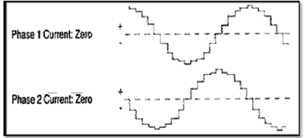
I.9.3 Micro Step Mode:
The full-step and half-step motors tend to be slightly jerky in their operation as the motor moves from step to step. The amount of resolution is also limited by the number of physical poles that the rotor can have. The amount of resolution (number of steps) can be increased by manipulating the current that the controller sends to the motor during each step. The current can be adjusted so that it looks similar to a sine wave. Figure 13 shows the waveform for the current to each phase. From this diagram you can see that the current sent to each of the four sets of windings is timed so that there is always a phase difference with each other. The fact that the current to each individual phase increases and decreases like a sine wave and that is always out of time with the other phase will allow the rotor to reach hundreds of intermediate steps. In fact it is possible for the controller to reach as many as 500 micro steps for a full-step sequence, which will provide 100,000 steps for each revolution.[19]
FIgureI.13: Phase-current diagram for a stepper motor controller in micro step mode
I.10 Type of Driver:
The basic function of a motor driver is to provide the rated current to the motor windings in the shortest possible time. Driver voltage plays a large part in a step motor’s performance. Higher voltage forces current into the motor windings faster, helping to maintain high speed torque. The main function of the driver circuit is to change the current and flux direction in the phase windings. Driving a controllable amount of current through the windings and thereby enabling maintains of short current rise and fall time is good for high speed performance. The direction change is done by changing the current direction, and this may be done in two different ways using a unipolar or a bipolar drive as explained by Acarnely (2002). [19]
page17
I.10.1 Unipolar Driver:
Winding has three leads each at the end and one in the middle. Half of the winding only is used in motor operation at any instant of time. To change the direction of rotation, end leads are chosen and the current flows in the same direction. copper volume of winding and therefore incurs twice the loss of a bipolar drive at the same output power. Unipolar winding driver circuit is simple as shown in Figure 1.14, [20].
Figure 1.14: Unipolar winding.[30]
I.10.2 Bipolar Drive
In bipolar winding current flows in both directions as shown in Figure I.15. Unipolar winding can be configured into bipolar if the centre lead is ignored. Bipolar drives are most widely used drives for industrial applications. Although they are typically more expensive to design, they offer high performance and high efficiency.[20]
The bipolar drive method requires one winding per phase. The motor winding is fully energized by turning on one set (top and bottom) of the switching transistors. Comparison between different drivers is tabulated in Table 1.6.
page18
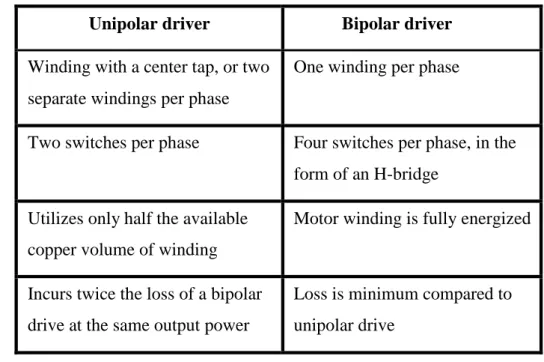
I.11 Comparison Between Drivers
:
Table I.6 Comparison between drivers Unipolar driver Bipolar driver
Winding with a center tap, or two separate windings per phase
One winding per phase
Two switches per phase Four switches per phase, in the form of an H-bridge
Utilizes only half the available copper volume of winding
Motor winding is fully energized
Incurs twice the loss of a bipolar drive at the same output power
Loss is minimum compared to unipolar drive
I.12 Stepper Motor Applications:
Stepper motors are used in a wide variety of applications in industry, including computer peripherals, business machines, motion control, and robotics, which are included in process control and machine tool applications. A complete list of applications is shown below:
I.12.1 Industrial Machines: stepper motors are used in automotive gauges and
machine tooling automated production equipments.
I.12.2 Security: new surveillance products for the security industry.
I.12.3 Medical: stepper motor are used inside scanners, samplers, and also found inside
digital dental photography, fluid pumps, respirators and blood analysis machinery.
I.12.4 Consumer Electronics: stepper motor in cameras for automatic digital camera
focus and zoom functions.
I.12.5 Robotics: stepper motors are used in making robots for angular motion. Stepper
motors are also used in business machines applications, computer peripherals applications, ect. [21]
I.13 Advantages of Stepper Motors Compared with other Motors:
In contrast to other motors stepper motors have a high holding torque even at low speed, and even on standstill. Another advantage is the simple control of stepper motors:
page19 alternate energizing of the individual coils causes the motor to move step by step. The fixed number of steps per revolution always enables the current position to be determined if the steps are counted and the motor is operated within its performance limits. No encoder is required for simple positioning tasks within the performance limits. Stepper motors are therefore ideally suited as cost-effective solutions for simple positioning tasks. [22]
I.14 Disadvantages of Stepper Motor:
Resonances can occur if not properly controlled.
Not easy to operate at extremely high speeds [23].
I.15 Conclusion
This chapter gives a profound idea about the types of the stepper motor, its principal, its construction and theses advantages and disadvantages. In the next chapter, we will present the mathematical model and the simulation results of the hybrid stepper motor.
CHAPTER II:
Modeling and
Simulation of the
Hybrid Stepper
Motor
Page 20
II.1 Introduction:
To test the dynamic response of the hybrid stepper motor (HSM), a mathematical model must be used. In addition, this model consists of electrical and mechanical equations. A mathematical model is a description of a system using mathematical concepts and language. Mathematical models are used not only in the research and engineering disciplines, but also in the curriculum of social sciences. A model may help to explain a system in a better way to investigate the effects of different components and to make predictions about behavior. In this chapter, the model of the hybrid stepper motor is presented, the simulation results will be exposing and investigations with comparison among different kind of excitations will be made. [3] [5]
II.2 Explain Some Important Meaning:
Before all of that, it is important to define some technical means such as:
II.2.1 Simulation
A simulation is a representation of something, not real. At times you might perform a simulation as practice for real life, such as a flight simulation that’s used to train pilots. The word can also be used, often dismissively, to describe something that is a fake, like a simulation of excitement or the simulation of a perfect diamond. The simulation of the hybrid stepper motor in this chapter is achieved by MATLAB-SIMULIN. [6]
II.2.2 MATLAB-SIMULINK:
The name MATLAB stands for matrix laboratory. MATLAB was originally written to provide easy access to matrix Software developed by the LINPACK and EISPACK projects. MATLAB is a high-performance language for technical computing. It integrates computation, visualization, and programming in an easy-to use environment where problems and solutions are expressed in familiar mathematical notation. Typical uses include:
1- Math and computation
2- Modeling, simulation and prototyping. 3- Data analysis, exploration, and visualization 4- Scientific and engineering graphics
Page 21 MATLAB features a family of add-on application specific solutions called toolboxes. Very important to most users of MATLAB, toolboxes allow you to learn and apply specialized technology. Toolboxes are comprehensive collections of MATLAB functions (M-files) that extend the MATLAB environment to solve particular classes of problems. Areas in which toolboxes are available include signal processing, control systems, neural networks, fuzzy logic, wavelets, simulation, and many others.[7]
Simulink, developed by the MathWorks which is a commercial tool for modeling, Simulink is an environment for simulation and model-based design for dynamic and embedded systems simulating and analyzing dynamic systems. Its primary interface is a graphical block diagramming tool and a customizable set of block libraries. It offers tight integration with the rest of the MATLAB environment and can either drive MATLAB or be scripted from it. Simulink is widely used in control theory and digital signal processing for simulation and design. This training will give you the basic knowledge of Simulink and how you can use it together with MATLAB.[8]
II.2.3 Mathematical Model:
Dynamic models typically are represented with difference equations or differential equations. Mathematical models are usually composed of variables, which are abstractions of quantities of interest in the described systems, and operators that act on these variables can be algebraic operators, functions, differential operators etc. If all the operators in a model exhibit linearity, the resulting mathematical model is defined as linear. It is also defined as an abstract and simplified of a system which specifies:
- Importance components
- Assumptions/approximations about how the system works Not an exact re-creation of the original system!
II.2.4 Modeling:
Modeling is about building representations of things in the ‘real world’ and allowing ideas to be investigated, it is central to all activities in the process for building or creating an artifact of some form or other. In effect, a model is a way of expressing a particular view of an identifiable system of some kind. Models are:
Page 22
An aid to communication between those involved in the project, especially between the requirements analyst (a development role) and the user, as part of some deliverable, And component of the methods used in development activities such as the analysis of the requirements for an artifact and the design of the artifact.
A model is an abstraction, which allows people to concentrate on the essentials of a (complex) problem by keeping out non-essential details. [9]
II.2.5 Pulse:
Pulse generators are items of electronic test equipment that are used to generate pulses normally rectangular pulses. These pulse generators are used for a wide variety of applications, but most commonly as bench test equipment when developing logic circuits of various forms. The pulse generators can be used to generate pulses that can stimulate logic circuit. In order to be able to provide the right kinds of pulses a considerable degree of adjustment is required for the pulses in terms of length, delay, repetition rate and the like. Many of the functions of a pulse generator are similar to those of a function generator or arbitrary waveform generator. As a result, many function or arbitrary waveform generators include function generator capabilities, making them multi-purpose test instruments. [1]
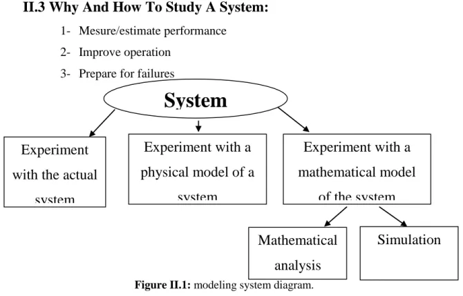
II.3 Why And How To Study A System:
1- Mesure/estimate performance 2- Improve operation
3- Prepare for failures
Figure II.1: modeling system diagram.
System
Experiment
with the actual
system
Mathematical
analysis
Simulation
Experiment with a
physical model of a
system
Experiment with a
mathematical model
of the system
Page 23
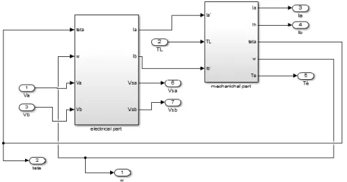
II.4 Dynamic Model of Hybrid Stepper Motors:
The hybrid stepper motor in SIMULINK consisted of two sections: electrical part and mechanical part. The electrical section is represented by equivalent circuit, configuration of which depends on the motor type. The various stepper motor is available for research. In hybrid stepper motor have permanent magnet in rotor which is toothed magnetic structure and stator have also same structure, so permanent-magnet torque can be generated in rotor and reluctance torque in stator. The rotor of hybrid motor is composed with two semi rotors, which have opposite magnetic polarity and 180-degree phase displacement in teeth position. Heretically, the motor can considered as a multi pole synchronous motor. Mathematical model of hybrid stepper motor is to study the dynamic behavior of motor. Model consists of electrical dynamic of stator together with the shaft mechanical dynamics. Electric response is much faster than the mechanical response, which allowed considering mathematical model only. Consider the mathematical model which is electrical and mechanical equations. [2][10][11][12]
FigII.2 the equivalent circuit of a two phase stepping motor.
II.4.1 Mathematical model of HSM:
The electrical equations are given by: [13]
L r KmW Ria Va dtdia sin
(II.1)
L r KmW Rib vb dtdib cos
(II.2)
Page 24 The mechanical equations are given by:
The electromechanically equation can be represented as:
After passing from the dynamical equation to the transfer function we got:
The relationship between electrical and mechanical of rotor of the motor is given by:
Where, Ia and Ib are the currents in phases A and B respectively (Amp), Va and Vb are the voltages on phases A and B respectively (Volt), ω is the rotor speed (rad/sec), θ is rotor position (rad), R is the resistance of the phase winding (Ω), L is the self-inductance of the phase winding (H). Km is the motor torque constant (Nm/A), B is the viscous friction (Nms2/rad), J is the rotor inertia (Kg.m2). TL is the load torque (Nm). The detent torque is due to permanent magnet interacting with the magnetic material of stator pole. It is negligible, as its magnitude is less than holding torque. With respect to load Variation of J and B were negligible.
J r Kd L r b Km dtd -Km a*sin r *cos *sin 4
(II.3)
(II.11)
dt d(II.4)
.sin
) cos . (Ib Ia Km Te (II.5)
L r KmW RIa VaPIa sin
(II.6)
L r KmW RIb VbPIb sin
(II.7)
J r Kd L r b KmPw -Km a*sin r *cos *sin 4
(II.8)
(II.11)
P(II.9)
er*m(II.10)
Page 25
II.4.2 Assumptions:
The mathematical model is derived based on the following assumptions as explained by Kenjo (1984)
1. Mutual inductance is neglected as being dominated by the self Inductance.
2. Variation of self inductance with the mechanical angle is assumed to be sinusoidal around the mean value.
3. Fluxes due to permanent magnet are sinusoidal with the same periodicity of the reluctance flux.
4. Detent torque is assumed to be negligible compared to magnitude of holding torque.
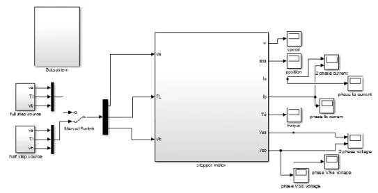
II.4.3 Stepper Motor Design In MATLAB-SIMULINK:
Fig.2 shows how to drive the stepper motor by delivering current in phases according to the mode of excitation and as per requirement of position and resolution. Mainly three type of excitation mode is defined through which motor was operated. Full step wave drive having any of the one phases is on at a time or in other words current passing only through one phase at a time. Full step two phase on have excitation achieved in the half step source which deliver at a time two phase on and current passing through both the winding. Half step excitation mode involves alternating single and dual phase operation and provides twice the resolution than full step mode, which increased smoothness at low speed.
The stepper motor model in MATLAB-SIMULINK is designed as:
Page 26 Where it contains tow essential part:
Figure II.4: subsystem contains.
The electrical part designed as:
Figure II.5: electrical part.
And the mechanical part designed as:
Page 27 Where the hybrid stepper motor parameter is given in the table below:
Motor Parameters Value
Winding Inductance L 0.04mH
Winding Resistance R 36 Ω
Number of rotor teeth, Nr 100
Torque constant Km 0.18166Nm/A
The coefficient of viscous friction B 0.0014N.m.s/rad
The detent torque Kd 1e-9[Nm]
Inertia constant J 1.1e-6kgm2
Table II.1: hybrid stepper motor (HSM) parameter.
II.5 Excitation Mode:
There are actually three types of mode excitation, this chapter is a studding for two types which given as under:
II.5.1 Full Stepping Mode:
In this mode the duty cycle of the pulse is 25%, according to the pulse require torque is generated and the current is passing through the winding as per the pattern of mode, after the calculating the frequency define time period for the pulse rate on with motor can operate.Time period for full step mode is calculated by:
Calculated T is only for 1 pulse, here two phase motor is use so it has for windings so the total time is 4T. [14]
II.5.2 Half Stepping Mode:
In half stepping mode duty cycle of pulse is 37.5% and the resolution of motor is double than the full stepping mode and even the Time period for switching the current in the phase is half than the full stepping mode. At a same time 2 phase excite with current passing through it so motor rotate in the resultant direction of the both forces witch act by the both phase. [15]
II.5.3 Voltage Source:
The source of voltage applied on the tow phase is given as:
0.3rmp
(II.11)
Page 28
Figure II.7: impulse generator.
The pulse generator delivered as:
Figure II.8: full step sequence of voltage.
Fig.8 shows the voltage delivered to the hybrid stepper motor according to full step excitation mode and as per requirement of position and resolution. There are actually three types of excitation mode is defined through which motor was operated. Full step wave drive having any of the one phase is on at a time or in other words current passing only through one phase at a time.Fig14 shows the drive voltage waveforms. Full step two phase on have excitation shown in Fig.8 which shows that at a time two phase on and current passing through both the winding.
Page 29
Figure II.9: Half step sequence of voltage.
Half step excitation mode involves alternating single and dual phase operation and provides twice the resolution than full step mode as it is shown on Fig.9, which increased smoothness at low speed. The voltage given to the stepper motor is the same voltage delivered from the driver which is depends on torque requirement for desire speed. [15]
II.6
Simulation Results:
The simulation results have been shown for 2s.Two sinusoidal inputs phase shifted according to the mode of excitation is given as input to the stepper. The pulses are given to the hybrid stepper motor. Overall simulation diagram of full and half stepping operation of hybrid stepper motor are shown in Fig 9 and Fig 10. Each phase is connected to a 24V DC voltage source. Fig 9 and Fig 10 shows the voltage waveforms of the two phases respectively.Simulation of hybrid stepper motor transient performance characteristics under no-load. Speed, position, torque and current waveforms are given in Figures bellow.
II.6.1 Full Stepping Mode:
Page 30
Figure II.11: speed and position wave form.
Figure II.12: detail speed and position wave form.
Page 31
Figure II.14: detail tow phase voltage V(A),V(b).
II.6.2 Discussions:
Fig.10 shows the performance of the motor with full stepping mode, it allow us take a look about the tow phase current wave form which increase to 0.8 [A] then decrease up to -0.8[A] (mean=0A), each phase shifted by 900 with a sine wave form and it takes a 0.04 [s] to finish one wave. Fig.11 shows the speed and position wave form of the stepper motor which increase to 24 [rad/s], it present overtake and the position to 6.2 [rad] in linear form, every step repeat after 0.01[s]. The speed of the motor is oscillatory because the change of step is very fate, there are also a little lateness it takes to move which takes 0.01 s. Fig.13 shows the performance of the motor torque is same as the speed wave form in fig.11 but with different value, it delivers a 0.05[N.m].Fig.14 shows the voltage wave form given the motor with a maximum value equal to 24[V] it present a quadrate wave form, each phase shifted by 900. The period time equal to 0.04[s] with frequency equal to 50 [HZ].This motor gives good performance with this kind of mode step.
II.6.3 Half Stepping Mode:
Page 32
Figure II.16: Speed and rotor position wave form.
Figure II.17: detail speed and rotor position wave form with half step mode.
Page 33
Figure II.19: two phase voltage wave form using half step mode.
II.6.4 Discussions:
Fig.15 shows the same wave form of current with full stepping mode and with the same value but the two phases is not shifted by 900 in that case it is actually shifted by 66.60 and the wave became a little latte.Fig.16 shows the same speed and position wave form but Slowest with half step mode in which it turned with 15 [rad/s], however it moves twice then using the full step mode in the same period, it represent also overtake equal to 15 [rad/s], the position remain to 6.2 [rad] in linear form, every step repeat after 0.005[s]. The speed of the motor is oscillatory because the change of step is fast. Fig.18 that the motor torque shortage to 0.04[N.m], the motor need to product the torque twice in the same period because of the change of the step.Fig.19 shows the voltage wave form given the motor using the half step mode with a maximum value equal to 24[V] it present a quadrate wave form either, but each phase is not shifted by 900 it is shifted actually by 66.60 The period time equal to 0.04[s] with frequency equal to 50 [HZ].
II.7 Comparison:
II.7.1 Current:
Extending to the simulation results the wave forms doesn't really matched with all different kind of excitation modes, however from the simulation results that have been investigated it can be seen that:
Page 34 It can be seen that the two phases current wave forms complete each other, in other word when the phase current in phase A is about to stop the phase B wave is applied in face that it looked simulated and shows one wave combined. The maximum current value is 0.8 [A]
II.7.1.2 Using Half Step Mode:
when the current passing through the phase A is steal applied the current in phase B is already applied too, in other word the current in phase B applied even when the current passing through the face A is steal applied with the same period and the same frequency, the two phases complete each other but the phase B start even when the current passing through the phase A not actually stopped. There is no different in the current value.
II.7.2 Speed And Position:
the simulation results shows the different of the wave forms extending to the excitation mode, according to the speed and position wave forms it can be seen that:
II.7.2.1 Using Full Step Mode: II.7.2.1.1 Speed:
the rotor does not start moving immediately it takes actually 0.01s before it accelerate then it present a linear wave form with an overshoot equal to 24[rad/s] then it start getting steady to 0 rad/s, the wave form represented for 0.01s also in meaning that every step takes a 0.01s.
II.7.2.1.2 Position:
the same Remarque that is can be seen with the position the rotor doesn't steppes
immediately it takes also 0.01s to start moving it represent a linear wave form and steady, every step takes also 0.01s, for 2s the rotor moves for 6.2 [rad]
II.7.2.2 Using Half Step Mode: II.7.2.2.1 Speed:
The wave form matched with only one thing which is it takes a 0.01s to move, after it moves and for the same period in case full stepping mode, it moves twice then using the full stepping mode in other meaning it accelerate with the same period twice, and
Page 35 that because of the half stepping mode generate two pulse in the same period, it means in the half of the first acceleration it accelerate again. There is also a change in the speed level in which it decreased to 15 [rad/s].
II.7.2.2.2 Position:
Even with position wave form it share only one thing with the two different excitation modes which is it takes 0.01s to start moving then it moves twice in half step mode then the full step mode for the same period t=0.01s. It can be notice that in the half of the period it moves again. For 2s the rotor moves for 6.2 [rad] either.
II.7.3 Torque:
Even with couple wave form it shared the same lateness for 0.01s, however let's see the different between the two wave forms according to the mode of excitations, from the simulations results it can be seen:
II.7.3.1 Using Full Step Mode:
The torque wave form have the same speed wave form but with different value equal to 0.05 N.m, it takes 0.01s for each step it present a linear wave form start with a overshoot equal to 0.05 N.m then it steady to zero.
II.7.3.2 Using Full Step Mode:
it can be notice that the torque wave form using that kind of stepping mode is matched with the speed wave form with different value in which it decrease to 0.04N.m and the motor provide the torque twice then using the full stepping mode in the same period and it shows a linear wave form and steady again. Each step takes 0.005s which mean for 0.01s it provide torque twice. It can be notice that the motor provided a good speed at low torque.
II.7.4 Voltage:
The two phase voltage wave forms is taken from the voltage delivered to the two
winding which is equal to 24V, it depends of the excitation mode applied crossing the two winding, the different between the two waves can be seen as:
II.7.4.1 Using Full Step Mode:
Page 36
II.7.4.2 Using Half Step Mode:
The two phases is shifted by 66.60 presenting a rectangle wave form for a period T=0.4s.wail the phase A is steal applied another pulse will be generated on the phase B at 66.60.
II.8 Conclusion:
In this chapter, the stepper motor model is presented. The motor can be operated in two different stepping modes namely full-step and half-step. The modeling of the two phases hybrid stepper motor was implemented in MATLAB-SIMULINK. From the simulation results it can be seen that the voltage waveforms of the two phases are 900 and 66.60 displaced according to the excitation mode. Current waveforms of two phases are similar to sine and cosine waveforms.
Chapter III:
Control of the
Stepper Motor
Page 37
III.1 Introduction:
this chapter contains basics knowledge that explains how to control the stepper and every component that it is necessary to be known, a PID controller is used to control the position of the hybrid stepper motor and to enhance the performance of the open loop control for a given reference input using three modes; full step, half step, and micro step. The experimental results of these three modes are presented using Matlab/Simulink software version 13.a. In addition, a discussion and investigation has been made among the three modes.
III.2 Some Basic Definitions:
III.2.1 What is a System?
A system is a collection of components that interact with one another and with their environment. Such us Human beings, mechanical devices, an electrical switch, plants, animals, the atmosphere, the stock market, the political system, helicopters, missiles, avionics, and so on. [1]
III.2.2 Control System:
A control system is an interconnection of components forming a system configuration that will provide a desired system response. Control is used to modify the behavior of a system so it behaves in a specific desirable way over time. The basic for analysis of a system is the foundation provided by linear system, which assumes a cause effect relationship for the components of a system. A component or process to be controlled can be represented by a block as Figure1 shows. All these are being accomplished today by control methods and what automatic control systems are designed to do, without human intervention. Control is used whenever quantities such as speed, altitude, temperature, or voltage must be made to behave in some desirable way over time. There are two main types of control loops: Open loops, which operate with human input, and closed loops, which are fully autonomous. Some loops can be switched between closed and open modes. When open, a switchable loop is manually controlled and when closed it is fully automated. [2] [3] [4]
![Figure 1.3 Schematic diagram of a two-phase two-pole permanent magnet stepper motor. [26]](https://thumb-eu.123doks.com/thumbv2/123doknet/12270836.321618/21.892.326.610.521.721/figure-schematic-diagram-phase-permanent-magnet-stepper-motor.webp)
![Figure 1.15: Bipolar winding. [30]](https://thumb-eu.123doks.com/thumbv2/123doknet/12270836.321618/34.892.288.659.310.557/figure-bipolar-winding.webp)