HAL Id: hal-02534030
https://hal.archives-ouvertes.fr/hal-02534030
Submitted on 7 Apr 2020
HAL is a multi-disciplinary open access
archive for the deposit and dissemination of
sci-entific research documents, whether they are
pub-lished or not. The documents may come from
teaching and research institutions in France or
abroad, or from public or private research centers.
L’archive ouverte pluridisciplinaire HAL, est
destinée au dépôt et à la diffusion de documents
scientifiques de niveau recherche, publiés ou non,
émanant des établissements d’enseignement et de
recherche français ou étrangers, des laboratoires
publics ou privés.
Effect of Inlet Type on Shear Stress and Mixing in an
Annular Photobioreactor Involving a Swirling Decaying
Flow
Jeremy Pruvost, Jack Legrand, Patrick Legentilhomme, Arnaud Muller-Feuga
To cite this version:
Jeremy Pruvost, Jack Legrand, Patrick Legentilhomme, Arnaud Muller-Feuga. Effect of Inlet Type on
Shear Stress and Mixing in an Annular Photobioreactor Involving a Swirling Decaying Flow. Canadian
Journal of Chemical Engineering, Wiley, 2004, 82 (3), pp.495-503. �10.1002/cjce.5450820310�.
�hal-02534030�
* Author to whom correspondence may be addressed. E-mail address: jeremy.pruvvost@physique.univ-nantes.fr
I
t is well known that photosynthetic microorganisms like microalgae are nowadays of potential interest in various areas, as for example in food, cosmetics, environment or pharmaceuticals (Pulz, 2001; Richmond, 2000). To produce such organisms, particular devices called photobioreactors are employed. But the high physiological need of microalgae in light makes good growth conditions difficult to ensure in photobioreactors, especially when high concentrations of microorgan-isms are required to achieve sufficient productivity. Due to cells mutual shading, the light depth penetration can be extremely reduced, result-ing in only one part of the culture beresult-ing sufficiently illuminated. For this reason, photobioreactor efficiency is generally limited (Tsoglin and Gabel, 2000), and that explains why studies made to improve the light use in photobioreactors are of primary interest to develop efficiency of these types of processes. One key factor is hydrodynamic conditions that can have a marked influence on the efficiency of photobioreactors (Grima et al., 1999; Pulz and Scheibenbogen, 1998). The application of a three-dimensional flow-field allows the microalgae movement across the light gradient, thereby homogenizing the amount of light received per microalga and its biological use. A previous study has emphasized the advantage of swirling flows in an annular photobioreac-tor by comparing trajecphotobioreac-tories of microalgae obtained in this case with a commonly employed pseudo-axial flow (Pruvost et al., 2002a). Swirl flows reveal and generate an important radial mixing along the light gradient in addition to the main rotating motion of the flow. These results confirm the improvement observed by applying such types of flows to enhance the rate of a photochemical reaction in an annular photoreactor (Pruvost et al., 1999), especially for a high light-absorbing medium such as microalgal culture. Thus, swirling flows appear to be an interesting solution for annular photobioreactors.Except for a theoretical study dedicated to the investigation of the interest of swirling flows implementation in photobioreactors by simulating cultures of Porphyridium cruentum as a function of the hydrodynamic conditions (Pruvost et al., 2002b), only some attempts have been made to apply particular hydrodynamical conditions like swirl flows in photobioreactors in regards to literature. Carlozzi and Torzillo
Effect of Inlet Type on Shear Stress and Mixing
in an Annular Photobioreactor Involving a
Swirling Decaying Flow
Jérémy Pruvost*
1
, Jack Legrand
1
, Patrick Legentilhomme
1
, Arnaud Muller-feuga
2
1
GEPEA UMR – CNRS 6144, Faculté des sciences et techniques, 2 rue de la Houssinière, BP 92208, 44322 Nantes
Cedex 3, France.
2
PBA Laboratory, IFREMER, rue de l’Île d’Yeu, BP 21105, 44311 Nantes Cedex 3, France.
Improvement of mixing can lead to an enhance-ment of photobioreactors productivity, provided that the adverse effect of shear forces is kept below the fragility threshold of cells. Implementation of a swirling decaying flow induced by a tangential inlet in an annular photobioreactor was investigated. The study focused on a compromise solution between the mixing and the resulting shear stress, and various hydrodynamical characteristics were measured for five types of tangential inlets and three Reynolds number values. Comparison with a pseudo-axial flow induced by a radial inlet indicates that swirling flows are suitable in the particular application of microalgal cultures.
Keywords: swirling flow, annular geometry, mixing,
(1996) applied roll-cells of Dean type in strongly curved tubular photobioreactors for the culture of Spirulina platensis. Another example is found in Miller et al. (1964) with the use of Couette-Taylor vortices that appear in cylindrical annular space, one of the cylinders being rotated. Photosynthesis was found to increase with the rotor speed. But, implementation of rotating parts complicates the reactor design. In this study, other types of rotating flow patterns were thus regarded for application to photobioreactors of annular geometries.
Swirling flows generated by tangential inlets have been found to induce a three-dimensional flow-field and to improve turbulence intensities (Gupta et al., 1984; Aouabed et al., 1995). Such a device can be easily implemented in annular geometry, and despite the fact that swirling motion decays freely along the axis, they are often used in cylindrical geometries to enhance mass or heat transfer, as in hydrocy-clones or heat exchangers (Legentilhomme and Legrand, 1991). Furthermore, their effect on radial mixing suggests their application to increase the culture displacement along the light gradient in a photobioreactor, assuming that the length of the tubes is not too long compared to the swirl intensity decay.
But biological applications imply particular constraints, particularly when stress-sensitive elements such as microalgae are involved. A disturbed flow leads to higher velocity gradient values, resulting in a greater shear stress-field. A compro-mise would be to ensure sufficient mixing while keeping the shear-stress forces within an acceptable range. However, little is known about the effects of hydrodynamic stress on microalgae, mainly because of the cell fragility of microalgae, which remains difficult to investigate (Chisti, 1999; Jaouen et al., 1999). The results depend on the species cultured, which exhibit quite different types of cell fragility and various physio-logical responses, from the decrease of the growth rate to the cell destruction. Thus, a hydrodynamic study cannot establish a definitive compromise solution for all microalgae, but can improve our understanding of the processing of microalgal cultures in photobioreactors. The characterization of a large set of operating conditions obtained with different inlets can elucidate the problems relating to microalgal cultures in a swirling decaying flow.
Few studies have concerned swirling decaying flows induced by a tangential inlet. In fact, such hydrodynamics are difficult to investigate because the motion generated is three-dimensional and highly disturbed (Clayton and Morsi, 1984; Algifri et al., 1988; Farias Neto et al., 1998). A previous work showed that particle image velocimetry (PIV) can be used to measure some hydrodynamic characteristics in swirling decaying flow, such as velocity components, turbulence intensity and swirl intensity (Pruvost et al., 2000). This technique was used in the present work to study the influence of inlet conditions on swirl flow. The velocity field, initial rotating motion, streamlines and shear stress-field in the inlet of the annulus were measured, and swirl intensity and turbulence energy were determined far from the inlet to estimate the influence of injection conditions on the resulting mixing. Calculation methods are described and results presented for five kinds of tangential inlets and three Reynolds number values. The influence of the geometrical characteristics of tangential injection on the resulting flow is shown. Finally, the results are compared with those obtained for a radial inlet, which is usually employed in photobioreactors of annular type (Muller-Feuga et al., 1998). This comparison indicates that hydrodynamic conditions are improved with a
tangential inlet, which produces an effective three-dimensional motion suitable for photobioreactor application.
Experimental Set-up
The experimental set-up was made to reproduce one of the annular light chambers of a photobioreactor already described elsewhere (Muller-Feuga et al., 1998). The annular test section was composed of two concentric tubes with a total length of 1.5 m and an annular gap width of e = 30 mm. The internal radius of the outer cylinder, Ro, was 50 mm, and the outer radius of the inner tube, Ri, was 20 mm. All parts of the experi-mental device, including the annular test cell and the inlet, were in Plexiglas to provide good optical conditions for PIV measurements. To minimize optical distortion due to the curved walls and the difference in optical indexes, the annulus was enclosed within a rectangular Plexiglas box filled with water, and the inlet was machined in a cubic block.
Six inlet configurations were investigated: one circular radial inlet and five tangential inlets. As shown by Legentilhomme and Legrand (1991), swirl intensity depends on two parame-ters for a given Re value: jet velocity, which is a function of the inlet cross-section Se, and jet impingement on the wall of the inner cylinder, which reduces the initial rotating motion. Three different cross-sections were investigated, but except for the smallest one with a diameter φe equal to the annular gap width e, a jet impingement is observed with a classical circular shape of the inlet (φe > e). Thus, one means of improving inlet efficiency is to prevent impact on the inner cylinder by
changing the initial circular shape of the inlet. An alternative oblong shape is proposed here. As shown in Figure 1, this shape reduces jet impact. The geometrical characteristics φe and le of the two oblong inlets investigated were chosen to obtain the same cross-section S as corresponding inlets of circular shape (Figure 1). The complete set of inlets is described in Table 1.
To simplify the experimental investigation, inlet configura-tions were modified by using different circular injection inserts (Figure 2), which could be screwed onto the inlet transparent cubic box. The outlet of the annulus was an axial type in order not to disturb the flow. Experimental measurements were made for the three different Reynolds number values given in Table 2. The geometrical characteristics of the different inlets can be related to the Reynolds number in the annulus by defining Sno, which represents the initial swirl intensity (Legentilhomme and Legrand, 1991):
Sn Se o i 2 o2 Re= π(R ·- R ) (1)
where Se is the cross-section area of the inlet considered. This value was used to investigate inlet influence on swirling flow intensity.
PIV Investigation
A previous work has shown that PIV can be used in an annular swirling decaying flow (Pruvost et al., 2000). However, due to the decay of swirl motion along the annulus axis, the flow cannot be considered as fully developed along the test cell. Thus, the full characterization of hydrodynamic characteristics requires extensive measurements, making the comparison of the six inlets for the three Reynolds number values quite time consuming. To define the desirable compromise solution between the shear stress-field and mixing, the PIV investiga-tion was reduced to two representative geometrical aspects: – The first was chosen to define the shear stress-field and the
initial rotating motion. The chosen point was the location of the maximum of the swirl motion and of the shear stress-field, i.e. directly within a vertical plane in the inlet of the annulus, as shown in Figure 3.
Table 1. Geometrical characteristics of inlets
Type Tangential (A) Tangential (B) Tangential (C) Tangential (D) Tangential (E) Radial (F)
Shape Circular Circular Circular Oblong Oblong Circular
Cross-section S1 = 44 cm2 S
2 = 16 cm2 S3 = 7 cm2 S1 = 44 cm2 S2 = 16 cm2 S1 = 44 cm2
Geometric φe = 65 mm φe = 45 mm φe = 30 mm φe = 82 mm φe = 82 mm φe = 65 mm
characteristics le = 90 mm le = 70 mm
Figure 2. Inlet cubic block and circular fluid inlet inserts used to modify
entrance conditions (A: tangential inlet, circular shape, cross-section
S1; B: tangential inlet, circular shape, cross-section S2; C: tangential inlet, circular shape, cross-section S3; D: tangential inlet, oblong shape, cross-section S1; E: tangential inlet, oblong shape, cross-section S2; F: radial inlet, circular shape, cross-section S1).
Table 2. Hydrodynamic conditions investigated
Re 5400 3000 1800
Q (m3.h-1) 2.14 1.19 0.71
U (m.s-1) 0.09 0.05 0.03
– The second concerned the estimation of mixing parameters, such as swirl intensity and turbulent energy, related to the decay of the swirl motion. Measurements were made for a single axial position. In order to study swirl decay far from the inlet, a point was chosen at the axial coordinate
x = 1043 mm and the circumferential coordinate ξ = π/2 from the tangential inlet axis. Velocity values were thus obtained along a single radial profile, as described in Pruvost et al. (2000).
Measurements were made with the Dantec PIV 2000 system composed of a continuous laser, an optical shutter to create laser pulses, a lens to generate the laser sheet, and a CCD camera 80C42 DoubleImage 700 set perpendicularly to the laser sheet.
Calculation Methods
Mixing Parameters
Mixing was evaluated by determining the swirl intensity and the turbulent energy for given operating conditions. As described before, those values were achieved at a fixed distance far from the inlet, to reduce the measurement time. These flow characteristics were calculated using PIV data according to methods described by Pruvost et al. (2000). To achieve stable results, 200 PIV acquisitions were used to determine the mean values of the velocity vector, and 1000 for turbulent intensities. Swirl intensity, Sn, was defined as (Gupta et al., 1984): Sn uwr dr e u rdr Ri Ro Ri Ro =
∫
∫
2 2 2 (2)where u and w are the mean axial and tangential velocity components respectively, and r the radial coordinate.
Intensity of the flow turbulence was characterized by determining the following criteria:
k = (Tx2 + Tr2 + Tξ2) with T u U T U T w U x = ' · r = ' · = ' · 2 2 2 , v and ξ (3)
where u' is the instantaneous fluctuation of the axial velocity component, v’ that of the radial one, and w’ that of the circumferential one. (___) denotes time-averaging.
To allow comparison between different flow regimes and investigated Re, a global value K of the local quantity k was defined. It simply corresponds to the average of all k values obtained for a given flow condition (spatial averaging of the radial profile of k).
Inlet Measurements
To provide complete visualization of the flow within the inlet, the acquisition area was divided into two parts: the first one allowed visualization into the annulus, while the second was directly adjacent to the inlet, as shown in Figure 3. These results were then superposed to obtain the final velocity-field. An example of the resulting velocity-field is shown in Figure 3. Two hundred instantaneous PIV acquisitions were made for each acquisition area. Representations of the mean velocity-fields and the corresponding velocity magnitude showed the
features of the inlet flow set-up, especially the rotating motion created by tangential inlets around the inner cylinder. The velocity magnitude Un was described in the visualization plane by:
Un = v2·+w2·
(4)
To facilitate the comparison between entrance conditions, a global value (simply representing an average value of the circumferential component over the entire velocity-field) was deduced. This value, designated as initial rotating motion W, allows a direct comparison of the efficiency of the different inlets in creating a swirl motion in the entrance of the annular geometry.
To provide a more thorough investigation of the inlet flow-field, streamline distribution was determined from the velocity-fields. Streamlines in cylindrical coordinates were deduced from the stream function ψ(x,r,ξ) defined for a location P by:
Ψ( )P Ψ0 r v d w dr) P
= +
∫
( ξ−0 (5)
where ψo is the value of the stream function obtained at the origin O.
Streamline calculation was done according to an integrative method described by Imaichi and Ohmi (1983). The location O was set in the most stable part of the flow, in the middle of the annular gap (r = 35 mm, ξ = π), to prevent the accumula-tion of errors during iterative resoluaccumula-tion of Equaaccumula-tion (5).
Hydrodynamic shears were defined in the radial-circumfer-ential plane by the deformation tensor ε:
ε ε ε ε ε ξ ξ ξ ξ ξ ξξ (w r) 1 r r ( ) = = ∂ ∂ ∂ ∂ + ∂ ∂ ∂ ∂ + ∂ ∂ ∂ ∂ +
rr r r v r r r v r w r r v r w v r 1 2 1 2 1 1 (6)According to Equation (6), hydrodynamic stress is due to four individual deformation components, err, erξ, eξr, eξξ, each of which can be calculated using PIV measurements. To simplify the representation of the results, these values were not analyzed separately, but expressed using the following global criterion, εtot:
εtot ( = εrr· + εξξ· + 2×εrξ· ) 1
2 (7)
The differentiation scheme used to determine each individual deformation in Equation (6) was based on a central difference algorithm described by Raffel et al.(1998). This method appears to be well-adapted to experimental PIV measurements, provid-ing an expression of the velocity-field on a grid, as shown in Figure 3 where a typical example of instantaneous PIV acquisi-tion is given. For some velocity V obtained at a locaacquisi-tion O(i,j) of the grid, the differentiation is defined by:
∂ ∂ =
[
(
+ +)
−(
+ +)
]
∂ ∂ = + + + + + − + + − − − − + + + + − V r r V V V V V V V V V V i j i j i j i j i j i j i j i j i j i j i j , , , , , , , , , , , 1 8 2 2 1 8 2 1 1 1 1 1 1 1 1 1 1 1 1 1 1 ∆ ∆ ξ ξ[
(
11)
−(
1 1+2 1 + 1 1)
]
− + − − − Vi ,j Vi ,j Vi ,j (8)where i and j define grid coordinates corresponding respec-tively to the circumferential and radial directions.
Equation (8) was used to deduce the shear stress-field from PIV velocity-field measurements. To synthesize the study of the Reynolds number effect, local shear-stress values εtot obtained in the annular field were summarized as a single mean value referred to as mean shear-stress εm.
Results and Discussion
Effect of Inlet Type
The results presented first in this section concern only the intermediate Reynolds number value of 1800 in order to emphasize the influence of inlet type on the resulting flow. The influence of the Reynolds number is considered later. Figure 4 shows velocity-fields measured using PIV and the deduced velocity magnitude Un. The effects of the tangential inlet are readily apparent. The jet flow generated by the swirl inducer is more marked, creating a rotating motion around the inner cylinder. These results are of interest because they characterize the intensity of the initial rotating motion in the annulus, which decreases progressively away from the inlet. Another important feature of swirl flows is the centrifugal force due to the rotating motion, which shifts the maxima of velocity to the vicinity of the outer cylinder and decreases velocity near the inner cylinder, as it can be observed for circumferential positions ranging between ξ = 0 and ξ = π (Figure 4). These results, already observed by Pruvost et al. (2000) are consistent with the numerical prediction of Farias Neto et al. (1998) and other experimental investigations where a large decrease in circumferential velocity near the inner cylinder was observed (Gupta et al., 1984; Clayton and Morsi, 1984). This feature is characteristic of free decaying swirling flow, with a forced-vortex part close to the inner cylinder and a free-forced-vortex part in the vicinity of the outer wall. This emphasizes wall effects on the swirl intensity decrease.
The influence of the cross-section area is apparent when the velocity-fields obtained with the five tangential inlets
are compared. Conservation of the flow rate induces a more intensive rotating motion in small sections. Thus, maximum velocity-field values are obtained with the smallest cross-section S3. For cross-sections S2, the influence of the inlet shape is apparent. For a given cross-section area, the oblong shape reduces jet impact on the inner cylinder, thereby increasing the rotating motion and improving tangential inlet efficiency for a given cross-section. The same results are achieved with cross-section S1 (results not shown). Results for the radial inlet reveal the direct impingement on the inner cylinder, leading to instabilities appearing in the visualization plane.
As shown in Figure 5, streamlines provide global visualiza-tion of inlet hydrodynamics, allowing improved understanding of flow structure. As observed for velocity-fields, the radial inlet causes several flow disturbances. With tangential inlets, the swirl motion around the inner cylinder is apparent from the circular shape of streamline representations as shown for cross-section S3. Flow is however less structured for inlets exhibiting a large impact on the inner cylinder. For cross-section S1, only small perturbations of the streamlines occur with the oblong shape, whereas the circular shape generates a disturbed flow. The same conclusions are achieved with cross-section S2 (results not shown). The swirling motion in the inlet can thus be improved when oblong shapes are used.
Figure 6 shows shear stress-fields. The maximum hydrody-namic shear-stress values appear to be located at points near the walls where the disturbances previously observed on streamline representations occur, i.e. near flow impingement on the inner cylinder and where flow intercepts the tangential injection. These sites, which are schematically summarized in Figure 7, are mainly located in the circumferential area between ξ = 3π/2 and ξ = 2π. Only the tangential inlet with cross-section S3 generates high shear stress-field values (Figure 6). Other inlets exhibit nearly the same shear stress-field (same conclusion for cross-section S1, results not shown). Thus, hydrodynamic shear-stress appears to be mainly due to the intensity of swirl motion. Swirl motions of high intensity
Figure 4. Representation of velocity-fields and isovalues of velocity
increase maximum shear stress values. When these results are compared with those obtained with the radial inlet, there seem to exist two different causes for hydrodynamic shear-stress obtained with radial and tangential inlets: with the radial inlet, the impact of flow on the inner cylinder creates disturbances and thus hydrodynamic shear-stress, whereas the shear-stress induced by the tangential inlet is mainly due to rotating motion. Except for the inlet with cross-section S3, the shear stress-field within the inlet is not greatly improved through the use of a tangential swirler, despite the rotating motion generated.
Figures 8 and 9 show global parameters measured to estimate mixing far from the inlet, namely swirl intensity Sn and turbulent energy K respectively, as a function of inlet-type and Reynolds number. In terms of the results obtained with the Reynolds number value Re = 1800 studied in this section, swirl intensity data are consistent with observations made for velocity-fields and with those of Legentilhomme and Legrand (1991). Decreasing the cross-section area of the tangential inlet increases swirl intensity. Results for turbulent energy lead to the same conclusion: high turbulent energy values are obtained for inlets that generate an intensive swirl motion. By comparing this with results obtained for the radial inlet, it is quite apparent that swirling flow enhances turbulent intensi-ties in the annulus for a given Reynolds number. This is in agreement with findings in a previous study in which turbulent intensities measured in a swirling decaying flow, as compared to those of a pseudo-axial flow, showed a five-fold increase near
Figure 6. Representation of shear stress-fields εtot for Re = 1800 (εtot in s-1).
Figure 7. Schematic localization of maximum hydrodynamic
shear-stress in the inlet.
Figure 8. Results for swirl intensity measurement at x = 1043 mm.
the inlet (Pruvost et al., 2000). Other studies on swirl motion using different geometrical configurations or inlet types have also shown enhanced turbulent intensities (Aouabed et al., 1995; Clayton and Morsi, 1984). Finally, these results provide further data considering inlet shape. An oblong shape is more efficient than a circular one for cross-section S2, but provides no improvement for cross-section S1. This is explained by the disturbances generated for cross-section S1, which are marked for both shapes, that reduce the influence of inlet shape.
Influence of the Reynolds Number
The swirl intensity values in Figure 8 indicate that the influence of the inlet is enhanced by an increase of the Reynolds number. Higher swirl intensity values are obtained for the smallest cross-section S3 and oblong shapes. However, cross-section S3 does not produce much higher swirl motion values than the other inlets with larger cross-sections, despite the intensive rotating motion observed for velocity-fields in the previous section. Moreover, according to the initial rotating motion study, this is explained by inlet flow distribution, which appears to be disturbed as compared to the structured one observed when an oblong inlet with cross-section S2 is used.
The influence of the inlet on changes in turbulent energy
K decreased with Re (Figure 9). For the lowest Re value,
turbulent energy was greatly enhanced in swirling flows as compared to pseudo-axial hydrodynamics. The improvement factor ranged between 1.7 and 2.7. Two inlets appear to be particularly efficient: the oblong tangential inlets with cross-section S2 or S3. For the highest Re value, there was only a slight improvement between swirling flows and pseudo-axial hydrodynamics. The turbulent energy achieved was almost the same, regardless of the tangential inlet used.
The quantification of the initial rotating motion is in agreement with results shown in the previous section. Inlets with small cross-sections (S3 and S2) provided initial swirl motion of higher intensity (Figure 10). As previously noted in swirl intensity investigations (Figure 8), the most efficient inlet was the oblong one with cross-section S2. W-values were greater than those calculated for the tangential inlet with the smallest cross-section (S3). Although this last inlet provided higher local circumferential velocity values, as indicated in the
section dealing with velocity-field investigations, low velocity values were observed in recirculation regions (Figure 4). The oblong inlet with cross-section S2 provided more structured flow and produced more efficient swirl motion characterized by a higher value for initial rotating motion W. The differences in inlet increase in relation to the Reynolds number emphasize the influence of the geometrical characteristics of the tangen-tial inlet. For the highest Reynolds number value investigated, the initial rotating motion obtained for the oblong inlet with cross-section S2 was enhanced twofold compared to that for the circular inlet with cross-section S1. When the shape of the inlet is considered for a given cross-section, W is always greater for the oblong shape, indicating the advantage of this geometrical form.
The mean shear-stress values (Figure 11) indicate that the same conclusions as those reached in the previous section can be drawn for any of the investigated Re values. An increase in this parameter leads necessarily to higher shear-stress in the entrance. The tangential inlet with cross-section S3 and oblong inlets provided higher shear-stress values, while no significant differences were observed for other inlets. Except for the circular inlet with cross-section S3 and the oblong inlet with cross-section S2 for the highest Reynolds number, the mean shear-stress values induced by tangential inlets were no greater than those observed with a radial inlet. This can be explained by flow impingement on the inner cylinder induced by the radial inlet.
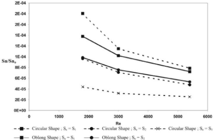
The study of the five types of tangential inlets showed that each one leads to different swirling flows, whose intensity and initial rotating motion depend on various parameters, such as injection velocity in the annulus and flow impingement on the inner cylinder. Thus, each of the tangential inlets generates a swirling flow that differs in efficiency. This efficiency was estimated by calculating the ratio between swirl intensity
Sn, measured far from the inlet, and initial swirl intensity Sno
(Equation 1).
As initial swirl intensity Sno characterizes swirl intensity only as a function of the cross-section for a given inlet or the Reynolds number in the annulus. The Sn/Sno ratio can be used to estimate the influence of inlet shape on swirl motion decay for a given cross-section. Figure 12 shows that swirl motion
decay does not appear to be dependent on inlet shape, except with cross-section S1 for which disturbances caused by flow impingement on the inner cylinder influenced the resulting swirling intensity of the flow. Thus, the use of oblong shapes is advantageous because they prevent flow impingement and produce a higher initial rotating motion (Figure 10), creating a more efficient swirl flow, which then follows the same free decay as with the circular shape (Figure 12).
When these results are considered in terms of applica-tions to microalgal cultures, swirl motion could improve light availability since turbulent energy is linked to mixing in the annulus. The use of different tangential inlets induces swirling flows of different intensity, with a greater or lesser increase in hydrodynamic stress. As the effects of hydrodynamic stress on microalgae are various and complex, only a general conclusion can be reached. It is confirmed that, whatever the tangential inlet is, a better mixing is achieved in the annular geometry with swirling decaying flows compared to a classical pseudo-axial flow, even for a position far from the inlet where the swirl motion remains effective. For the lowest Re value, hydrody-namic shear-stress is poorly dependent on the geometrical characteristics of the inlet, whereas turbulent intensities are enhanced in swirling flows. In terms of this Re value, tangential inlets generating an intensive swirl motion seem preferable. For the highest Re value, hydrodynamic shear-stress appears to be dependent on inlet configuration, as the influence on turbulent energy does not appear to be great. Inlet choice depends on the sensitivity of microalgae. If cells are stress-sensitive, tangential inlets with cross-section S1 and circular ones with cross-section S2 have to be used. In this case, signifi-cant mixing is involved, whereas hydrodynamic shear-stress is almost the same as that measured with the radial inlet.
Conclusion
This study developed a PIV characterization to determine the essential hydrodynamic features of a swirling flow, i.e. velocity-field, turbulent energy, swirl intensity, initial rotating motion, shear stress-field and streamlines. These values were compared with pseudo-axial hydrodynamics generated by a radial inlet. Five types of tangential inlets were studied, which involved
swirling flows with different characteristics. Three cross-sections were investigated, and an alternative oblong shape was substituted for the common circular one. Measurements of the velocity-field in the inlet showed that an oblong shape reduces the impact of the inlet jet on the inner cylinder of the annulus. The oblong shape provides a swirl motion of greater intensity for given Re values and cross-sections. However, determination of the resulting shear stress-field indicates that an increase in swirl motion leads to higher hydrodynamic stress values, which demonstrates the interest of this type of study for accurate characterization of hydrodynamics.
An important result concerns annular type photobioreactor design, especially when microalgae are found to be sensitive and cultures are restricted to low Re values: for the same cross-section S1, hydrodynamic shear-stress values in the inlet of the annulus are not higher for swirling flows than for the more classical pseudo-axial flow. While reducing the impact of fluid on the inner cylinder, tangential inlets with a large cross-section generate a swirling flow of low intensity, but still sufficient for enhancing turbulent energy and mixing. This promotes swirling flows suitable for microalgal cultures in annular photobioreactor geometries. The generation of three-dimensional hydrodynamics, even for low Re values, enhances the displacement of microalgae along the light gradient, thereby optimizing the light received by each microorgan-ism. Swirling flows appear to be an interesting solution to the problem of light accessibility in annular photobioreactors. However, further investigations are needed to determine the effects of such flows on biological media.
Nomenclature
e thickness of the annular gap, (m)
i grid coordinate corresponding to the circumferential direction
j grid coordinate corresponding to the radial direction
k dimensionless turbulent energy (Equation 3)
K mean value of dimensionless turbulent energy
le geometrical characteristic of inlets of oblong shape (Figure 1)
Q flow rate in the annulus, (m3/s)
r radial position with respect to the annulus axis (m)
Ri external radius of the inner cylinder, (m)
Re 2 e U / ν: Reynolds number
Ro internal radius of the outer cylinder, (m)
Se cross-section of the inlet injection, (m2) Sno initial swirl intensity (Equation 1)
Sn swirl intensity (Equation 2)
Tx axial turbulent intensity component
Tr radial turbulent intensity component Tξ circumferential turbulent intensity component
u mean axial velocity, (m/s)
u’ velocity fluctuation in the axial direction, (m/s)
U Q / (π (Ro2-Ri2)): average velocity in the annulus, (m/s) Un velocity magnitude, (m/s) (Equation 4)
v mean radial velocity, (m/s)
v’ velocity fluctuation in the radial direction, (m/s)
V generic velocity, (m/s)
w mean circumferential velocity, (m/s)
w’ velocity fluctuation in the circumferential direction, (m/s)
W initial rotating motion, (m/s)
x axial position with respect to the tangential inlet, (m)
Greek Symbols
∆ξ circumferential distance between PIV neighboring points of the velocity-field grid, (m)
∆r radial distance between PIV neighbouring points of the velocity-field grid, (m)
ε deformation tensor (Equation 5) εm mean value of shear-stress, (s-1)
εtot local value of shear-stress, (s-1) (Equation 6)
φe diameter of the tangential inlet, (m)
ν kinematic viscosity of water, (m2/s)
ξ circumferential position with respect to the tangential inlet axis (radians)
Special Symbols
¯¯ time-averaging
References
Algifri A.H., R.K. Bhardwaj and Y.V.N. Rao, “Eddy Viscosity in Decaying Swirl Flow in a Pipe”, Appl. Sci. Res. 45, 287–302 (1988).
Aouabed H., P. Legentilhomme and J. Legrand, “Wall Visualization of Swirling Decaying Flow Using a Dot-Paint Method”, Exp. Fluids 19, 43–50 (1995) .
Carlozzi P. and G. Torzillo, “Productivity of Spirulina in a Strongly Curved Outdoor Tubular Photobioreactor”, Appl. Microbiol. Biotechnol. 45 (1–2), 18–23 (1996).
Chisti Y., “Shear sensitivity” in “Encyclopaedia of Bioprocess Technology: Fermentation, Biocatalysis, and Bioseparation”, v.5, Flickinger, M.C. and Drew, S.W. editors, Wiley, New York (1999), pp. 2379–2406.
Clayton B.R. and Y.S.M. Morsi, “Determination of Principal Characteristics of Turbulent Swirling Flow Along Annuli. Part 1: Measurement of Time Mean Parameters”, Int. J. Heat Fluid Flow 5, 195–203 (1984).
Farias Neto S.R., P. Legentilhomme and J. Legrand, “Finite-Element Simulation of Laminar Swirling Decaying Flow Induced by Means of a Tangential Inlet in an Annulus”, Comp. Meth. Appl. Mech. Eng. 165, 189–213 (1998).
Grima M.E., A.F.G. Fernandez, G.F. Camacho and Y. Chisti, “Photobioreactors: Light Regime, Mass Transfer, and Scaleup”, J. Biotech. 70, 231–247 (1999).
Gupta A.K., D.G. Lilley and N. Syred, “Swirl Flows”, Abacus Press, Cambridge (1984).
Imaichi K. and K. Ohmi, “Numerical Processing of Flow-Visualization Pictures – Measurement of Two-Dimensional Vortex Flow”, J. Fluid Mech. 129, 283–311 (1983).
Jaouen P., L. Vandanjon and F. Quéméneur, “The Shear Stress of Microalgal Cell Suspensions (Tetraselmis Suecica) in Tangential Flow Filtration Systems: The Role of Pumps”, Biores. Technol. 68, 149–154 (1999).
Legentilhomme P. and J. Legrand, “The Effects of Inlet Conditions on Mass Transfer in Annular Swirling Decaying Flow”, Int. J. Heat Mass Transfer 34, 1281–1291 (1991).
Miller R.L., A.G. Fredrickson, A.H. Brown and H.M. Tsuchiya, “Hydromechanical Method to Increase Efficiency of Algal Photosynthesis”, Ind. Eng. Chem. Proc. Des. Dev. 3, 134–143
(1964).
Muller-Feuga A., R. Le Guédes, A. Hervé and P. Durand, “Comparison of Artificial Light Photobioreactors and Other Production Systems Using Porphyridium Cruentum”, J. Appl. Phycology 10, 83–90 (1998).
Pruvost J., J. Legrand and P. Legentilhomme, “Transfert photonique dans un photoréacteur à écoulement tourbillonnaire”, Can. J. Chem. Eng. 77, 869–876 (1999).
Pruvost J., J. Legrand, P. Legentilhomme and L. Doubliez, “Particle Image Velocimetry Investigation of the Flow-Field of a 3D Turbulent Annular Swirling Decaying Flow Induced by Means of a Tangential Inlet,” Exp. Fluids 29, 291–301 (2000).
Pruvost J., J. Legrand, P. Legentilhomme and A. Muller-Feuga, “Trajectory Lagrangian Model for Turbulent Swirling Flow in an Annular Cell. Comparison with RTD Measurements”, Chem. Eng. Sc. 57, 1205–1215 (2002-a).
Pruvost J., J. Legrand, P. Legentilhomme and A. Muller-Feuga, “Simulation of Microalgae Growth in Limiting Light Conditions: Flow effect”, AIChE J. 48, 1109–1120 (2002-b).
Pulz O., “Photobioreactors: Production Systems for Phototrophic Microorganisms”, Appl. Microbiol. Biotechnol. 57, 287–293 (2001).
Pulz O. and K. Scheibenbogen, “Photobioreactors: Design and Performance with Respect to Light Energy Input”, Advances in Biotech. Eng./Biotech. 59, 123–152 (1998).
Raffel M., C. Willert and J. Kompenhans, “Particle Image Velocimetry: A Practical Guide”, Springer-Verlag, (1998), pp. 157–165.
Richmond A., “Microalgal Biotechnology at the Turn of the Millennium: A Personal View”, J. Appl. Phycol. 12, 441–451 (2000).
Tsoglin L. and B.V. Gabel, “Potential Productivity of Microalgae in Industrial Photobioreactors”, Russian J. Plant Phys. 47, 668–673 (2000).
Manuscript received September 26, 2002; revised manuscript received October 25, 2003; accepted for publication December 16, 2003.