HAL Id: hal-01571261
https://hal.archives-ouvertes.fr/hal-01571261
Submitted on 1 Aug 2017
HAL is a multi-disciplinary open access
archive for the deposit and dissemination of
sci-entific research documents, whether they are
pub-lished or not. The documents may come from
teaching and research institutions in France or
abroad, or from public or private research centers.
L’archive ouverte pluridisciplinaire HAL, est
destinée au dépôt et à la diffusion de documents
scientifiques de niveau recherche, publiés ou non,
émanant des établissements d’enseignement et de
recherche français ou étrangers, des laboratoires
publics ou privés.
Continuous Damage Models for Fracture of Concrete
Gilles Pijaudier-Cabot, René de Borst, Jacky Mazars
To cite this version:
Gilles Pijaudier-Cabot, René de Borst, Jacky Mazars. Continuous Damage Models for Fracture of
Concrete. FraMCoS-4, 2001, Cachan, France. �hal-01571261�
Fracture Mechanics of Concrete Structures, de Borst et al (eds)© 2001 Swets & Zeitlinger, Usse, ISBN 90 2651 825 O
Continuous Damage Models for Fracture of Concrete
Gilles Pijaudier-CabotR&DO, Laboratoire de Genie Civil de Nantes-Saint Nazaire, Ecole Centrale de Nantes, Nantes, France
Rene de Borst
Koiter Institute, Delft University of Technology, Delft, The Netherlands
Jacky Mazars
Laboratoire JS, Institut Polytechnique National de Grenoble, Grenoble, France
ABSTRACT: Over the past years, damage mechanics has become a more and more popular tool for describing concrete fracture. The objective of this paper is to provide a review of the research performed by the authors in this field. Several simple scalar damage models, aimed at modelling mode I cracking in concrete, are examined first. Their connection with smeared crack models and discrete analyses of failure in brittle disordered media is discussed. Several enhancements of the initial isotropic formulation are also reviewed. The paper concludes with the extension to non local damage, in an integral or gradient format and to its ability to capture structural size effects.
1 INTRODUCTION
Continuum damage mechanics is a framework for describing the variations of the elastic properties of a material due to microstructural degradations. Originally, it has been devised as a simplified model which could handle creep failure of metal alloys. Its application to the quasistatic response of ductile and brittle materials came later on, mostly in the 80's, but it was essentially limited to the prediction of the inception of cracking because the issues of ill-posedness due to softening and strain localisation needed still to be tackled properly. It is with the development of non local (integral and gradient) damage models, that the theory found its widest range of applicability, covering within a single - still continuum based approach - crack inception and crack propagation in a format which could be conveniently implemented in general purpose finite element software.
Non locality raised some issues which are still not completely settled. The idea of incorporating an internal length in a continuum model is based on the assumption that local interactions develop in the course of material failure. This interaction, which is by definition of a non local nature, needs to be supported by experimental and theoretical evidence, that is by models and observations at different scales of the material description. It is this aim for a better understanding of how fracture occurs in concrete which motivated discrete - lattice based -approaches and at the same time strong connections
with a large body of literature in statistical physics dealing with the scaling of fracture.
The aim of the present contribution is to review some basic damage models and to discuss recent approaches to discrete and continuous damage proposed by the authors. More advanced damage models with hysteretic effects, damage deactivation and damage induced anisotropy are included too. Their connection with traditional smeared crack models will be also outlined. In the final section of the paper, integral and gradient non local damage models will be summarised with a view to their ability to capture structural size effects.
2 SIMPLE ISOTROPIC DAMAGE MODEL
In continuum damage mechanics, the development of microcracks results in a progressive degradation of the material stiffness. In the reversible (elastic) domain, the stress-strain relation reads:
(1)
where
au
is the stress component, Ekt is the strain component, and C~kl is the stiffness tensor of the damaged material which is assumed to change in the course of the evolution of damage. The simplest approach to material damage is to assume that the material stiffness (for isotropic materials) remains isotropic. The stress strain relations become:3 E .. 11 = - - - - • 2E0(1-d) _O"kk8 .. )+ 3 I) (2)
where Ea and Va are the Young's modulus and Poisson's ratio of the undamaged isotropic material, and 8ij is the Kronecker symbol. The damage variables d and D are independent and vary between 0 and 1. It should be pointed out that isotropic damage means two damage state variables. The subsequent assumption d = D yields the stress-strain relationship used by Mazars (1984,1986):
E ..
=~O"
.. --v_o_[O"kk8 .. ] (3) u Ea (1-d) u Ea (1-d) .. 1Jor
(4)
where
c3k,
is the .stiffness of the undamaged material. According to this assumption, the Poisson's ratio is not affected by damage.In the context of this simplified model, the second principle of thermodynamics requires that damage cannot decrease. A damage loading function is needed to describe when damage will grow under load. In most cases, the following form of the loading function is used:
f(e,K)
=
e-1( (5)where
E
is a positive equivalent measure of strain and K is a threshold value. The equationf
0 represents a loading surface in strain space. For the uni-axial tensile case, the equivalent uni-axial strain in Eq. (5) is straightforward. It is the axial strain if the lateral strains are neglected. However, for general states of stress, damage evolution should be related to some scalar quantity, function of the state of strain. There are, to this regard, several proposals. For example, an appropriate definition for metals is rooted in the elastic stored energy (Peerlings et al.1998):
e=
(6)which is depicted in Figure 1. For concrete, Mazars (1984) proposed the following form:
(7)
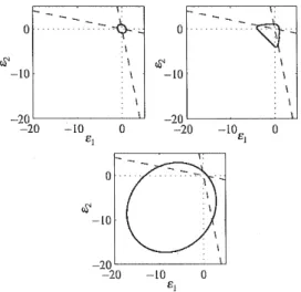
where ci are the principal strains and <ci> = Ei when ci > 0 and <ci> = 0 otherwise (Fig. 1 ). A third possibility, which is also mentioned by Peerlings, is the modified von Mises definition. It is written as follows
s-
k 1 /+ - 2k(l-2V) I (k-1)2 /2-~]
2k (l-2v)2 ' (l+v)2 2 (8)11 and ]z are the first invariant of the strain tensor
and the second invariant of the deviatoric strain tensor respectively. Only the modified von Mises criterion leads to a new material parameter, namely the factor k. The parameter k is the ratio between uni-axial compressive and uni-axial tensile strength.
This criterion is also plotted in Figure 1, with k =
10. The loading surfaces (Eqs. 6-8) are closed contours around the origin. The dashed lines represent the constant uni-axial compression and uni-axial tension stress paths.
\. \, 0 .... ~~.:-:-.~·:. 0 .... ~.~-:. :I W' '.I W' : I -10 I -10 I I I -20 I -20 I -20 -10 0 -20 -10 0 81 81 -20~---~1 -20 -10 0 81
Figure 1: Contour plots for
s
for the elastic stored energy (top left), Mazars definition (top right), and the modified von Mises expression (bottom), after Peerlings et al. (1998).The evolution of damage has the same form as in elasto-plasticity: if f(e,K)
=
0 andj(e,K)=
0 { c/=
h(K) . then _ where d ~ 0 K=
E (9) { d=O otherwise K=OThe function h(K) is specific, depending on different models. For tension only, exponential softening can be used and
(10)
where K0,a, 17 are model parameters. In order to
capture the differences of mechanical responses of the material in tension and in compression, Mazars proposed to split the damage variable into two parts and used the equivalent strain defined in Eq. (7):
(11)
where d1 and de are the damage variables in tension
and compression, respectively. They are combined with the weighting coefficients a1 and ae defined as function of the principal values of the strains c~ and
c~, due to positive and negative stresses (see Mazars, 1984). Strain 5 -0.008 -0.006 -0.004 -0.002 .!j. 00 0.002 -10; I -15 -20 !25 -30 -35 Stress (Mpa) _40
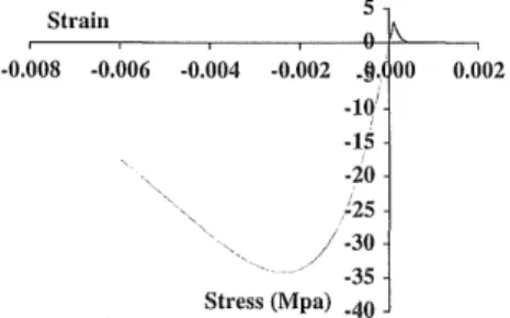
Figure 2: uniaxial response of the model by Mazars (1984).
In uniaxial tension a1=l and ae =O. In uniaxial
compression ae=l and a1=0. Hence, d1 and de can
be obtained separately from uniaxial tests. The evolution of damage is derived in an integrated form, as a function of the variable K:
3 PROGRESSIVE FAIL URE MODELLED WITH A DISCRETE APPROACH
The above approach of modelling progressive cracking in concrete may be viewed essentially as a phenomenological way to capture a phenomenon lying at the scale of cement paste and aggregate in concrete. It may then appear quite tempting to back this type of modelling with some analysis carried out at a lower scale. There are at least, two possibilities for such studies: the lattice analyses proposed e.g. by Van Mier and co-authors (Van Mier, 2000), or the discrete analyses as advocated by Hermann and
d =I - Ko(l-A)
I 1(
A1 exp( BJK - K0))'
A
(12)K0,Al'Bt'Ac,Be are the parameters in this model.
Figure 2 is an illustration of the uniaxial stress-strain response of the material with such a model.
Roux (1990). In these two kinds of approaches, there are some fundamental differences: in the first one, a discrete representation of the material is mapped on to the geometry of the structural element to be modelled. There is a direct, one to one, relation in between the lattice properties and the material constituents. For instance, the structural properties of each element of the lattice depend upon where the element is located: in the cement paste, in the aggregate, or across their interface. In the second approach, the lattice is not meant to represent any geometry at the structural level. Each element of the lattice has a random strength which is meant to represent local disorder in the material (cement paste, aggregate, interface). The case of a lattice of infinite size represents the thermodynamic limit at which the discrete lattice is equivalent to a continuum point. This is the reason why researchers are mostly interested by scale effects, when studying such lattices. These scale effects, as we will see further, provide some information on what should be incorporated in an equivalent continuum model. In this section we are going to recall briefly the main results obtained with this techniques, which are relevant to continuum damage modelling.
3.1 Discrete lattice analysis
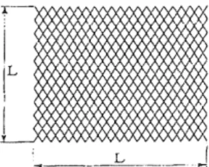
We are studying here a discrete system which is a regular two-dimensional lattice whose bonds are one dimensional (see Fig. 3). Complete details of this study can be found in (Delaplace et al., 1996). The lattice size is L x L where L is related to the total number of bonds n =
2!3.
Each bond behaves linearly up to an assigned threshold where brittle failure is reached. The model does not aim at describing a specific material. It ought to be the· simplest model whose thermodynamic limit (lattice of infinite size) should be described by the damage theory. Yet, this description includes the essential ingredients: a two dimensional geometry, initial disorder, interactions and redistribution as the number of broken bonds increases.~
I
\:IL
xx x ) Il
\ ,_. _ _ _ _ L _____ -J
Figure 3: Lattice used for the analysis (after Delaplace et al. 1996)
Instead of solving a mechanical problem, we use an electrical analogy which turns out to be strictly equivalent to the mechanical problem. The scaling properties of the mechanical problem and those of the electrical problem are identical (de Arcangelis and Herrmann, 1989).
The heterogeneity of the material properties is restricted to the variability of the maximum stress at failure. We have chosen here a distribution which is constant between 0 and l, hence it is representative of a large disorder which yields to diffuse damage which localises progressively. The boundary conditions at the limit of the lattice are periodic so that the behaviour of an infinite system is represented and boundary effects are avoided. A monotonically increasing vertical displacement is applied at the top of the lattice while the bottom face is fixed. The computational algorithm removes one bond at a time. In order to determine the next bond to be broken at a given step, we look for the bond where the stress is the closest to its peak stress. This bond will fail when the displacement is increased.
Note that there are two competing effects in the failure process: on one side, and because the material is disordered, bonds with a small strength fail first. On the other side, single crack propagation in the lattice produces a concentration of stress (e.g. at the crack tip) which may cause a bond with a high strength to fail. This illustrates how redistribution and disorder may compete during the failure process. Initially all local stresses are identical, and thus the first bond to break is the weakest. If the disorder is strong enough, the stress amplification in the vicinity of this first broken bond is not enough to induce a failure, and the second weakest bond may fail. This process yields diffuse damage. Eventually, at some stage, the stress heterogeneity due to the presence of a large density of broken bonds will dominate over the distribution.
Each lattice possesses a unique distribution of bond thresholds. Obviously, analyses cannot rely on a single realisation of the random process, which assigns the bond strength distribution. Several computations with different random seeds must be
performed and analysed in a statistical fashion. The envelope of the lattice responses agrees with continuous damage models. Figure 4 shows a 64 x 64 lattice at the inception of complete failure, when only one bond remains unbroken (i.e. when the lattice is about to separate into two pieces). As the number of broken bonds increases, their location localises over a tortuous line progressively - damage is diffuse at the beginning of the failure process and localises to form a macro crack. It is important to note that this localisation concerns the incremental damage. The final aspect of the distribution of micro cracks will appear as diffuse since it incorporates micro cracks generated at all stages.
Figure 4: Lattice just before complete failure (after Delaplace et al. 1996).
The numbers of broken bonds at peak and at failure are interesting because they show that damage is distributed. Would damage be localised along a single line (for brittle materials), the number of broken bonds at failure would be twice the system size, and the number of broken bonds at peak would be zero. This result would be achieved when there is no disorder in the lattice.
Table 1 shows for each different size of lattice considered the number of runs performed, the
L Runs n" nc 8 1000 19 29 16 500 76 105 24 250 149 198 32 250 255 340 64 30 947 1148
Table I: Number of broken bonds at peak and at failure as a function of the lattice size.
averaged number of broken bonds at the peak current (load) 11" and the averaged number of broken bonds at failure nc. It should be noted that the number of broken bonds at failure is always higher than the number of broken bonds at peak. This indicates that the failure process is rather progressive
and that the behaviour of the lattice departs from a brittle response due to spatial correlation and local disorder.
3.2 Global properties of the discrete model The global properties of the discrete model at any state of damage are, in this approach, directly connected to the local distribution of stress N(a).
Instead of characterising the distribution itself, valuable information can be obtained with the analysis of the moments of the distribution of the stress. The moment of order m is defined as:
M111
=
f
a"'N(a)da (13)These moments are of interest because of their physical meaning: the moment of order zero is the number of unbroken bonds. The first order moment is related to the average stress, the second order moment is proportional to the overall lattice stiffness
E:
M2
=
f
ra2
N(a)da
=
2GU2=
2G (14)where
r
is the local compliance of the bond and Uis the global displacement applied to the lattice.
It is natural to investigate whether the number of broken bonds is a variable, which characterises correctly the evolution of damage in the continuum sense, that is a degradation of the global stiffness. If
the number of broken bonds q I L2 (divided by the
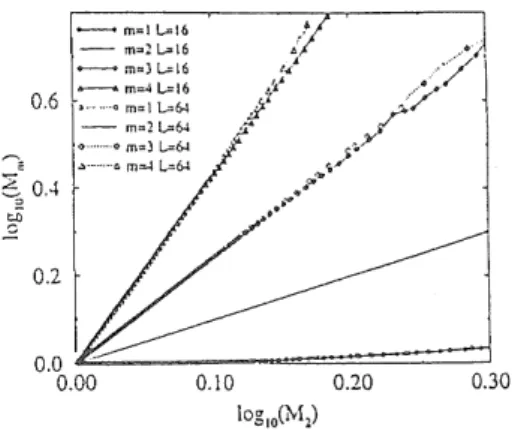
dimension of the lattice in order to have a quantity which is size independent) is the pertinent damage variable, the plots of the global conductance versus the non dimensional number of broken elements should be independent of the size of the discrete model. Delap lace et al. ( 1996) have shown that this is not true. Figure 4 shows a log-log plot of the moments as a function of the second order moment for different sizes of lattice. These plots do not depend on the size of the system, at least before the peak is reached. Hence, damage can be defined as the variation of the overall stiffness of the material. This result is a proof that progressive damage resulting from local brittle failure in disordered materials should indeed be modelled with the type of continuum model depicted in the previous section. A similar observation has been reported by Krajcinovic and Basista (1991 ). - m=I L=l6 - m=2[..,.16 ...-.. m=3 L=l6 0.6
~:~~~
- m=2L=64 ., ... m=3 l..=64 0.2 0.0 '£;;.;;::_ _ _ _ _ ~=~~::::::====i 0.00 0.10 0.20 0.30Figure 5: Evolution of the first four moments of the distribution of stress as a function of the overall stiffness (after Delaplace et
al. 1996).
3.3 Existence of a correlation length
Assume that there is a length denoted as ~ which defines the smallest size of the representative volume of the material (RVE). By definition, this length is smaller or equal to the size of the lattice. This quantity is a correlation length in a statistical sense. Above this size, the material can be regarded as homogeneous, i.e. without correlation. The local response of each bond in the discrete model is not independent for cells in the lattice below this size. In such cells, the response cannot be regarded as that of a homogeneous continuum. In order to exhibit the existence of a correlation length as the number of broken bonds increases, one can analyse their distribution over the lattice. This analysis is based on the variation of distance between two bonds in the lattice, which are consecutively broken during the loading history according to the foregoing definitions: the distance between to neighbouring vertical bonds is 1 because there are L bonds on each column of the cell, and the distance between two neighbouring horizontal bonds is 0.5 because there are 2L bonds on each row of the cell.
The histograms of the distribution of horizontal distance between two consecutive broken bonds denoted as h(d) can be approximated at least up to the peak: the distribution of the broken links is assumed to follow a power law function of the distance up to ~ and then it is a horizontal line. The length ~ corresponds then exactly to the smallest size of the RVE:
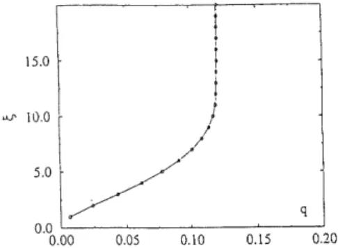
The distance <;' is also the length at which the distribution changes from diffuse damage (constant distribution) to a progressive localisation of damage. Hence, it can be considered as a measure of the size of the zone in which damage localises. The first order moment of the distribution h(d) can be obtained numerically. Substitution of Eq. (15) in the expression of the first order moment yields an equation where the only remaining unknown is the correlation length. 15.0
!
I
II
uJ' 10.0 /5.0//
q 0.0 '---'---"---'---~ 0.00 0.05 0.10 0.15 0.20Figure 6: Internal, correlation length vs. number of broken bonds (after Delaplace et al. 1996).
Figure 6 shows the evolution of this correlation length. It increases with increasing damage. The existence of a correlation length suggests that the damage process should be spatially con-elated. This result is among the ones, which motivate the introduction of an internal length in non local damage models. Other proofs lie in the micromechanics of interacting cracks (Bazant 1987, Pijaudier-Cabot and Berthaud 1990).
4 MORE ADVANCED ISSUES IN DAMAGE MODELLING
We are going now to recall some damage based constitutive relations which have been derived in order to enhance the sometimes simplistic description presented in section 2.
4.1 Damage model including a residual hysteretic behaviour
The natural form of damage can be represented using tensors of the order eight. However, the experimental identification is a tedious task. Aiming at a physical and realistic description of oriented crack growth in concrete, without neglecting
simplicity requirements, leads to the use of a second order damage tensor formulation (Mazars and Pijaudier-Cabot, 1989). In the latest model by Ragueneau et al. (2000), the stress tensor is seen as a superposition of an elasto-damage stress tensor and a sliding stress tensor. The elasto-damage part of the model is based on the work of Cordebois and Sidoroff (1979), who postulated for the definition of the effective stress an energy equivalence instead of the classical strain equivalence. Concerning the sliding part of the model, a new internal variable has been introduced, the sliding strain tensor
cs.
It is this sliding tensor which produces hysteretic effects.An elasto-damage effective strain
£
and a sliding effective strain8
depending only on the damage variable are defined (in these equations there are no sums on the indices):(16) (17)
Then the free energy is expressed as:
(18)
in which, µ and
A
are the initial Lame coefficients.au
is the hardening internal variable and b is a material parameter. The stress tensors can be derived as (no sums on indices):01/f (
)1/2 (
)1/2
CYu=p
08 IJ .. =2µ1-di cul-dj
+
Based on experimental investigations, damage for brittle materials like concrete is principally governed by its tensile behaviour. To take into account this phenomenon, two damage tensors have to be introduced. The splitting between the tensile and the compressive damage tensor is achieved through the
sign of the sliding strains expressed in their own principal directions :
(21) with
E sij -- E+ sij
+
E. sij ' Es +=
p-1 \Es I ") p - p-1 I ") p+ , Es
=
\Es _E.'.~j = diagonal sliding strain tensor and P is the transformation matrix.
H(x)
is the Heaviside function.For each principal direction, tensile damage is evaluated with the same type of evolution equations as in the isotropic model. Compressive damage is only considered as a consequence of the tensile behaviour of the material, and is taken equal to a function of the state of tensile cracking in the orthogonal directions.
(22)
where f3 is a material parameter depending on the damaged Young's moduli for two orthogonal directions. A typical value for concrete is, f3 = 12.
The sliding part of the constitutive relation is assumed to represent a plasticity-like behavior. In order to reproduce the hysteresis loops, nonlinear kinematic hardening is considered. The sliding criterion takes the following form:
(23) where
cr
Y is the initial yield stress, X is the backstress, and the dissipative potential is expressed as follows,
where 12 ((JS -
x)
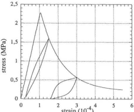
is the Von Mises equivalentstress, here chosen as a first approximation. /1 is the first invariant of the sliding stress tensor. The simulation of uniaxial tension is plotted in figure 7.
Figure 8 shows a result of stiffness recovery. A
major feature of this model is the coupling between damage and sliding effect.
This constitutive relation has been developed within a research project on seismic analysis of structures.
It has been shown that taking into account the
~ 1,5 ~
6
Ul Ul ~ ~ 0,5 0 0 2 3 4 strain (10-4) 6Figure 7: Tension response (after Ragueneau et al. 2000).
2,5 1,5 ~ 1 ~
6
0,5 Ul Ul 0~
-0,5 -1 -0,5 0 0,5 1 1,5 strain (1o·
4) 2,5Figure 8: Unilateral effects (after Ragueneau et al. 2000).
hysteretic response of concrete is more realistic than using artificial damping at the structural level. 4.2 A general class of damage models.
The above damage model introduces damage-induced anisotropy since upon damage propagation, the elastic response of the material is orthotropic. Damage-induced anisotropy is a feature of the material response, which is necessary when it is subjected to complex stress states. Fi chant ( 1997) devised a general approach to damage-induced anisotropy. The simple features of the microplane approach (Ozbolt and Bazant 1992, Carol et al. 1991) are combined with the approximation of damage surfaces, in the same spirit as in Ladeveze's approach (Ladeveze, 1983).
The effective stress denoted as <J~ is introduced according to the following definition:
rr'..
=
c~ E or (J1. = C.0 (c*)-l
(J (25)I) ljk/ kf I} ljkf kflllll lllll
Let us define now the relation between the stress and the effective stress along a finite set of directions denoted by unit vectors
ii:
a=
(1-
d(ii) )np~nj ,3, 2 (26)
r=(l-8(ii))
Ii(a~nj-ha~
1
n
1
)n;)
i=l
where
a
andr
are the normal and tangential components of the stress vector respectively. Two damage surfaces are introduced:where d(ii) and 8(ii) are scalar valued quantities which define the influence of damage on the relation between the effective stress vector and the stress vector. The basis of the model is the numerical interpolation of these damage surfaces. Damage coefficients are known for a finite set of directions, and interpolated between them. The stress is the unique solution of the virtual work equation:
f d m aii sue that h 't!cu * 4
n
*3
aucu=
(28)
where .Q is a unit sphere. The simplest approximation, which does not yield isotropy, corresponds to an ellipsoidal damage surface: this surface is characterised by three directions and by the values of three damage scalars di along these directions. The material behaviour is orthotropic when d1-:/= d2-:/= d3 • The principal directions of orthotropy are those of the damage surface.
The damage surface is initially a sphere of radius 1 (d(ii)
=
0). For the isotropic and orthotropic damage models, the evolution of damage is controlled by the same loading surfacef:
f
(ii)= iisii - sd - X(ii) (29) where X is a hardening - softening variable which is interpolated in the same fashion as the damage surface (i.e. as a sphere or an ellipsoid). The threshold of damage is given by the strain cd. The evolution of the damage surface is defined by the following set of equations:if
!(ii*)= 0 and ii* eii* > 0 {d(ii*) =a exp(-a(ii* en' - cd )ii* En*
then
i<
ii* J =ii* eii* else d(ii*)=
0, j(ii*)=
0(30)
where a is a model parameter. Note that the vectors
ii* are the three principal directions of the incremental strain. Since the principal directions if the incremental strains are not necessarily those of the total strain, rotation of the principal axes of damage is naturally obtained.
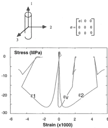
When the loading history is more complex, elasto-plastic coupling and damage deactivation can be incorporated in this damage model (Fichant et al. 1999). Figure 9 shows a typical uniaxial compression-tension of this anisotropic model.
I
!-
[
crl 0 OJ
cr= o o o 0 0 0 Stress (MPa) -10( ,f)
-20 -30 '----'----L--~--'----L-__J -6 -4 -2 0 2 Strain (x1000)Figure 9: Uni axial tension-compression response of the anisotropic model (after Fichant et al. 1999).
4. 3 Damage and smeared crack models
Historically, smeared crack models have been developed for modelling concrete fracture fifteen years before continuous damage models started to become popular. In smeared crack models the directionality of the material decohesion is a fundamental characteristic, which was not included into the first damage models (such as the simple damage model reviewed in section 2). On the other side, most damage models were cast in such a way that rate independent plasticity and viscoplasticity could be easily coupled to damage, thus expanding their field of applicability to cases where cracking is not the single dissipative phenomenon in the material response. In this respect, it should be underlined that continuous damage theories benefited from a large bulk of research results in the field of composites, metal alloys and ceramics which encompassed the quasistatic response of the material but also fatigue and tertiary creep (Lemaitre, 1992).
induced anisotropy is almost a settled issue in damage modelling. At least, one knows how to model it. Then it is nat{1ral to relate these damage models to smeared crack models (de Borst and Gutierrez, l 999).
In the latter model, the material response is defined in a local coordinate system ( n, s ). Direction n is the normal to the plane in which the greatest positive normal strain denoted as £
1111 is found. In the ( n,s) system, the secant stress-strain relation is:
a11,s = D;;""811.s (31)
with all,S = [a/Ill ass a/IS
r·,
£11,S = [ £1111 E,\'S £/IS]T,
and the secant stiffness
D;;",
is(l-d1)E (l-d1)vE 0 1-(1-d1 )vz 1-(l-d1)Vz
D;; .. ,=
(l-d1)vE E 0 (32) 1-(l-d1)Vz 1- (l-d1)Vz 0 0 (l-dz)Gwhere d1 and dz are two damage parameters. (1- dz) is the degradation of the shear stiffness G and can be related to the shear retention factor in traditional smeared crack models. The evolution of these two damage parameters is defined with the help of a loading function in the ( n, s) coordinate system : f(£1111,K) = £1111 - K and the appropriate
Kuhn - Tucker conditions. d1 and dz are functions of the history variable K, same as in the other damage models.
If we introduce ¢ as the angle between the ( x, y) coordinate system and the ( n, s) coordinate system, the strain and stress components in the two systems can be related as follow:
where ~(¢) and Ta(</J) are the appropriate transformation matrices. The secant relation in Eq. (31) becomes:
(34) This equation, and the loading function f(E,111,K)
incorporate the fixed smeared crack model and the rotating crack model as well. The difference is that in the fixed crack model the angle ¢ is constant whereas in the rotating crack model, the coaxiality requirement enforces that the n-direction is always the major principal strain direction.
As we can see, smeared crack models are indeed damage models, with two damage coefficients and some rule upon which the principal directions of damage may change. In the fixed crack model, the principal directions of damage are fixed, in the rotating crack model, they rotate according to the condition of coaxiality. The fundamental difference with the anisotropic damage model devised in section 4.1 is that damage variable does not have necessarily to be a tensorial expression.
There is, however, a similarity between the above formulation of the smeared crack model and microplane-based damage models. The integral which defines the overall stress in the microplane model, is the same as in the model by Fichant (Eq. 28). This integral can be transformed in order to arrive to a format which is very similar to the multiple fixed crack model:
where
w"
is a weighting factor.5 NON LOCAL AND GRADIENT DAMAGE We turn now attention to the non local generalisation of damage models. It is now established that non locality, in a gradient or integral format, is mandatory for a proper, consistent, modelling of fracture. It avoids the difficulties encountered upon material softening and strain localisation. Within a single approach, it encompasses both crack initiation (for which continuum models are very well fitted) and crack propagation (for which discrete fracture approaches have been developed).
5.1 Nonlocal damage model
Consider for instance the scalar damage model in which evolution of damage is controlled by the equivalent strain
e
introduced by Mazars. The principle of nonlocal continuum models with local strains is to replacee
with its average (Pijaudier-Cabot and Bazant, 1987):- 1
-E(x) = lfl(s)E(s
+
x)ds V,.(x)with V,.(x) =
f
lfl(s)ds (36)where Q is the volume of the structure, v;.(x) is the representative volurl}e at point x, and lfl(s) is the weight function, for instance:
lfl(s) =exp(-
411~112)
[c
(37)
le is the internal length of the non local continuum. 8 replaces the equivalent strain in the evolution of damage. In particular, the loading function becomes
f(£,K) = £ - K. It should be noticed that this model is easy to implement in the context of explicit, total strain models. Its extension to plasticity and to implicit incremental relations is awkward. The local tangent stiffness operator relating incremental strains to incremental stresses becomes non symmetric, and more importantly its bandwidth can be very large due to non local interactions. This is one of the reasons why gradient damage models have become popular over the past few years.
5.2 Gradient damage model
A simple method to transform the above non local model to a gradient model is to expand the effective strain into Taylor series truncated for instance to the second order:
- - ae(x) a2e(x) s2
s(x + s)
=
s(x) + - - s + - -2- - + ... (38)ax ax 2!
Substitution in Eq. (38) and integration with respect to variable s yields:
(39) where c is a parameter which depends on the type of weight function in Eq. (39). Its dimension is L2 and it can be regarded as the square of an internal length. Substitution of the new expression of the nonlocal effective strain in the non local damage model presented above yields a gradient damage model. Computationally, this model is still delicate to implement because it requires higher continuity in the interpolation of the displacement field. This difficulty can be solved if an implicit format of the gradient damage model is used. Eq. (39) is replaced with
(40) Here, the definition of the non local equivalent strain is implicit. It is the solution of a Fredholm equation. As shown by Peerlings et al. (1996), Eqs (39,40) are
equivalent, but the implicit form is in fact an exact representation of the integral relation devised by Pijaudier-Cabot and Bazant, provided an exponential weight function is used. Gradient damage models have also been devised differently. Fremond and Nedjar (1993) started from the principle of virtual work adding the power of internal forces involving higher order terms. A more recent approach, inspired by the mechanics of porous materials, was proposed by Pijaudier-Cabot and Burlion (1996).
This implicit equation which defines the nonlocal effective strain as a function of the local effective strain is easy to discretise in a finite element scheme. The implementation of the gradient damage model becomes in fact similar to the implementation of a thermomechanical (local) model in which the nonlocal effective strain replaces the nodal temperatures.
5.3 Extension to anisotropic gradient damage In the anisotropic damage models described in section 4, the evolution of damage is directional. The evolution of damage is also directional in the microplane-based models and in the smeared crack models. The extension of the gradient damage model to anisotropy is quite straightforward in this context. For instance the loading function
f(c
1111,K) in thefixed smeared crack model may become:
This extension is also straightforward in the context of microplane models where directions ii are defined arbitrarily and fixed in the analysis. For each direction in which damage growth is defined, a nonlocal variable is introduced. There are as many nonlocal variables as directions considered and these variables are interpolated throughout the finite element mesh, same as for the isotropic gradient damage model. The usual set of equilibrium equations is complemented with p x m equations where p is the number of directions and m is the number of damage variable per direction (Kuhl et al., 1998).
For the orthotropic damage model proposed by Fi chant et al. ( 1997), three directions are considered only at each material point. The directional distribution of damage is reconstructed by interpolation in between those principal directions. Hence, there is the complexity that the directions change from one finite element to another and might rotate in the course of loading too. A similar problem is encountered in nonlocal rotating crack models (de Borst, 1999). Conceptually, this feature
does not change anything in the discretisation, except that one has to keep track of the orientation of principal directions of damage. This is in fact the price to pay for the reduction of equations (and degrees of freedom) to be solved.
5.4 Size effects in non local models
A salient characteristic of non local models is the size effect. Because the constitutive relations contain a length scale, the response of geometrically similar specimens is not geometrically similar. In fact, the internal length scale controls the size of the fracture process zone (FPZ), in which micro-cracking occurs during failure. Hence, the size of the FPZ is a model characteristics, which is not dependent on the structure size. It follows that the ratio of the FPZ size to the structural size varies when geometrically similar specimens are tested. This variation produces a size effect, which may be modelled with simple equations proposed by Bazant (see the review by Bazant and Planas, 1998).
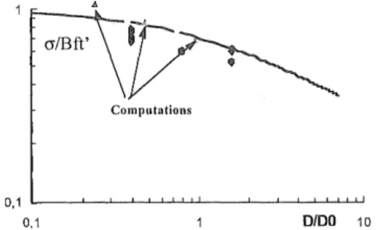
Let us consider as an example the case of three-point bending of geometrically similar notched beams. Geometrically similar specimens of various height D = 80, 160, and 320 mm, of length L = 4D, and of thickness b = 40 mm were tested by Le Bellego (2001 ). The length-to-height ratio is LID 4 and the span-to-height ratio is !ID = 3. Figure 10 shows the beam deflection response for the three sizes and Figure 11 shows the plot of the nominal stress as a function of the structure size (Le Bellego et al. 2000). For this computation, the non local integral model depicted above has been used and the model parameters have been fitted on these data. A gradient damage approach would yield exactly the same type of result (de Borst and Gutierrez, 1999).
The prediction of size effects is today the most robust way to achieve the experimental determination of the internal length. In fact, it is not possible to predict numerically the size effect depicted in this paper with a local model. This kind of experiment provides also an indirect proof that an internal length ought to be introduced in the constitutive relations. It can be done with the help of a non local formulation or in the context of a cohesive crack model, with the same success in the case of simple mode 1 crack propagation.
6 CONCLUDING REMARKS
Damage models, smeared crack models and microplane models can be cast in the same unified framework aimed at a phenomenological description of progressive failure in concrete and other
quasi-1000 force (daN) 900 800 700 600 500 400 300 200 100 0 0, 1 0,2 0,3 0,4 0,5 dellexion (mm)
Figure 10: Fit of the non local model with the size effect test data (after Le Bellego et al. 2000).
Computations
0.1 0/00 10
Figure 11: Comparisons between the experiments and the computations on the size effect plot (upper and lower bounds of the fit of experimental data appear on this graph) (after Le Bellego et al. 2000).
brittle materials. Already, we have shown that complex phenomena such as hysteretic effects, damage deactivation or damage induced anisotropy could be folded in this modelling. This framework needs, no doubt, to be enhanced with the information obtained from discrete analyses, where complex effects such as aggregate interlock, boundary effects, crack sliding, and the influence of the respective properties of the each component entering in concrete can be analysed.
The non local extension of these advanced models may raise some computational difficulties, and to this respect the scalar damage approach still offers a simple but robust way to model fracture in a continuum description. This may be the reason why this simple model is very often preferred whenever coupled mechanical and environmental effects are considered in the analysis of concrete structures. A good understanding of damage processes induced by such environmental actions and their interaction with mechanical damage is certainly one of the important questions, which remain to be addressed in damage mechanics applied to concrete fracture. Acknowledgements: This review paper has been collected from research that the authors carried with many collaborators. A. Delaplace, S. Fichant, B.
Gerard, M. Guttierez, C. La Borderie, C. Le Bellego, R. Peerlings, F. Ragueneau, and S. Roux took an important share iff these efforts and should be gratefully acknowledged.
7
REFERENCESBazant, Z.P. (1987), Why continuum damage is non local: Justification by quasi-periodic crack array, Mech. Res. Comm., Vol. 14, pp. 407-419.
Bazant, Z.P. and Planas, J. ( 1998), Fracture and size effect in concrete and other quasibrittle materials, CRC Press. Carol, I., Bazant, Z.P., and Prat, P.C. (1991), Geometrical
damage tensor based on microplane model, J. of Engrg. Mech. ASCE, Vol. 117, pp. 2429-2448.
de Borst, R. ( 1999), Isotropic and anisotropic damage models for concrete fracture, in Mechanics of Quasi-Brittle Matrials and Structures, G. Pijaudier-Cabot et al. Eds., Hermes Sci. Pubs., pp. 39-56.
de Borst, R. and Gutierrez, M. ( 1999), A unified framework for concrete damage and fracture models including size effects, Int. J. Fracture, Vol. 95, pp. 261-277.
Cordebois, J.P., and Sidoroff, F. ( 1979), Damage induced elastic anisotropy. Proc. Euromech Coll. 115. Villars de Lans, pp. 761-774.
De Arcangelis, L., and Herrmann, H. J. (1989), Scaling and multi-scaling laws in random fuse networks, Phys. Rev. B, Vol. 39, pp. 2678-2684.
Delaplace, A., Pijaudier-Cabot, G., and Roux, S. (1996), Progressive damage in discrete models and consequences on continuum modelling, J. Mech. Phys. Solids., Vol. 44, pp. 99-136.
Fichant, S., Pijaudier-Cabot, G. and La Borderie, C. (1997), Continuum damage modelling: approximation of crack induced anisotropy, Mechanics Research Communications, Vol. 24, pp. 109-114.
Fichant, S., La Borderie, C., and Pijaudier-Cabot, G. (1999), Isotropic and Anisotropic Descriptions of Damage in Concrete Structures, Int. J. Mechanics of Cohesive Frictional Materials, Vol. 4, pp. 339-359.
Fremond, M., Nedjar, B. (1993), Endommagement et principe des puissances virtuelles. Comptes Rendus Acad. Sci., serie
II, pp. 857-864.
Herrmann, H. J., and Roux, S. (Eds) ( 1990), Statistical models for the fracture of disordered media, Noth-Holland, Amsterdam.
Krajcinovic, D. and Basista, M. (1991), Rupture of central force lattices revisited, J. Physique, Vol. 1, pp. 241-245. Kuhl, E., Ramm, E., and de Borst, R. (1998), Anisotropic
damage model with the microplane model, in Computational Modelling of Concrete Structures, de Borst et al. Eds., Balkema Pubs, pp. 103-112.
Le Bell ego, C. (2001 ), Couplages chimie-mecanique dans Jes structures en beton attaquees par l'eau: Etude experimentale et analyse numerique, These de doctorat de !'ENS Cachan, France.
Le Bellego, C., Pijaudier-Cabot, G., and Gerard, B. (2000), Coupled mechanical and chemical damage in concrete structures, in Continuous damage and fracture, A. Benallal Ed., Elsevier Pubs. Pp. 397-407.
Ladeveze, P. (1983), Sur une theorie de l'endomagement anisotrope, Int. Report n. 34, Laboratoire de Mecanique et Technologie, Cachan, France.
Lemaitre J. ( 1992), A Course on damage mechanics, Springer Verlag.
Mazars J., ( 1986). A description of micro- and macroscale damage of concrete structures. Journal of Engineering Fracture Mechanics. Vol. 25, No. 516, pp. 729-737. Mazars, J., Application de la mecanique de l'endommagement
au comportement non lineaire et
a
la rupture du beton de structure, These de Doctorat es Sciences, Universite Paris VI, Paris, France, 1984.Mazars, J. and Pijaudier-Cabot, G. (1989), Continuum Damage Theory- Application to Concrete, J. Eng. Mech. ASCE, Vol. 115, pp. 345-365.
van Mier, J.G.M. (2000), Measurement of damage parameters in brittle disordered media like concrete and rock, in Damage and fracture of disordered materials, D. Krajcinovic and J.G.M. Van Mier Eds., Springer Pubs, pp. 135-178.
Ozbolt, J., and Bazant, Z. P. (1992). Microplane model for cyclic triaxial behaviour of concrete. J. Engrg Mech. ASCE, Vol. 118, pp. 1365-1386.
Peerlings, R.H., de Borst, R., Brekelmans, W.A.M., de Vree, J.H.P. (1996), Gradient enhanced damage for quasi-brittle materials, Int. J. Num. Meth. Engrg., Vol. 39, pp. 3391-3403.
Peerlings, R.H., de Borst, R., Brekelmans, W.A.M, Geers, M.G.D., Gradient enhanced modelling of concrete fracture, Int. J. Mechanics of Cohesive Frictional Materials, Vol. 3, pp. 323-343.
Pijaudier-Cabot, G., and Bazant, Z.P. (1987), Non local damage theory, J. of Engrg. Mech. ASCE, Vol. 113, pp. 1512-1533.
Pijaudier-Cabot, G. and Berthaud, Y. (1990), Effet des interactions dans l'endommagement d'un milieu fragile. Formulation non locale, Compte rendus Acad. Sci., t. 310, pp. 1577-1582.
Pijaudier-Cabot, G., and Burlion, N. (1996), Damage and localisation in elastic materials with voids, Int. J.
Mechanics of Cohesive Frictional Materials, Vol. 1, pp. 129-144.
Ragueneau, F., La Borderie, C., and Mazars, J. (2000), Damage model for concrete-like materials coupling cracking and friction, contribution towards structural damping: first uniaxial applications, Int. J. Mechanics of Cohesive Frictional Materials, Vol. 5, pp. 607-626.