HAL Id: hal-02124512
https://hal.archives-ouvertes.fr/hal-02124512
Submitted on 9 May 2019
HAL is a multi-disciplinary open access
archive for the deposit and dissemination of
sci-entific research documents, whether they are
pub-lished or not. The documents may come from
teaching and research institutions in France or
abroad, or from public or private research centers.
L’archive ouverte pluridisciplinaire HAL, est
destinée au dépôt et à la diffusion de documents
scientifiques de niveau recherche, publiés ou non,
émanant des établissements d’enseignement et de
recherche français ou étrangers, des laboratoires
publics ou privés.
Efficient Arbitrary Sample Rate Conversion for
Multi-Standard Digital Front-Ends
Ali Zeineddine, Stéphane Paquelet, Amor Nafkha, Pierre-Yves Jezequel,
Christophe Moy
To cite this version:
Ali Zeineddine, Stéphane Paquelet, Amor Nafkha, Pierre-Yves Jezequel, Christophe Moy. Efficient
Ar-bitrary Sample Rate Conversion for Multi-Standard Digital Front-Ends. IEEE NEWCAS Conference
2019, Jun 2019, Munich, Germany. �10.1109/NEWCAS44328.2019.8961230�. �hal-02124512�
Efficient Arbitrary Sample Rate Conversion for
Multi-Standard Digital Front-Ends
Ali Zeineddine
∗§, St´ephane Paquelet
†, Amor Nafkha
‡and Pierre-Yves Jezequel
§, Christophe Moy
¶∗TDF, Direction Technique Rennes, F-35510, Cesson-S´evign´e, France †Institut de Recherche Technologique b-com, , F-35510, Cesson-S´evign´e, France
‡SCEE/IETR UMR CNRS 6164, CentraleSup´elec campus de Rennes, F-35510 Cesson-S´evign´e, France §TDF, Centre de mesures d’antennes, F-35340, Liffr´e, France
¶Univ Rennes, CNRS, IETR - UMR 6164, F-35000, Rennes, France
Abstract—In this paper, we study the hardware implementa-tion of arbitrary sample rate conversion (ASRC) using recently proposed variable fractional delay filter (V-FDF) structures. The most commonly used solution to implement V-FDFs has been the Farrow structure for the last three decades. In this work, we develop and compare the implementations of different recently proposed V-FDF options based on the Newton structure. These implementations are done on both ASIC and FPGA targets. The obtained results show that the recently proposed solutions offer better ASRC performance while using up to 3 times less resources relatively to the classical Farrow structure. The generic nature of these filters make them suited for a large number of standards.
Index Terms—Arbitrary Sample Rate Conversion, Digital Front-End, Newton Structure
I. INTRODUCTION
For many years, the evolution of digital signal processing (DSP) in telecommunication systems has been focused on improving processing power performance. Recently, more focus is increasingly given to improving the system’s energy efficiency, and to building lower cost hardware. One of the main motivators of this trend is the evolution of the Internet of Things (IoT) domain, where billions of devices and their corresponding gateways are being deployed. To make this deployment possible at an acceptable cost, both devices and gateways need to be maximally optimized. A main part of every telecommunication system is the interface between radio frequency and baseband domains, implemented digitally in modern systems and known as the digital front-end (DFE) [1]. The DFE has two main roles, sample rate conversion (SRC) and filtering [2]. In this work, we are concerned with SRC. Two types of SRC exist in the DFE. The first is coarse SRC, where the sampling rate is increased or reduced by an important integer factor. The other type is known as fine SRC or arbitrary sample rate conversion (ASRC). Generally, fine SRC is more complicated to implement than coarse SRC due to the extra required precision.
To implement arbitrary sample rate conversion, a variable fractional delay filter (V-FDF) is the most efficient solution. The Farrow structure [3], dating back to 1988, is the most widely adopted implementation option that is found in most of today’s systems. An advantage of this structure is its capability of implementing any ASRC operation, with a reconfigurable
conversion factor. However more efficient structures can be found in the literature. In 2009, the Newton structure [4] was adapted to ASRC in [5], however limited to the filtering response of Lagrange interpolation. Later more recent work generalized this structure to Spline and Hermite interpolations [6][7]. Hermite interpolation is better adapted to the context of DFE, due to its wide pass-band and good SRC image rejection performance.
In this paper we aim to investigate the practical hardware complexity of these recently proposed solutions. The rest of the paper is organized as follows. Section II presents an overview of both the most common classical SRC solutions in modern DFE systems, and the recently proposed Newton struc-tures. In Section III, the implementation methodology based on the pipelined approach is developed, and the hardware architecture model is detailed. In Section IV, we implement the developed architectures on both FPGA and ASIC targets. We then compare the Hermite based Newton structures to the modern SRC solutions in both terms of complexity and performance. The conclusion is finally presented in Section V.
II. ASRC SOLUTIONS FORDFE SYSTEMS
One of the main DFE roles in modern transceiver systems is adapting the sampling rate between the radio frequency and baseband domain [1][2]. This conversion is done practically using both coarse and fine-tuned SRC modules. The SRC operation can be used multiple times in the same DFE of a radio transceiver. Moreover, fine SRC have other applications in the DFE, most notably for implementing synchronization functions. Therefore, ASRC modules are a main part of today’s transceivers, and their implementation efficiency plays an important role in optimizing the total system.
We usually find the coarse SRC implemented using cascaded-integrator-comb (CIC) filters [8], due to their effi-cient structure consisting of only registers and adders. How-ever, the CIC filters cannot implement all kind of SRC operations, and are only practical for coarse factor SRC. In the case of fine-tuned SRC, ASRC modules are required, and the Farrow structure is the most common solution [3]. This structure implements a polynomial based V-FDF. Polynomial based means that the filter impulse response is constructed
ASRC Module ASRC Controller input samples Sampling Rate #1 sample i µi U D CLK V-FDF Module output samples Sampling Rate #2
Fig. 1. Simplified high-level architecture of the ASRC module
using polynomials pieces. A V-FDF filter finds the value of the signal at variable instants defined by a given input µ.
To perform the ASRC operation, the value ofµ is updated for every output sample, as explained in [5]. The µ value is then used by the V-FDF to calculate the value of the corresponding output. In practical implementations, there are two important points to consider. First, the number of input and output samples is different, since the sampling rate is modified. Second, the hardware module operates at a single digital clock rate higher than both the input and output sampling rates. Therefore a control module is required alongside the V-FDF to manage the samples stream, and to calculate the required output instant µ for each sample. This control function is configured using the input up-samplingU and down-sampling D parameters representing the SRC factor R = U/D. The proposed ASRC module architecture is shown in Figure 1.
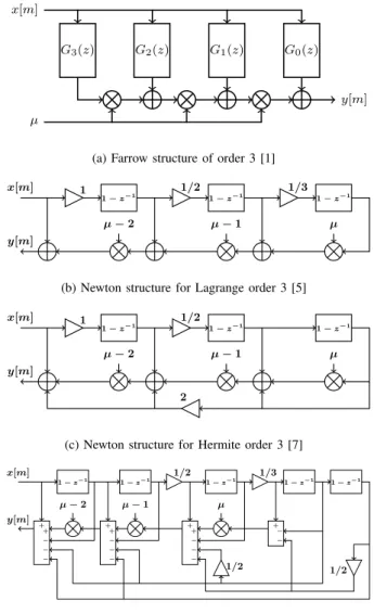
The implementation of the V-FDF using a Farrow structure of order 3 is shown in Figure 2-a. This structure consists of multiple FIR filters Gi(z) that have their outputs multiplied
byµ according to the Horner scheme, to find the final output y[m]. For a theoretical understanding of the structure, the reader can refer to [3] and [9]. The Farrow structure can imple-ment any polynomial-based filter response, however the most simple and commonly used option is Lagrange interpolation. To achieve side lobes rejection levels of at least 30 dB, an order 5 is required.
A structure developed in [5] modified the original Newton structure [4] into a V-FDF form compatible with ASRC. The structure of order 3 is shown in Figure 2-b. Compared to the Farrow structure, the Newton structure is designed for Lagrange interpolation only. However structurally, an order N interpolation can be achieved with a complexity of order O(N ) through the Newton structure, compared to a quadratic order of complexity O(N2) for the Farrow structure. Later
work extended the Newton structure to implement Spline [6] and Hermite [7] interpolation. Spline interpolation is not very interesting for multi-standard DFE systems due to its very small passband, and its bad scaling with interpolation order. On the other hand, Hermite interpolation keeps the same passband of Lagrange interpolation, while offering superior side lobes rejection level. At the same time, the Hermite based Newton structures offer lower complexity by eliminating the need for some multipliers. The Hermite based Newton structures of order 3 and 5 are shown in Figure 2-c and Figure 2-d respectively.
These two architectures are very promising from a structural level point of view. In this paper, we are interested in
investi-G3(z) G2(z) G1(z) G0(z)
x[m]
µ
y[m]
(a) Farrow structure of order 3 [1]
x[m] 1 1− z−1 y[m] µ− 2 1/2 1− z−1 µ− 1 1− z−1 1/3 µ
(b) Newton structure for Lagrange order 3 [5]
x[m] 1 1− z−1 y[m] µ− 2 1/2 1− z−1 µ− 1 1− z−1 µ 2
(c) Newton structure for Hermite order 3 [7]
x[m] 1− z−1 y[m] µ− 2 + + − − − 1/2 1− z−1 µ− 1 + + − − − 1− z−1 1/3 µ + + − − − 1− z−1 + − − 1− z−1 1/2 1/2
(d) Newton structure for Hermite order 5 [7]
Fig. 2. V-FDF module implementation options for (a) Farrow order 3, (b) Newton Lagrange order 3, (c) Newton Hermite order 3, (d) Newton Hermite order 5
gating the hardware implementation complexity of these recent structures, and compare them to the modernly used ASRC solutions. In the next section, we develop the methodology we used to implement these structure in order to compare their complexity on both ASIC and FPGA targets.
III. HARDWAREIMPLEMENTATIONMETHODOLOGY
This section develops the implementation approach used to obtain the results discussed in Section IV. The complete filter is composed of two modules, the controller and the V-FDF filter. As discussed in the last section, the controller is responsible for managing the SRC operation, while the V-FDF filter is only responsible for calculating the output samples.
To implement the ASRC controller, a finite state-machine (FSM) is the most appropriate approach. This FSM has theU and D parameters as inputs. The control FSM has 4 states, starting from the initial IDLE state, the FSM may be in the NEUTRAL state when there is only one sample output corresponding to the current input. The FSM may also be
in the INTERPOLATION and DECIMATION states when more outputs than inpust or the opposite conditions exist respectively. The value of µ is continuously updated to keep track of the output sample time delay.
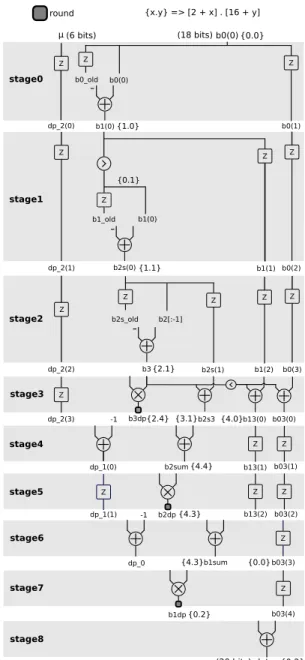
Since there could be more outputs than inputs or vice versa, a mechanism to block or advance the samples stream at certain instants is needed. In this work we used a handshake protocol based on “ready to send and receive” signals. Each module is responsible of signaling its own status. Between the controller and the V-FDF filter modules, extra control signals are used to signal if a register update or a new calculation is required. To implement the V-FDF module, we use the pipeline approach that is the most adapted for multi-standard DFE, where processing speed is privileged. The pipeline approach consists of breaking the filter structure into stages, with each stage containing only one calculation operation. This has the objective of minimizing the critical path length, and maximizing thereby the maximum operation frequency. The pipeline architecture for the modified Newton structure for Hermite interpolation of order 3 is shown in Figure 3.
The quantization of this implementation is done using fixed point representation. The signal’s quantization parameters are found by developing the analytical expression of the quan-tization error [10]. This expression is then used to find the signal to quantization noise ratio (SQNR). The optimal quan-tization parameters are then found using exhaustive research for a given SQNR. Considering for example an input signal quantized on 2 and 16 bits for the integer and fractional parts respectively, Figure 3 shows the quantization parameters for tolerated SQNR degradation of less than 0.6 dB. This quantity is chosen in order to have negligible deterioration of the effective number of bits due to quantization. The signals are quantized relatively to the input, where the number of added bits for integer and fractional parts is shown between braces, e.g. {x.y} → (2+x.16+y). For the fractional delay µ quantization on 6 bits, we referred to the work presented in [11]. Finally, the U and D parameters are quantized on 18 unsigned bits for an ASRC precision of 5 ppm.
Using the approach developed above, the hardware imple-mentations of the different V-FDF options shown in Figure 2 are developed with the same quantization performance. An implementation of the CIC filter is also developed to compare the complexity between fine and coarse SRC solutions.
IV. IMPLEMENTATIONRESULTS ANDDISCUSSION
We start the discussion by comparing the filtering perfor-mance of the different structures. The objective of an SRC filter is to remove the signal images on the multiples of the input sampling frequency Fs. As it is shown in Figure 4,
the first side lobe attenuation for Lagrange interpolation of order 5 is around−33 dB. However for both cases of Hermite interpolation of order 3 and 5, we find a side lobes rejection improvement by around 10 dB. All three responses have a maximally flat passband, and zeros on multiples of Fs. The
only major compromise is the Hermite interpolation of order 3 having weaker zeros. However this may be tolerable for certain
stage0 stage1 stage2 stage3 stage6 stage7 stage8 round {x.y} => [2 + x] . [16 + y] stage5 stage4 (6 bits) (18 bits) (20 bits) Z Z Z Z Z Z Z Z Z Z Z Z Z Z Z Z Z Z Z Z b0(1) b0(0) μ b1(0) b1_old b1(0) b1(1) b2[:-1] b2s_old b2s(1) b3 dp_2(1) dp_2(0) dp_0 b2sum b1dp b0(0) -1 dat_o b2dp dp_1(1) b0(2) b1(2) b0(3) b03(2) b03(3) b03(4) b0_old -1 dp_2(2) b3dp dp_2(3) dp_1(0) b1sum b2s3 b13(0) b03(0) b13(1) b13(2) b03(1) b2s(0) {0.0} {1.0} {0.1} {1.1} {2.1} {2.4} {3.1} {4.0} {0.0} {4.4} {4.3} {4.3} {0.2} {0.2}
Fig. 3. Pipeline architecture of Newton Structure for Hermite order 3
SRC applications that do not have high image attenuation requirements, which is the case of the SRC modules in the DFE that come after the filtering operations.
To develop the ASIC implementation, we used the Cadence Encounter tools with the X-FAB XH018 technology. The results are resumed in Table I. The implementations were optimized to operate at 180 MHz. It is seen that implement-ing Lagrange interpolation usimplement-ing the Newton structure only requires 70% the resources used by the reference Farrow structure. However, the Newton Hermite structure of order 5 requires less than half of the resources while offering a superior filtering response. Moreover, when using the Hermite order 3 response is tolerable, it is possible to implement fine SRC operations at a similar cost of coarse SRC CIC filters, with a reduction of complexity by a factor of three compared to the Farrow reference. The dynamic power draw of the
TABLE I
ASIC IMPLEMENTATIONRESULTSUSING THEX-FAB XH018 TECHNOLOGY
Module Gate Count Core Surface Transistors Count Complexity % Max. Frequency Core Power Farrow Lagrange 5 27328 950 × 950 µm2 243937 100% 180 MHz 362 mW Newton Lagrange 5 19824 800 × 800 µm2 175475 70.9% 179 MHz 251 mW Newton Hermite 5 14803 660 × 660 µm2 122838 48.3% 180 MHz 187 mW Newton Hermite 3 10903 540 × 540 µm2 84520 32.3% 180 MHz 134 mW CIC Spline 5 8299 510 × 510 µm2 73768 28.8% 180 MHz 113 mW TABLE II
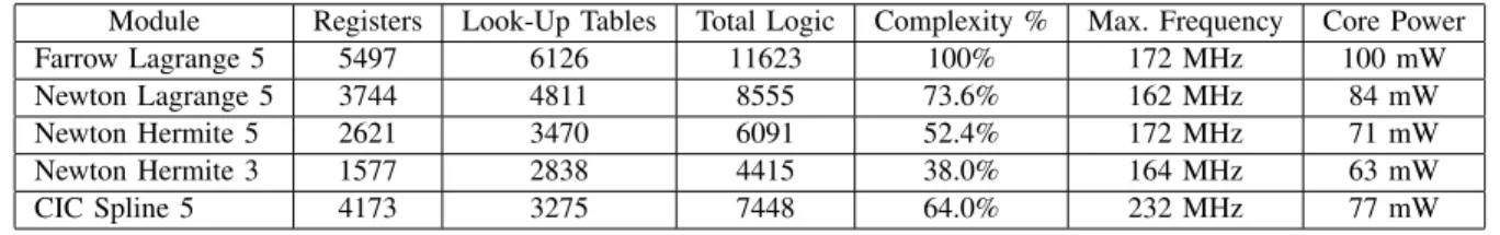
FPGA IMPLEMENTATIONRESULTSUSING THEXILINXVIRTEX-6 XC6VLX365T
Module Registers Look-Up Tables Total Logic Complexity % Max. Frequency Core Power Farrow Lagrange 5 5497 6126 11623 100% 172 MHz 100 mW Newton Lagrange 5 3744 4811 8555 73.6% 162 MHz 84 mW Newton Hermite 5 2621 3470 6091 52.4% 172 MHz 71 mW Newton Hermite 3 1577 2838 4415 38.0% 164 MHz 63 mW CIC Spline 5 4173 3275 7448 64.0% 232 MHz 77 mW
ASIC cores is estimated using Encounter RTL Compiler for an operating frequency of 180 MHz, a signal toggle rate of 20 MHz, and 1.8V core voltage.
For the FPGA implementations, we used the Xilinx Virtex-6, that gave the results shown in Table II. The dynamic power draw of the SRC cores in this case are estimated using Xilinx Power Estimator (XPE) for an operating frequency of 160 MHz, a signal toggle rate of 20 MHz, and 1.0V core voltage. The objective is not to compare the ASIC and FPGA implementations, but rather to study the implementation complexity on FPGA. The order of complexity between the Newton and Farrow structures stay the same, however the implementation of a CIC filter using look-up tables on an FPGA is not optimal, where the relative complexity is much larger on FPGA than on ASIC. Regardless, the results clearly show that the Hermite based Newton structures offer an advantageous replacement of the widely used Farrow structure, by offering improved performance at a lower complexity cost.
V. CONCLUSION
In this paper, we developed the hardware implementation of different ASRC modules, including the recently proposed modified Newton structures for Hermite interpolation. The
0 Fs 2Fs 3Fs −80 −60 −40 −20 0 Frequency Amplitude Resp onse (d B ) Lagrange 5 Hermite 5 Hermite 3
Fig. 4. Frequency responses of Lagrange and Hermite interpolations
quantized hardware architectures were developed using a pipeline approach, and the implementation was then done on both FPGA and ASIC. The results showed that the different structures are able of operating at very high frequencies, making them useful not only for IoT standards, but also for high performance wireless standards. The results also validated the high efficiency of the recently proposed Newton structure for Hermite interpolation relatively to the classical Farrow and Newton structures.
VI. REFERENCES
[1] L. Fa-Long, ed. Digital Front-End in Wireless Communications and Broadcasting: Circuits and Signal Processing. United Kingdom: Cambridge University Press, 2011.
[2] G. Fettweis and T. Hentschel. “The Digital Front End: Bridge Between RF and Baseband Processing”. In: Software Defined Radio. Wiley-Blackwell, 2002. Chap. 6, pp. 151–198.ISBN: 9780470846001. [3] C. W. Farrow. “A continuously variable digital delay element”. In: Circuits and Systems, 1988., IEEE International Symposium on. 1988, 2641–2645 vol.3.
[4] S. Tassart and P. Depalle. “Fractional delay lines using Lagrange interpolation”. In: Proceedings of the 1996 International Computer Music Conference. The International Computer Music Association. 1996, pp. 341–343.
[5] V. Lehtinen and M. Renfors. “Structures for interpolation, decimation, and nonuniform sampling based on Newton’s interpolation formula”. In: SAMPTA’09. 2009, Special–session.
[6] D Lamb, L. Chamon, and V. Nascimento. “Efficient filtering structure for spline interpolation and decimation”. In: Electronics Letters 52.1 (2016), pp. 39–41.
[7] A. Zeineddine, A. Nafkha, C. Moy, S. Paquelet, and P.-Y. Jezequel. “Variable fractional delay filter: A novel architecture based on hermite interpolation”. In: 25th International Conference on Telecommunica-tions, ICT 2018(2018).
[8] E. Hogenauer. “An economical class of digital filters for decimation and interpolation”. In: IEEE Transactions on Acoustics, Speech, and Signal Processing29.2 (1981), pp. 155–162.ISSN: 0096-3518. [9] F. Harris. “Performance and design considerations of the Farrow
filter when used for arbitrary resampling of sampled time series”. In: Signals, Systems amp; Computers, 1997. Conference Record of the Thirty-First Asilomar Conference on. Vol. 2. 1997, 1745–1749 vol.2.
[10] D. Menard, R. Rocher, and O. Sentieys. “Analytical fixed-point accuracy evaluation in linear time-invariant systems.” In: IEEE Trans. on Circuits and Systems55.10 (2008), pp. 3197–3208.
[11] J. Vesma, F. Lopez, T. Saram¨aki, and M. Renfors. “The effects of quantizing the fractional interval in interpolation filters”. In: Proc. IEEE Nordic Signal Processing Symp. 2000, pp. 215–218.