HAL Id: hal-00553092
https://hal.archives-ouvertes.fr/hal-00553092
Submitted on 25 Jun 2019
HAL is a multi-disciplinary open access
archive for the deposit and dissemination of
sci-entific research documents, whether they are
pub-lished or not. The documents may come from
teaching and research institutions in France or
abroad, or from public or private research centers.
L’archive ouverte pluridisciplinaire HAL, est
destinée au dépôt et à la diffusion de documents
scientifiques de niveau recherche, publiés ou non,
émanant des établissements d’enseignement et de
recherche français ou étrangers, des laboratoires
publics ou privés.
A New 3-DoF Planar Parallel Manipulator with
Unlimited Rotation Capability
Vigen Arakelian, Sébastien Briot, S. Jatsun, A. Jatsun
To cite this version:
Vigen Arakelian, Sébastien Briot, S. Jatsun, A. Jatsun. A New 3-DoF Planar Parallel Manipulator
with Unlimited Rotation Capability. 13th World Congress in Mechanism and Machine Science, Jun
2011, Guanajuato, Mexico. �hal-00553092�
A New 3-DoF Planar Parallel Manipulator with Unlimited Rotation Capability
V. Arakelian* S. Briot† S. Yatsun‡ A. Yatsun§
INSA Rennes, France IRCCyN – CNRS Nantes, France South-West State University Kursk, Russia South-West State University Kursk, Russia
Abstract— Most of three-degree-of-freedom (3-DoF) planar parallel manipulators encountered today have a common disadvantage that is their low rotational capability. However, for many industrial applications, by example in automated assembly systems, cutting machines, simulators, or micro-motion manipulators, a high rotation capability is needed. To overcome such a difficulty, this paper focuses its attention on the proposal of a new 3-DoF planar parallel manipulator capable of high rotational capability. Firstly, structure and mobility of the suggested manipulator are discussed. Then the forward and inverse kinematic problems are analyzed, as well as it is disclosed its singular configurations. The shaking force and shaking moment balancing are also considered. The proposed design concept is illustrated by a driven demonstrator which is a first model of the suggested manipulator.
Keywords: design, modeling, singularity, 3-DoF planar parallel manipulator, unlimited rotation capability.1
I Introduction
In the search for a suitable means for simulating flight conditions for the safe training of helicopter pilots, the design of parallel mechanisms has been proposed having all the freedom of motion and capable of being controlled in all of them simultaneously. A typical 6-DoF parallel mechanism consists of a moving platform connected to a fixed base by six serial chains called legs or limbs. Due to its parallel structure these manipulators offer the advantages of low inertia, considerable stiffness, large payload to manipulator weight ratio and higher operating speeds. The advantages however come at the expense of a reduced workspace, difficult mechanical design and more complex kinematics and control algorithms. They have been utilized for many practical applications and many researchers have paid attention to the design of these structures. Therefore, a large number of papers place emphasis on the study of 6-DoF parallel manipulators [1], [2].
*[email protected] †[email protected] ‡[email protected] §[email protected]
113th World Congress in Mechanism and Machine Science, Guanajuato,
México, 19-25 June, 2011
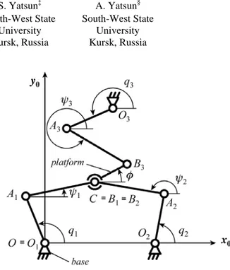
Fig. 1. Kinematic chain of the suggested manipulator.
However, in most of applications, parallel manipulators with less than six degrees of freedom are more useful. These structures can be presented by the following principal groups: (i) 2-DoF translational manipulators [3]–[6]; (ii) planar 3-DoF parallel manipulators [7], [8]; (iii) spherical 3-DoF parallel manipulators [9]–[13]; (iv) 3-DOF translational parallel manipulators [14]–[22]; (v) 3-DOF parallel manipulators with combined translational and rotational motions [23]– [26]; (vi) 4-DOF parallel manipulators for Schoenflies motion [27]–[36]; (vii) 5-DOF parallel manipulators [37]–[39].
Recent reports indicates that the technology of parallel manipulators has not yet made a substantial impacts for the raison that the complicated nonlinearity of parallel manipulators in design and control is not completely accepted by end users [40], [41]. Thus, many basic problems are still opened in order to obtain an efficient exploitation of these structures. One of the drawbacks of the developed parallel structures is also the limited rotation capability. This problem has been studied in [42]–[44] for spatial parallel manipulators but it is not considered for planar parallel manipulators.
The aim of this paper is to propose a new planar 3-DOF manipulator with unlimited rotation capability.
2
II Description of the suggested manipulator
Let us consider the architecture of the suggested manipulator (Fig. 1). It is composed of three legs. Each leg is composed of two rigid links OiAi and AiBi (i = 1, ..,
3). The links OiAi are connected to the base via actuated
revolute joints located at axes Oi and they are defined by
the coordinates qi. The platform of the manipulator is
connected with the links AiBi via revolute joints. The
difference between the traditional planar 3-RRR manipulator and the suggested architecture is the position coincidence of the axes B1 and B2. In this case, we obtain a structure in which the position (x,y) of the centre C of the platform is controlled by a 5R planar manipulator (O1A1CA2O2) and its orientation () by a four-bar linkage (O3A3B3C). Thus, in the presented structure the linear displacements and the orientation are decoupled: the actuators 1 and 2 control the position of the end-effector, and actuator 3 its orientation.
As it is shown in Fig.1 the axis x0 is along of the
vector O1O2. The lengths of the elements OiAi are
denoted as L1i. The lengths of the elements AiBi are
denoted as L2i. The dimension of the platform CB3 is
denoted as R. The positions of the base axes Oi along x0
and y0 axes are denoted as (xOi, yOi), with xO1 = yO1 = yO2
= 0.
Let us consider the geometric models of the manipulator. From the previous description, one can find the loop-closure equations:
i i i i i i
OC OO O A A B B C (1)
from which it comes
1 2 1 2 cos cos sin sin Oi i i i i BiC Oi i i i i BiC x L q L x x y L q L y y (2)
where [xCBi, yCBi]T represents the expression of vector CBi
in the base frame. For i = 1 or 2, [xBiC, yBiC]T = 0, and
[xCB3, yCB3]T = R [cos , sin ]T.
Rearranging (2) and squaring both sides, we obtain the following system:
2
2 2 1 11cos 1 11sin 1 21 0 g xL q yL q L (3a)
2
2 2 2 O2 12cos 2 12sin 2 22 0 g xx L q yL q L (3b)
2 3 3 13 3 2 2 3 13 3 23 cos cos ... sin sin 0 O O g x R x L q y R y L q L (3c)more generically it can be written
2 1 2 2 1 2 cos ... sin 0 i CBi Oi i i CBi Oi i i i g x x x L q y y y L q L (4)III Inverse kinematics
Developing (4) and factorizing with respect to cosine and sine qi, it comes cosai qibisinqi (5) ci 0 where
1 2 i BiC Oi i a xx x L (6a)
1 2 i BiC Oi i b yy y L (6b)
2
2 2 2 1 2 i BiC Oi BiC Oi i i c xx x yy y L L (6c)Using the following relationships 2 2 1 cos 1 i i i t q t , 2 2 sin 1 i i i t q t with tan 2 i i q t (7) (5) becomes
2 2 0 i i i i i i i c a t b t c a (8)Thus, the solutions ti of this polynomial can be found
as 2 2 2 i i i i i i i b b c a t c a (9)
Therefore, for one given position of the end-effector, the inverse geometric model can be found as:
2 2 2 1 2 tan i i i i i i i b b c a q c a (10)
in which the sign ± stands for the two possible working modes of the leg i.
IV Forward kinematics
Due to the decoupling properties of the robot, the forward geometric model of this robot can be solved in two steps: 1. find the expression of x and y as a function of q1 and
q2, using (3a) and (3b);
2. find the expression of as a function of q1, q2 and q3 using (3c).
Developing (3a) and 3b and factorizing with respect to
x and y, it comes 2 2 1 1 1 0 x d xy e yf (11a) 2 2 2 2 2 0 x d xy e yf (11b) where
1
2 cos i Oi i i d x L q (12a) 1 2 sin i i i e L q (12b) 2 2 1 2 i i i f L L (12c)From (11a) and (11b), one can obtain the following relation
2 1 2 1
(d d x) (e e y) (13)
Introducing it into (11a) leads to, for d2d1 : 0
2 1 1 1 0 u y v yw (14) where 2 2 1 ( 2 1) ( 2 1) u d d e e (15a)
1 ( 2 1) 2 1 1 2 v d d d e d e (15b) 2 1 ( 2 1) 1 w d d f (15c) Solving (14) leads to 2 1 1 1 1 1 4 2 v v u w y u (16)in which the sign ± stands for two possible assembly modes of the system composed of legs 1 and 2. Introducing (16) into (13) allows finding the position of the end-effector.
Then, introducing (13) and (16) into (3c) and developing leads to 2cos 2sin 2 0 u v w (17) where
2 2 O3 13cos 3 u R xx L q (18a)
2 2 O3 13sin 3 v R yy L q (18b)
2 2 3 13 3 2 2 2 3 13 3 23 cos ... sin O O w x x L q y y L q L R . (18c)Using the following relationships 2 2 1 cos 1 t t , 2 2 sin 1 t t with t tan 2 (19) (17) becomes
2 2 2 2 2 2 2 0 w u t v tw u (20)Thus, the solutions of this polynomial can be found as
2 2 2 2 2 2 2 2 2 v v w u t w u (21)
Therefore, for one given position of the end-effector, the inverse geometric model can be found as:
2 2 2 2 2 2 2 1 2 2 2 tan v v w u w u (22)
in which the sign ± stands for the two possible assembly modes of the platform.
V Singularity analysis
Differentiating (3a) to (3c) with respect to time leads to the following relation:
At + Bq 0 (23)
where t[ , , ]x y T is the platform twist,
1 2 3
[ ,q q q, ]T
q
the vector of the articular velocities, and A and B two matrices of which expressions are
3 0 0 T T i i i T g g g x y m 1 2 3 r A r r (24a) 11 22 33 0 0 0 0 0 0 i b g b b B q (24b) with [cos , sin ] T T i i i r (25a)
3 sin 3 m R (25b)
1 2sin ii i i b L L q (25c)where ri is the direction of the wrench applied by the leg i
on the platform, and mi its moment.
As a result:
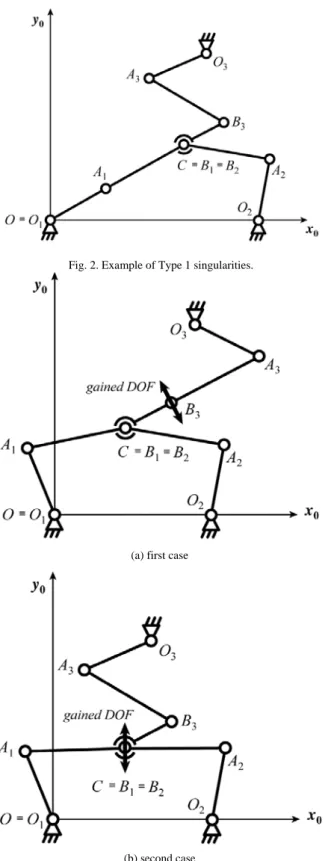
1. the Type 1 singularities appear when bii = 0, for i = 1,
2 or 3; such relation appear when the segments OiAi
and AiCi are located on the same line (Fig. 2)
2. a first case of Type 2 singularities appear when m3 = 0; such relation appear when the segments CB3 and A3B3 are located on the same line (Fig. 3a)
3. a second case of Type 2 singularities appear when r1 is
collinear to r2; such relation appear when the segments
4 Fig. 2. Example of Type 1 singularities.
(a) first case
(b) second case
Fig. 3. Examples of Type 2 singularities.
It known that in the case of high-speed motions, the shaking force and shaking moment bring about variable dynamic loads on the frame and, as result, vibrations.
One of the effective means for reduction of these vibrations is the mass balancing of moving links of manipulators. Therefore in the next section the shaking force and shaking moment balancing of the suggested manipulator is considered
VI Balancing
Let us start by shaking force balancing of the suggested manipulator.
A. Shaking force balancing
In order to achieve the dynamic balancing of the suggested manipulator, we first have to ensure that it is force balanced. For this purpose, the masse of the platform could be substituted by two equivalent point masses located at the axes B3 and C:
3 3 1 1 0 pl pl B pl B S CS C m m L L m (26)
where mB3 is the point mass located on the joint axis B3;
mC is the point mass located on the joint axis C; mpl is the
mass of the moving platform; LB3Spl is the distance of
joint centre B3 from the centre of mass Spl of the platform;
LCSpl is the distance of axe C from the centre of mass Spl
of the platform. This allows for the transformation of the manipulator balancing problem into a problem of balancing legs carrying concentrated masses.
The centre of mass of each leg relative to its base Oi
(Fig. 1) can be found by the expressions [45]:
Si i Si i Si Bi Bi i i Bi x m x m x m x m mm (27)
Si i Si i Si Bi Bi i i Bi y m y m y m y m mm (28) where cosxSiRi qi (29) sinySiRi qi (30) 1 cos ' cos Si i i i i x L q R (31) 1 sin ' sin Si i i i i y L q R (32) i i i i Bi L q L x 1 cos 2 cos (33) i i i i Bi L q L y 1 sin 2 sin (34)mi and m are the masses of links Oi iAi and AiBi; mB1 =
mB2 = 0.5 mC; Ri is the distance of the centre of mass S i
of the link OiAi from the joint centre Oi; R’i is the
distance of the centre of mass S of the link Ai iBi from the
joint centre Ai.
Thus, for the position of centre of mass to remain constant it is sufficient that the coefficients of the variables q and i i be equal to zero, i.e.
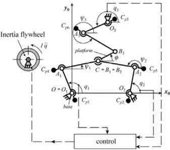
Fig. 4. Shaking moment balancing of fully force-balanced manipulator by an inertia flywheel. 2 ' 0 i i i B i m R m L (35) 1 ( ) 0 i i i i B i m R mm L (36)
The conditions (35) and (36) can be satisfied by adding two counterweights on each leg, which produce negative values of radii R and R . After such a redistribution of masses, the centre of mass of the manipulator remains motionless for any motion of links and hence, the manipulator transmits no inertia loads to its base (Fig. 4).
B. Shaking moment balancing
Now that the inertia force balancing is achieved, we have to consider the cancellation of the shaking moment. For the suggested manipulator, the shaking moment balancing is constructively more efficient by inertia flywheel [45]. Fig. 4 shows the fully force-balanced manipulator and balancing inertia flywheel, which is mounted on the base of the manipulator.
To balance this shaking moment, the inertia flywheel with an axial moment of inertia denoted as I can be used. The angular acceleration of this inertia flywheel driven by a complementary actuator 4 is the following:
qMsh/I (37) It should be mentioned that the axial inertia moment of the flywheel must be selected in such a manner that its rotation with prescribed acceleration will be feasible.
Therefore, the reaction of the balancing inertia flywheel on the frame cancels the shaking moment due to the parallel manipulator. In other words, the actuator,
which moves the balancing inertia flywheel with a prescribed angular acceleration q has a reaction on the frame which is similar but opposite to the
shaking moment of the parallel manipulator. Thus, full shaking moment is annulled. The angular velocity q(t) and angular displacements q(t) can be determined by simple integration of the obtained values of q
t .In order to numerically verify the shaking force and shaking moment balancing of the manipulator an ADAMS model was developed and dynamic simulations were carried out.
For the simulations, the geometric parameters used are of the model are those of the demonstrator that is given in section VII. With regard to mass and inertia parameters the following values have been used:
- m1 = m2 = 0,497 kg, m3 = 0,565 kg, m’1 = m’2 = 0,483 kg, m’3 = 0,620 kg, mpl = 0,210 kg; - I1 = I2 = 1,43.10-3 kg.m², I3 = 2,08.10-3 kg.m², I’1 = I’2 = 1,32.10-3 kg.m², I’3 = 2,73.10-3 kg.m², Ipl = 0,26.10-3 kg.m²; - Ri = 0.5 L1i, R’i = 0.5 L2i, LB3Spl = LCSpl = 0.5 R;
In order to cancel the shaking force the counterweights should be added. Their parameters are given by:
- LOiCpi = 0.5 L1i, LAiCp(i+3) = 0.5 L2i;
- mCp1 = mCp2 = 3.06 kg, mCp3 = 3.68 kg, mCp4 = mCp5 =
0.694 kg, mCp6 = 0.830 kg;
where LOiCpi corresponds to the distance between point Oi
and the counterweights positioned at Cpi and LAiCp(i+3) to
the distance between point Ai and the counterweights
positioned at Cp(i+3) (Fig. 4); mCpi is the mass of the
counterweight located at Cpi.
In Fig. 5 are presented the shaking force and shaking moment before (full black line) and after (dotted black line)balancing. It is observed that, after mass balancing, the shaking force is cancelled while the shaking moment increases. In order to balance the shaking moment, an optimal trajectory planning is introduced into the control of the inertia flywheel using eq. (37). Taking into account that the axial moment of inertia of the flywheel is equal to 0.02 kg.m², its optimal displacement is presented at Fig. 6. After the use of this optimal planning, the shaking moment is also cancelled (Fig. 7c, grey full line).
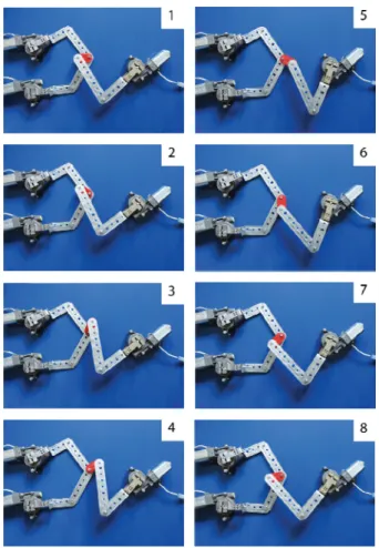
VII Demonstrator
In order to better illustrate the proposed concept, a driven demonstrator has been built. The parameters of the manipulator are the following: L11 = L12 = 155 mm, L21 =
L22 = 150 mm, L13 = 180 mm, L23 = 200 mm, R = 50 mm,
O1 = (0, 0)mm, O2 = (180, 0)mm and O3 = (80, 420)mm. Fig. 7 shows the motions generated by this driven demonstrator which is a first model of the suggested manipulator. Its theoretical workspace is presented at Fig. 8. It can be computed geometrically as the intersections of six portions of circles described by [2]:
6 (a)
(b)
(c)
Fig. 5. Shaking force before (full black line) and after (dotted black line) mass redistribution and shaking moment before (black lines)
and after (grey line) balancing by the inertia flywheel. - two circles C1 and C4 centred in O1, of respective radii
equal to L11 + L21 and L11 – L21; these circles represent the extreme displacements of the robot leg 1;
- two circles C2 and C5 centred in O2, of respective radii equal to L12 + L22 and L12 – L22; these circles represent the extreme displacements of the robot leg 2;
Fig. 6. Definition of the optimal angular displacement for the inertia flywheel.
Fig. 7. Motion generation via a driven demonstrator built in the South-West State University of Kursk.
- two circles C3 and C6, centred in O3, of radius equal to
L13 + L23 – R and L13 – L23 + R; these circle represents the extreme displacements of the robot end-effector linked to leg 3 for any platform orientation;
Fig. 8. Maximal reachable workspace of the robot (to scale). As 5R robots have the ability to cross the Type 1 singular configurations [46], it can be shown that any of the workspace points can be attained without crossing of the Type 2 singular configurations presented at Fig. 3b, that are due to the 5R positioning architecture. It should also be mentioned that the Type 2 singularities presented at Fig. 3a, that appear for some specific platform orientations, can be crossed using optimal motion generation [47].
Taking into account these considerations, it is possible to define the maximal regular workspaces of the robot, for any platform orientation [48], [49]. It is proposed here to characterize the size of two different maximal regular workspaces: a circle and a square. Using some CAD software [50], it can be shown that, for this driven demonstrator:
- the maximal inscribed circle is centred in (90, 64.5) mm and has a radius of 105.75 mm
- the maximal inscribed square is centred in (90, 85) mm and has a edge length of 170 mm.
Finally, it should be noted that for dynamic tests a prototype will be developed with prescribed mass/inertia parameters and optimized control system.
VIII Conclusion
In this paper, the development of a new 3-DoF planar parallel manipulator with unlimited rotation capability was addressed. The advantage of the proposed design concept is the high rotational capability, which can be useful for many industrial applications: in automated assembly systems, cutting machines, simulators, micro-motion manipulators. This is a first publication, in which structural and kinematic properties were disclosed, as well as the shaking force and moment balancing. The linear displacements and orientation of the platform is
illustrated via a driven demonstrator, which is a first driven model of the manipulator.
Dynamic simulations, optimization and tests, that can perform this design concept will be a next step of this project.
Acknowledgments
This research was supported by a grant from Russian National Agency of Innovation.
References
[1] Dasgupta, B and Mruthyunjaya, T.S. The Stewart platform manipulator: a review. Mechanism and Machine Theory, 35(1):15–40, 2000.
[2] Merlet, J.-P. Parallel Robots. Springer, 432p., 2006.
[3] Gao, F. et al. Performance evaluation of two degrees of freedom parallel robots. Mechanism and Machine Theory, 33(2):661–668, 1998.
[4] Huang, T. et al. Conceptual design and dimensional synthesis of a novel 2-DoF translational parallel robot for pick-and place operations. ASME Journal of Mechanical Design, 126(3):449–455, 2004.
[5] Wu, J. S. et al. Analysis and application of a 2-DOF planar parallel mechanism, ASME Journal of Mechanical Design, 129(4):434– 437, 2007.
[6] Da Silva, M. M. et al. Integrating structural and input design of a 2-DOF high-speed parallel manipulator: a flexible model-based approach. Mechanism and Machine Theory, 45(11):1509-1519, 2010.
[7] Gosselin, C.M. and Angeles, J. The optimum kinematic design of a planar tree-degrees-of-freedom parallel manipulator. ASME Journal of Mechanical Design, 110(1):35–41, 1988.
[8] Foucault, S. and Gosselin, C. M. Synthesis, design and prototyping of a tree-of-freedom reactionless parallel manipulator. ASME Journal of Mechanical Design, 126(6):992–999, 2004. [9] Gosselin, C.M. and Angetes, J. The optimum kinematic design of a
spherical three-degree-of-freedom parallel Manipulator, ASME Journal of Mechanical Design, 111(2):202–207, 1989.
[10] Gosselin, C. M. and Lavoie, E. On the kinemaric design of spherical three degree-of-freedom parallel manipulators, International Journal of Robotics Research. l2(4): 394–402, 1993. [11] Gosselin, C. M., Sefrioui, J., and Richard, M. J. On the direct
kinematics of spherical three-degree-of-freedom parallel manipulators of general architecture. ASME Journal of Mechanical Design, 116(2): 594–598, 1994.
[12] Vischer, P. and Claver, R. Argos: a novel 3-DOF parallel wrist mechanism. International Journal of Robotics Research. 19(1): 5– 11, 2000.
[13] Karouia, A. and Hervé, J.M. A three-DOF tripod for generating spherical rotation. Advances in Robot Kinematics, Lenarcic J. and Stanisic M., Eds. Kluwer Academic Publishers, pages 395–402, 2000.
[14] Clavel, R. Delta, a fast robot with parallel geometry. In proceedings of the 18th International Symposium on Industrial Robot, Lausanne, 26–28 April 1988, pages 91–100, 1988. [15] Tsai, L.-W. Kinematics of a three-dof platform with three
extensible limbs, in: J. Lenarcic, V. Parenti-Castelli, (Eds.). Recent Advances in Robot Kinematics, Kluwer, pages 401–410, 1996. [16] Hervé, J.M. Group mathematics and parallel link mechanisms. In
IMACS/SICE Int. Symp. on Robotics, Mechatronics, and Manufacturing Systems, Kobe, 16–20 September 1992, pages 459–464 , 1992.
[17] Ceccarelli, M. A new 3-DOF spatial parallel mechanism. Mechanism and Machine Theory, 32(8): 895–902, 1997.
8 [18] Carricato, M and Parenti-Castelli, V. A family of 3-DOF
translational parallel manipulators. ASME Journal of Mechanical Design, 125(2): 302-307, 2003.
[19] Kim, D. and Chung, W.K. Kinematic condition analysis of three-DOF pure translational parallel manipulators. ASME Journal of Mechanical Design, 125(2): 323–331, 2003.
[20] Kong, X. and Gosselin, C.M. A class of 3-DOF translational parallel manipulator with linear input–output equations. In Workshop on Fundamental Issues and Future Research for Parallel Mechanisms and Manipulators, Quebec City, Quebec, Canada, 2002, pages 25–32, 2002.
[21] Gosselin, C.M., Kong, X., Foucault, S. and Bonev, I.A. A fully decoupled 3-DOF translational parallel mechanism. In PKM International Conference, Chemnitz, Germany, 2004, pages 595– 610, 2004.
[22] Caro S., Wenger P., Bennis F. and Chablat D. Sensitivity Analysis of the Orthoglide, a 3-DOF Translational Parallel Kinematic Machine. ASME Journal of Mechanical Design, 128(2): 392–402, 2006.
[23] Lee, K.M. and Shah, D. Kinematic analysis of a three-degrees-of-freedom in-parallel actuated manipulator. IEEE Journal of Robotics and Automation, 4(3):354–360, 1988.
[24] Dunlop, G.R. and Jones, T.P. Position analysis of a 3-DOF parallel manipulator, Mechanism and Machine Theory, 32(8):903–920, 1997.
[25] Carretero, J. et al. Kinematic analysis and optimization of an three degree-of-freedom spatial planar manipulator. ASME Journal of Mechanical Design, 122(1): 17–24, 2000.
[26] Jin, Q. and Yang, T.L. Synthesis and analysis of a group of 3-degree-of-freedom partially decouped parallel manipulators. ASME Journal of Mechanical Design, 126(2): 301–306, 2004. [27] Rolland, L. The Manta and the Kanuk: Novel 4-DOF Parallel
Manipulators for Industrial Handling. In ASME IMECE’99 Conference, Nashville, USA, November, pages 831–844, 1999. [28] Pierrot, F., Marquet, F., Company, O., and Gil., T. H4 Parallel
Robot: Modeling, Design and Preliminary Experiments. In IEEE International Conference on Robotics and Automation, Soul, Korea, pages 3256–3261, 2001.
[29] Angeles, J., Morozov, A., and Navarro, O. A Novel Manipulator Architecture for the Production of SCARA motions. in IEEE International Conference on Robotics and Automation, San Francisco, CA, pages 2370–2375, 2000.
[30] Angeles, J., and Morozov, A., 2005. Four-degree-of-freedom parallel manipulator for producing schonflies motions. Patent US2005262959, December 1, 2005.
[31] Angeles, J. The Morphology Design for a Parallel Schönflies-Motion Generator. In Proceedings of the Second International Colloquium on Robotic Systems for Handling and Assembly, Braunschweig, Germany, pages 37–56, 2005.
[32] Yang, T. L., Jin, Q., Liu, A. X., Yao, F. H., and Luo, Y. Structure Synthesis of 4-DOF (3-Translation and 1-Rotation) Parallel Robot Mechanisms Based on the Units of Single-Opened-Chain. In ASME Design Engineering Technical Conference, Pittsburgh, PA, Paper No. DETC2001/DAC-21152, 2001.
[33] Li, Q. C. and Huang, Z. Type Synthesis of 4-DOF Parallel Manipulators. In IEEE International Conference on Robotics and Automation, Taipei, Taiwan, pages 755–760, 2003.
[34] Carricato, M. Fully Isotropic Four-Degrees-of-Freedom Parallel Mechanisms for Schoenflies Motion. International Journal of Robotics Research. 24(5): 397–414, 2005.
[35] Gogu., G. Singularity-Free Fully-Isotropic Parallel Manipulators with Schönflies Motions. In International Conference on Advanced Robotics, July 18-20, pages 194-201, 2005.
[36] Richard, P.L., Gosselin, C., and Kong, X. Kinematic Analysis and Prototyping of a Partially Decoupled 4-DOF 3T1R Parallel Manipualtor. ASME Journal of Mechanical Design. 129(6):611– 616, 2007.
[37] Jin, Q. et al. Structure synthesis of a class of five-DOF parallel robot mechanisms based on single-open-chain units. In ASME Design Engineering Technical Conference Pittsburgh, PA, Paper No. DETC2001/DAC-21153, 2001.
[38] Chablat, D. and Wenger, Ph. Device for the movement and orientation of an object in space and use thereof in rapid machining. European patent EP1597017, November 23rd, 2005.
[39] Briot, S., Arakelian, V. and Guégan S. PAMINSA: A new family of partially decoupled parallel. Mechanism and Machine Theory, 44(2): 425-444, 2009.
[40] Merlet, J.P. An initiative for the kinematic study of parallel manipulators. Workshop on Fundamental Issues and Future Research Directions for Parallel Mechanisms and Manipulators, Québec, Canada, October 3-4, 2002.
[41] Brogårdh, T. PKM Research - Important issues, as seen from a product development perspective at ABB Robotics", Workshop on Fundamental Issues and Future Research Directions for Parallel Mechanisms and Manipulators, Québec, Canada October 3-4, 2002.
[42] Liu X.-J., Wang J. and Pritschow G. A new family of spatial 3-DOF fully-parallel manipulators with high rotational capability. Mechanism and Machine Theory, 40(4): 475–494, 2005. [43] Company O et al. Schoenflies motion generation: A new non
redundant parallel manipulator with unlimited rotation capability. In IEEE International Conference on Robotics and Automation, Barcelona, Spain, pages 3261–3266, 2005.
[44] Nabat, V. Parallel robot with articulated platforms: from concept to industrial solution for pick-and-place operations. PhD dissertation, Montpellier, 138p. 2007.
[45] Arakelian, V and Smith, M. R. Design of planar 3-DOF 3-RRR reactionless parallel manipulators. Mechatronics, 18(10): 601–606 2008.
[46] Campos, L., Bourbonnais, F., Bonev, I.A., and Bigras, P. Development of a five-bar parallel robot with large workspace. ASME 2010 International Design Engineering Technical Conferences (IDETC 2010), Montreal, QC, Canada, 2010.
[47] Briot, S. and Arakelian, V. Optimal force generation of parallel manipulators for passing through the singular positions. The International Journal of Robotics Research, 27(8):967–983, 2008. [48] Ur-rehman R., Caro S., Chablat D., Wenger P. Multiobjective path
placement optimization of parallel kinematics machines based on energy consumption, shaking forces and maximum actuators torques: application to the Orthoglide, Mechanism and Machine Theory, 45(8): 1125–1141, 2010.
[49] Chablat, D., and Wenger, P. The kinematic analysis of a symmetrical three-degree-of-freedom planar parallel manipulator. CISM-IFToMM Symposium on Robot Design, Dynamics and Control, Montreal, Canada, June 2004.
[50] Bonev, I.A., and Ryu, J. A Geometrical method for computing the constant-orientation workspace of 6-PRRS parallel manipulators, Mechanism and Machine Theory, 36(1): 1–13, 2001.