HAL Id: tel-02395284
https://tel.archives-ouvertes.fr/tel-02395284
Submitted on 5 Dec 2019
HAL is a multi-disciplinary open access archive for the deposit and dissemination of sci-entific research documents, whether they are pub-lished or not. The documents may come from teaching and research institutions in France or abroad, or from public or private research centers.
L’archive ouverte pluridisciplinaire HAL, est destinée au dépôt et à la diffusion de documents scientifiques de niveau recherche, publiés ou non, émanant des établissements d’enseignement et de recherche français ou étrangers, des laboratoires publics ou privés.
in-situ and laboratory experiments
Andreea-Roxana Vasilescu
To cite this version:
Andreea-Roxana Vasilescu. Design and execution of energy piles : Validation by in-situ and laboratory experiments. Civil Engineering. École centrale de Nantes, 2019. English. �NNT : 2019ECDN0015�. �tel-02395284�
T
HESE DE DOCTORAT DE
L'ÉCOLE
CENTRALE
DE
NANTES
COMUE UNIVERSITE BRETAGNE LOIRE
ECOLE DOCTORALE N°602
Sciences pour l'Ingénieur
Spécialité : Génie Civil
DESIGN AND EXECUTION OF ENERGY PILES
VALIDATION BY IN-SITU AND LABORATORY TESTS
Thèse présentée et soutenue à Nantes, le 08-07-2019
Unité de recherche : Institut de Recherche en Génie Civil et Mécanique
Par
Andreea-Roxana VASILESCU
Rapporteurs avant soutenance :
Pierre Breul Professeur des Universités, Université Clermont Auvergne Frédéric Collin Professeur des Universités, Université de Liège
Composition du Jury :
Président : Jean-Michel PEREIRA Professeur des Universités, Ecole des Ponts Paris Tech Examinateurs : Pierre BREUL Professeur des Universités, Université Clermont Auvergne
Frédéric COLLIN Professeur des Universités, Université de Liège Alice DI DONNA Maître de Conférences, Université Grenoble Alpes Jean-Michel PEREIRA Professeur des Universités, Ecole des Ponts Paris Tech Dir. de thèse : Panagiotis KOTRONIS Professeur des Universités, Ecole Centrale de Nantes Encadrants: Christophe DANO Maître de Conférences, Université Grenoble Alpes
I am using this opportunity to express my gratitude to everyone who supported me throughout the course of this PhD project. It has not been an easy ride and I am thankful for all their aspiring guidance, invaluable suggestions, and friendly advice.
I would like to thank Richard Manirakiza and PINTO for funding this PhD thesis and trusting me with the opportunity to be part of this research project, for encouraging me and teaching me to take responsibility and to never give up.
I would like to express my sincere gratitude to my advisor Prof. Panagiotis Kotronis for the continuous support of my Ph.D study, for his patience, motivation, and inspiring guidance. I am also deeply grateful to my co-supervisors Dr. Christophe Dano and Dr. Anne-Laure Fachille for guiding me through the experimental work, for their valuable insight and suggestions. I am particularly grateful for the assistance given by Dr. Anne-Laure Fauchille through the final part of my experimental campaign and all throughout the thesis-writing period, without whose help this manuscript would have never seen the light of day.
My special thanks are extended to Philippe Gotteland and the FNTP for helping and providing a part of the funding for this work.
My sincere thanks also go to the ENPC and IFSTTAR Paris teams and especially to Prof. Anh Minh Tang and to Dr. Fabien Szymkiewicz for bearing with me during the different experimental campaigns performed together on their site. Without their expertise, constant support and understanding a big part of the experimental work would definitely not have been possible.
I would like to thank M’Hammed Elmejahed from CEREMA for his patient assistance in dealing with the instrumentation system at Sept Sorts as well as for all his friendly advice.
I am particularly grateful to all of my friends and family for encouraging me and supporting my efforts that have been instrumental in the successful completion of this project.
And finally, last but by no means least, my loving thanks to Alexandru Andoniu for putting up with me and for being there for me through thick and thin all through this exciting but challenging project.
Les pieux énergétiques représentent une solution alternative intéressante, face à l’accroissement des besoins mondiaux en énergie et à la réduction de l’utilisation des énergies fossiles. Les pieux géothermiques sont des fondations profondes à double fonction: elles reprennent les charges de la structure et sont des échangeurs thermiques (Brandl 2006). La température du sol est généralement constante au cours de l'année pour des profondeurs supérieures à 5m (Williams & Gold Veuillez 1977) et se situe autour de 13°C en France. Pour profiter de cette énergie contenue dans le sol, les pieux sont équipés d’un système de tubes dans lequel la circulation (en circuit fermé) d’un fluide caloporteur permet l’échange thermique entre les pieux et le sol afin de chauffer ou refroidir le bâtiment selon la saison. Au fil des saisons, ces pieux sont soumis à des cycles de chauffage et de refroidissement entraînant respectivement des cycles de dilatation et de contraction, qui participent à l’augmentation de déplacements verticaux et la modification de la contrainte verticale dans les pieux, de la résistance du sol ou de manière plus générale à des modifications du comportement thermomécanique du sol. Cependant, malgré le nombre croissant des études sur les pieux géothermiques ces dernières années, l’impact de cycles thermomécaniques sur le comportement du sol et de l’interface sol-pieu sont encore mal documentés.
L’objectif principal de la thèse est d’identifier et de quantifier les principaux facteurs influençant le dimensionnement des pieux géothermiques, qui sont impactés par les changements de température des pieux lors de leur activité. Pour ce faire, ce travail de thèse a été dressé en 3 campagnes expérimentales, dont deux à échelle réelle : (i) une première campagne à chargement thermomécanique contrôlé (Marne La Vallée), (ii) une seconde campagne en conditions d’utilisation réelles sous une station d’épuration (Sept Sorts) et (iii) une troisième campagne à l’échelle du laboratoire grâce à une nouvelle machine de cisaillement direct d’interface permettant l’étude du comportement thermo mécanique des interfaces sol-structure. Ces trois campagnes expérimentales ont pour but de quantifier l’effet de la température et des cycles de température sur le comportement des pieux énergétiques. Les premiers résultats expérimentaux de la campagne de Sept Sorts ont ensuite été simules dans le code LAGAMINE via la méthode des éléments finis, afin d’adopter une approche complémentaire permettant de mieux appréhender la réponse thermomécanique de ce type de pieu lors de l’activation géothermique.
The global energy demand as well as the socio-economical stakes concerning the increase of energy costs due to fossil fuels has stimulated the research for new sustainable and cost effective energy sources. Energy piles, also called thermo-active piles, are an alternative solution for heating and/or cooling needs. Energy piles are double purpose structures that allow transferring the loads from the superstructure to the soil and that integrate pipe circuits allowing heat exchange between the pile and the surrounding ground. It is due to the fact that below 5m deep, the soil temperature, around 13°C in France, remains constant throughout the year, hence the soil can be used as a source of heat during winter and conversely as a heat sink during summer. During the operation of the ground source system energy piles undergo cyclic temperature changes that can have an impact on the pile mechanical behaviour as well as on the soil-pile interface. Although this solution has been used for some time and an increasing number of research results are available on this topic, the information concerning the long term behaviour of the foundation and of the surrounding soil is still limited.
The objective of this thesis is to identify and quantify the principal parameters involved in the geotechnical design of pile foundations impacted by temperature changes associated with geothermal activation. For this purpose, this research work was organised in 3 experimental campaigns: (i) A full scale load controlled test at Ecole des Ponts Paris-Tech, (ii) Full scale energy piles monitoring under real exploitation conditions at Sept Sorts, (Seine et Marne, France), (iii) Laboratory tests in order to assess the effect of temperature and temperature cycles at the soil-pile interface. The experimental results are used to estimate the effect of geothermal activation of a pile foundation, on its bearing capacity as well as on its long-term exploitation. Finally, preliminary numerical simulations were performed using a thermo-hydro mechanical model, using the finite element method code LAGAMINE able to capture the main phenomena.
CONTENTS
INTRODUCTION ... 13
RESEARCH OBJECTIVES ... 15
RESEARCH OUTLINE ... 15
1. ENERGY PILES OVERVIEW ... 17
1.1PRINCIPLES OF GEOTHERMAL UTILIZATION OF FOUNDATIONS ... 17
1.2PHYSICAL PROCESSES INVOLVED IN THE EXPLOITATION OF ENERGY PILES ... 19
1.2.1 Heat transfer in soil ... 19
1.2.2 Heat transfer in concrete energy piles ... 23
1.3GEOTECHNICAL CHALLENGES INVOLVED IN THE EXPLOITATION OF ENERGY PILES . 25 1.3.1 Temperature induced changes in soil ... 25
1.3.2 Temperature induced changes in the pile ... 26
1.4DESIGN AND EXECUTION OF ENERGY PILES ... 28
1.4.1 Short pile foundations overview ... 28
1.4.2 Energy piles design ... 30
2. IN SITU STUDY OF THERMOMECHANICAL BEHAVIOUR OF ENERGY PILES ... 37
2.1INTRODUCTION ... 37
2.2BACKGROUND ... 38
2.3ECOLE DES PONTS PARIS TECH CASE STUDY: CONTROLLED LOADING CONDITIONS 41 2.3.1 Project overview ... 41
2.3.2 Field test details ... 42
2.3.3 Results ... 47
2.3.4 Discussion ... 55
2.3.5 Conclusions ... 56
2.4SEPT SORTS CASE STUDY: GEOTHERMAL EXPLOITATION CONDITIONS ... 57
2.4.1 Project overview ... 57
2.4.2 Field test details ... 57
2.4.3 Results ... 66
SOIL-PILE INTERFACE ... 85
3.1BACKGROUND ... 85
3.2MATERIALS ... 90
3.2.1 The concrete plate ... 90
3.2.2 The NE34 Fontainebleau sand ... 92
3.2.3 The Carbonate sand ... 93
3.2.4 The Green Clay ... 94
3.3 EXPERIMENT CAMPAIGNS ON A NEW INTERFACE DIRECT SHEAR DEVICE ADAPTED FOR THERMO-MECHANICAL LOADING ... 95
3.3.1 Description of the experimental device ... 95
3.3.2 Sample preparation ... 97
3.3.3 Experimental program ... 98
3.4RESULTS ... 103
3.4.1 Validation campaign ... 103
3.4.2 Thermo-mechanical behavior of Fontainebleau sand – concrete interface subjected to monotonic and cyclic thermal loading ... 104
3.4.3 Thermo-mechanical behavior of the carbonate – concrete interface subjected to cyclic thermal loading ... 113
3.5GENERAL DISCUSSION AND CONCLUSIONS ... 120
4. NUMERICAL MODELLING OF ENERGY PILES ... 123
4.1INTRODUCTION ... 123
4.2MATHEMATICAL FORMULATION ... 123
4.3CONSTITUTIVE MODEL ... 125
4.4NUMERICAL MODEL FOR ENERGY PILES IN SATURATED SAND - CENTRIFUGE TESTS ... 127
4.4.1 Centrifuge modelling of energy foundations ... 127
4.4.2 Centrifuge model ... 128
4.4.3 Axisymmetric finite element model ... 129
4.4.4 Results and discussion ... 131
4.5NUMERICAL MODEL FOR ENERGY PILES IN EXPLOITATION CONDITIONS -SEPT SORTS PILE... 134
4.5.1 Axisymmetric finite element model ... 134
4.5.2 Results and discussion ... 136
5.1EXPERIMENTAL OUTCOMES ... 140
5.1.1 Ecole des Ponts Paris Tech case study: controlled loading conditions ... 140
5.1.2 Sept Sorts case study: geothermal exploitation conditions ... 141
5.1.3 Laboratory study of the effect of temperature on the pile-soil interface ... 142
5.1.4 Numerical outcomes ... 142
I
NTRODUCTION
The global aim to reduce greenhouse gas emission to avoid the energy dependence on fossil fuels and the new building energy requirements have urged the search for new environmentally friendly energy sources worldwide. Directive 2001/77/EC laid down a framework for encouraging energy production from renewable energy sources in the European Union. This framework was further reinforced by Directive 2009/28/EC which requires member states to establish mandatory national targets consistent with the EU strategy. In the case of France it was set that by 2020, 23% of the energy consumed should come from renewable energy sources. This percentage should further increase to 32% by 2030.
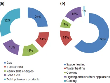
According to the European Environment Agency, the building sector (residential and tertiary buildings) accounted for about 25.71% of the end-use energy consumption in 2016. Moreover, heating represents the source of an average of 69.1% of the energy consumption of French homes. Similar values of the energy use can be found in other countries with comparable climate, while in cold climate countries, building heating can account for more than 80% of the entire energy consumption in the residential and tertiary sector (Figure 0-1 a, b).
Figure 0-1 Energy consumption in Europe, according to the European Environment Agency (a) by energy vector, (b) by sector.
Furthermore, energy consumption in European buildings is responsible for around 25% of the total CO2 emissions (Connolly et al. 2012). In order to address target reductions for low-carbon economies, new buildings must comply strict requirements on energy efficiency, such as the Directive 2010/31/EU regarding ‘Nearly zero-energy Building (NZEB)’. Geothermal District Heating is considered a key technology to decarbonise the heat sector and reduce Europe’s dependency from fossil fuels. This approach is based on the use of geothermal energy to provide heat through a distribution network. Current installed capacity is 4,400 MWth and it is forecasted that it will grow to 6,500 MWth in 2018 (EGEC 2011).
To comply with NZEB regulations, the use of shallow geothermal heat (i.e. those using the thermal energy from depths up to 100 m) for heating and cooling of buildings has experimented lastly an expansion. Energy geostructures such as energy piles represent the next generation of ground heat exchangers for geothermal heat pumps. Energy pile foundations are double purpose structures as they are used for transferring loads from the structure to the ground and as energy production systems due to the fact that they are equipped with polyethylene pipes (the heat exchange system) through which a heat carrier fluid is circulated (Figure 0-2).
Figure 0-2 Energy piles structure.
The system, connected to a heat pump, extracts thermal energy for heating or injects it into the ground for cooling purpose. A single energy pile may deliver on average between 25-50W/m (SIA 2005) depending on its size, construction details, soil stratification or how it is operated.
However, despite the promising capabilities, the deployment of energy piles has been hindered by several factors such as: (i) insufficient information on the pile response to pile cyclic thermal loading, (ii) lack of reliable data on the long-time behaviour of energy foundations, (iii) high installation costs due to non-standardized procedures.
Research objectives
This PhD thesis resulted as the collaboration between PINTO, the French National Federation of Public Works (FNTP) and Centrale Nantes (thèse CIFRE) and presents a framework for understanding the factors participating in the energy piles design and execution. The main goal of this work is to improve the understanding of the thermo-mechanical behavior of energy piles, hence the main objectives set are:
Objective 1: Identify the physical processes and geotechnical challenges involved in the geothermal activation of pile foundations
Objective 2: Qualitative and quantitative characterization of the impact of geothermal activation of pile foundation through a proof of concept : in-situ tests
Objective 3: Evaluation of the effect of temperature and temperaure cycles at the pile-soil interface
Objective 4: Numerical simulations of energy piles
Research outline
The present work is organized in 5 chapters as follows:
Chapter 1 presents an introduction to the concept of energy piles. This chapter is meant to underline the physical processes and geotechnical challenges involved in the exploitation of energy piles and to identify the different factors involved in the design and execution of energy piles. The literature overview of the state of the art for energy piles is presented for each subsequent chapter.
Chapter 2 focusses on the in-situ behavior of energy piles by presenting the results of two full scale experimental campaigns. After assessing the state of the art, the experimental setup and the results of a first experimental campaign, designed in an academic setting is presented. An energy pile, first loaded to its estimated serviceability limit state was subjected to several heating-cooling cycles over the period of 6 weeks. The pile was then loaded to failure in order to determine the effect of temperature cycles
long-term behavior of an energy foundation under exploitation conditions. Three piles (two energy piles and a conventional pile) were instrumented during the construction of a new building in a water treatment plant. The energy foundation made out of 100 piles, out of which, 45 energy piles, was designed to cover 100% of the heating and cooling needs of the nearby 340 m2 office building. Seasonal variations in ground temperature and axial strain change were recorded for a year prior to the operation of the ground source heat pump system, and more than one year after the foundation’s geothermal activation.
Chapter 3 investigates the thermomechanical behavior of the soil-structure interface in the laboratory. A new advanced interface direct shear test device was used in order to evaluate the effect of temperature and temperature cycles at the soil-structure interface. The device was first validated and then employed for of a series of tests using the most commonly encountered sand types (silica sand and carbonate sand).
Chapter 4 is related to the numerical simulation of energy piles. Thermo-hydro-mechanical simulations of a reduced scale experiment (controlled material and loading conditions) are first presented in order to validate the chosen simulation strategy, and then numerical simulations of a real case study are detailed.
Chapter 5 presents the summary of the work, the main results, conclusions and recommendations for further research.
1.
E
NERGY PILES OVERVIEW
1.1 Principles of geothermal utilization of foundations
According to the definition given in the Directive 2009/28/EC of the European Parliament, “geothermal energy is the energy stored in the form of heat beneath the surface of the solid Earth”. In other words: geothermal energy is the natural heat contained within the Earth. Part of this enormous amount of heat (contained in water or steam transported to the surface) can be extracted and used for various purposes, i.e. to generate electricity, or directly for many applications (GEOCOM 2015) such as energy geostructures.
Figure 1-1 Principle of geothermal activation of pile foundations: (a) Heat is extracted from the ground during the cold seasons in order to heat the building, (b) Ground temperature evolution, (c)
Heat is injected into the ground during the warm seasons in order to cool the building.
Energy geostructures are systems that couple their load bearing role with the ground heat exchange and are designed to operate within the shallow surface of the Earth (depth < 100m) which is in thermal equilibrium with the atmosphere (Figure 0-1). At this depth the undisturbed soil temperature is close to the annual average air temperature, which depends on the site. Heat can be extracted from the ground at a relatively low temperature (the average undisturbed soil temperature in France is equal to 13°C, Figure 1-1), that is then increased through a heat pump and used in a heating
operate the system, i.e. the seasonal performance factor amounts to 3.3 – 4.5 (Sanner et al. 2001). For cooling, the system can be reversed, and the heat from the building can be injected into the ground (Figure 1-1).
Heat pumps are a form of heat engine that uses mechanical work to transfer heat from a low temperature source to a higher temperature sink. Although various forms of thermodynamic cycle can be used to move heat between source and sink, the predominant form is based on the vapour compression cycle in which a refrigerant gas is evaporated, compressed, and condensed in turn to transfer heat. A schematic representation of the principle of functioning of a heat pump is presented in Figure 1-2 a et b. The prime reason for the interest in using heat pumps to provide heating and cooling is that it takes less work to move heat from source to sink than it does to convert primary energy into heat. In other words, the power required is noticeably less than the heating or cooling delivered. This effect is quantified in classical thermodynamics by the coefficient of performance (COP Eq. 1-1).
Figure 1-2 (a) Conceptual model of a heat pump, (b) an idealized cycle represented on an enthalpy-pressure diagram (Rees 2016).
𝑪𝑶𝑷 =𝒆𝒏𝒆𝒓𝒈𝒚 𝒐𝒖𝒕𝒑𝒖𝒕 𝒂𝒇𝒕𝒆𝒓 𝒉𝒆𝒂𝒕 𝒑𝒖𝒎𝒑[𝒌𝑾]
𝒆𝒏𝒆𝒓𝒈𝒚 𝒊𝒏𝒑𝒖𝒕 𝒇𝒐𝒓 𝒐𝒑𝒆𝒓𝒂𝒕𝒊𝒐𝒏[𝒌𝑾] Eq. 1-1
For economic reasons the required value of COP should be ≥4 (Brandl 2006). This means that at least 75% of the energy should come from the ground. The COP can be different between summer and winter. For example the winter operation COP may vary
between 3 and 5 while the summer COP may vary between 2.5 and 3.5 (Brandl 2006). The efficiency of the heat pump is strongly influenced by the difference between the extracted and the used temperature. A high user temperature and a low extraction temperature in the heat exchanger, reduces the system’s efficiency (Figure 1-2 b). This
means that the usable temperature in the secondary circuit should not be higher than 35-40°C and the extraction temperature in the primary circuit should not be lower than 5°C.
Another parameter useful in the evaluation of the performance of ground source heat pumps system is the seasonal performance factor (SPF, Eq. 1-2). This is not useful for rating equipment but is more useful when making comparisons with other technologies or making realistic estimates of running costs or carbon emission savings. It is defined as the ratio of the usable energy output to the energy input required to obtain it. Therefore SPF includes not only the heat pump but also the other energy consuming elements (the circulation pump). Common values for SPF may vary between 3.8 and 4.3 (Brandl 2006; Yavari et al. 2016b).
𝑺𝑷𝑭 =𝒖𝒔𝒂𝒃𝒍𝒆 𝒆𝒏𝒆𝒓𝒈𝒚 𝒐𝒖𝒕𝒑𝒖𝒕 𝒐𝒇 𝒕𝒉𝒆 𝒆𝒏𝒆𝒓𝒈𝒚 𝒔𝒚𝒔𝒕𝒆𝒎[𝒌𝑾]
𝒆𝒏𝒆𝒓𝒈𝒚 𝒊𝒏𝒑𝒖𝒕 𝒐𝒇 𝒕𝒉𝒆 𝒆𝒏𝒆𝒓𝒈𝒚 𝒔𝒚𝒔𝒕𝒆𝒎[𝒌𝑾] Eq. 1-2
Experience has shown that systems using ground source heat pumps (GSHP) may save up to two thirds of conventional heating costs. Moreover they represent an effective contribution to environmental protection by providing clean renewable energy.
1.2 Physical processes involved in the exploitation of energy piles
1.2.1 Heat transfer in soil
The soil is a multiphase material with a complex heat transfer mechanism involving conduction, convection, radiation, vaporization and condensation, ion exchange and freezing-thawing process.
As suggested in Figure 1-3 the main heat transfer mechanism in soil is conduction, followed by convection. Heat conduction is also possible if there is a phase change of water (latent heat during vaporization and condensation). Radiation only bares minimum importance (1%) and is restricted to the upper soil layers and freezing-thawing, even though may help transfer heat more efficiently, is to be avoided for thermoactive foundations due to geotechnical reasons.
The total heat transfer, 𝑞𝑡𝑜𝑡 (Eq. 1-3), may be defined as (Rees et al. 2000):
𝒒𝒕𝒐𝒕= 𝒒𝒄𝒐𝒏𝒅+ 𝒒𝒍,𝒄𝒐𝒏𝒗+ 𝒒𝒗,𝒄𝒐𝒏𝒗+ 𝒒𝒍𝒂𝒕 Eq. 1-3
where 𝒒𝒄𝒐𝒏𝒅 represents heat transfer by heat conduction, 𝒒𝒍,𝒄𝒐𝒏𝒗 represents heat transfer
by liquid convection, 𝒒𝒗,𝒄𝒐𝒏𝒗 represents heat transfer by vapour convection and 𝑞𝑙𝑎𝑡
represent the latent heat transfer.
the soil pores. It increases with decreasing water content and it can be expressed as follows:
𝒒𝒍𝒂𝒕= 𝑳𝟎𝝆𝒍𝝊𝒗 Eq. 1-4
where 𝐋𝟎 is the latent vaporisation heat, 𝛒𝐥 is the density of water and 𝒗𝒗 is the vapour
velocity.
Figure 1-3 Predominant heat transfer mechanism in soil depending on the degree of saturation and grain size (after Farouki 1981 and Loveridge 2012).
Heat convection occurs between thermo-dynamic systems that move relative to each other. In soils, the solid phase is static: hence convection can occur only in the water or (pore) gas phase. Heat transfer by fluid convection, 𝐪𝐥,𝐜𝐨𝐧𝐯 (Eq. 1-5), and heat
transfer for vapour (pore gas), 𝐪𝐯,𝐜𝐨𝐧𝐯 (Eq. 1-6), may be defined as follows:
𝒒𝒍,𝒄𝒐𝒏𝒗= 𝒄𝒍𝝆𝒍𝝊𝒍∆𝑻 Eq. 1-5
where 𝒄𝒍 is the specific heat capacity of pore water , 𝝆𝒍 is the density of water, 𝒗𝒍 is the
water velocity and ∆𝑻 is the change in temperature.
𝒒𝒗,𝒄𝒐𝒏𝒗= 𝒄𝒗𝝆𝒗𝝊𝒗∆𝑻 Eq. 1-6
where 𝒄𝒗 is the specific heat capacity of soil vapour , 𝝆𝒘 is the density of soil vapour, 𝑣𝑣
is the vapour velocity and ∆𝑻 is the change in temperature.
Heat conduction (Eq. 1-7) is a process whereby heat is transferred from one region of the medium to another, without visible motion in the medium. The heat energy is passed from molecule to molecule. According to Fourier’s law, the heat flux for a heat volume 𝑸 through an arbitrary area 𝑨, during time 𝒕, that is, the heat flux per unit area, 𝒒𝒄𝒐𝒏𝒅, generated by conduction is defined as:
𝒒𝒄𝒐𝒏𝒅=
𝑸
where 𝝀 is the thermal conductivity of the medium, 𝜵 is the gradient operator and T is
the temperature.
Moisture migration produces changes in soil thermal properties, especially in unsaturated soils (Farouki 1981). Evaporation of water in the soil induces temperature gradients and the water vapour can move through the pores towards the lower vapour pressure. If the temperature is lower in the new location, condensation occurs releasing heat and changing the water content of the soil. This moisture migration affects the thermal properties of the soil by changing the degree of saturation but also contributing to the heat transfer process. The process may become important in soils with high porosity and high temperature differences.
Correctly assessing the thermal properties of soil is of great importance in designing energy geostructures. These thermal properties may vary with phase composition, water content or dry density. According to (Andersland and Ladanyi 2013) the basic thermal properties are:
Thermal conductivity: 𝝀 [𝑾/𝒎𝑲] is the ability of a material to transport thermal energy. It is defined as the amount of heat 𝑸(Eq. 1-8) passing through a unit area (𝑨) of the soil in unit time under a temperature gradient applied in the direction of the heat flow:
𝑸 = 𝝀𝑨𝒅𝑻
𝒅𝒙 Eq. 1-8
Heat capacity:𝒄 [𝑱/𝒎𝟑𝑲](Eq. 1-9) is the ability of a material to store thermal
energy. It is defined as the quantity of heat necessary to increase the temperature by 1K. It does not depend on microstructure so in most cases, it is considered acceptable to calculate the heat capacity of soil from the values of the heat capacity of its components:
𝒄 = 𝒄𝒔𝒙𝒔+ 𝒄𝒘𝒙𝒘+ 𝒄𝒂𝒙𝒂 Eq. 1-9
where : 𝒙𝒔 = 𝟏 − 𝒏is the percentage of solid phase in the soil composition, 𝒏 is the soil’s
porosity, 𝒙𝒘= 𝒏𝑺 is the percentage of the pore water in the soil composition, 𝑺 is the
degree of saturation and 𝒙𝒂= 𝒏(𝟏 − 𝑺)is the pore air percentage in the soil composition
Thermal diffusivity: 𝜶 [𝒎𝟐/𝒔] (Eq. 1-10) is the ability of a material to level
temperature differences and reach thermal balance in an unsteady state:
𝜶 = 𝝀
𝒄𝝆 Eq. 1-10
A list of typical values for different soils thermal properties is provided in Table 1-1.
Material(20°C) Heat Capacity c [kJ/kgK] Thermal conductivity λ [W/mK] Thermal diffusivity α [m2/s]
Air 1.0024 0.024 22.07 E-6
Water 4.186 0.6 0.143 E-6
Clay 0.92 1.1(dry)/4(saturated) 200-340
Silt 0.8 1.67 380
Sand 0.8 0.15-0.25(dry)/2-4(saturated) 380
Table 1-1Thermal properties of different materials (after Andersland and Ladanyi 2013)
In the long term, consolidation or shrinkage processes of soil (under external loads, or self-weight or heat extraction) may play a role on its thermal properties due to the volume ratios change (Brandl 2006). The overall thermal capacity increases with the water content and decreases in the case of freezing. The most important thermal soil parameter is the thermal conductivity. For preliminary design of complex energy foundations or for the detailed design of simple projects, the value of λ can be deduced with sufficient accuracy from diagrams considering water content, saturation density and texture of the soil (SIA 2005).
However for more complex projects the thermal conductivity should be determined from laboratory and/or field tests. The most common field test is the thermal response test, which involves applying a finite amount of heat energy into a closed loop borehole over a certain period of time (up to several days), while monitoring the rate at which heat dissipates into the surrounding ground. Appropriate analysis of the test data allows accurate values of ground thermal properties. The advantage of this test is that it can be performed using one of the installed energy piles but the disadvantage is that this test is time consuming and expensive. In the laboratory both steady state methods and transient methods can be applied. The steady state methods, like the thermal cell test, imply applying a one directional heat flow to a specimen and measuring the power input and the temperature difference across it when a steady state is reached (Low et al. 2013). The thermal conductivity is then calculated directly using Fourier’s Law of heat conduction. Transient methods such as the needle probe test involve applying heat to the specimen and monitoring temperature changes over time and using the transient data to determine the thermal conductivity.
The specific heat capacity can be determined in the laboratory by mixing water and soil of different temperatures. If the total energy of both components remains constant and the specific heat capacity of one component is known (for example the water) then the specific heat capacity of the soil can be achieved.
1.2.2 Heat transfer in concrete energy piles
The temperature difference between the ground, the pile and the heat carrier fluid passing through the geothermal installation, produces the heat transfer in the geothermal system. The mechanisms involved in this process are resumed in Figure 1-4 a et b, i.e. convective heat flow between the heat carrier fluid and pipe, conductive heat flow in the pipe’s wall, conductive heat flow in the concrete pile, conductive heat flow in the soil and convective heat flow in the soil if the groundwater flow speed is higher than 0.5-1.0 m/day (Loveridge and Powrie 2012).
Figure 1-4 Heat transfer mechanisms in energy piles: (a) plane view of the energy pile and the surrounding soil, (b) lateral view of the energy pile and the surrounding soil (Loveridge and Powrie
2012).
According to Lee et al. (2009) the total usable heat extracted using energy piles can be calculated using Eq. 1-11:
𝑸𝒕𝒐𝒕= 𝑸𝒊𝒏− 𝑸𝒐𝒖𝒕=𝒎𝒄𝒇𝒍𝒖𝒊𝒅(𝑻𝒊𝒏− 𝑻𝒕𝒐𝒕) Eq. 1-11
where: 𝒎 is the mass flux density of the circulating fluid, 𝒄𝒇𝒍𝒖𝒊𝒅 is the heat capacity of
the circulating fluid, 𝑸 is the total heat extracted,𝑻𝒊𝒏 is the inlet temperature and 𝑻𝒐𝒖𝒕 is
Conventionally, in the design of energy piles, instantaneous steady state is assumed as far as internal heat transfer between the thermal fluid and the exterior surface of the concrete is concerned. The temperature change between the fluid in the pipes and the edge of the heat exchanger (∆𝑻) can then be calculated on the basis of the resistance of the heat exchanger, 𝑹𝒃 as in Eq. 1-12:
𝑹𝒃=
𝑻𝒔− 𝑻𝒇
𝒒 Eq. 1-12
where: 𝑻𝒔 is the soil-pile interface temperature, 𝑻𝒇 is the heat carrier fluid temperature
and 𝒒 is the induced heat flow per meter of GSHP exchanger.
As it can be noticed from Eq. 1-12, the greater the value of 𝑹𝒃, the greater the
temperature difference between the heat carrier fluid and the soil and consequently the lower the efficiency of the system.
The value of the thermal resistance depends upon the number of pipes, their disposition, the concrete cover thickness, as well as the thermal conductivity of the concrete and the thermal properties of the heat carrier fluid. A general decomposition of Rb (Eq. 1-13) is based on resistances in series (Loveridge et al. 2014) as follows:
𝑹𝒃= 𝑹𝒑𝒄𝒐𝒏𝒗+ 𝑹𝒑𝒄𝒐𝒏𝒅+ 𝑹𝒄 Eq. 1-13
where: 𝑹𝒑𝒄𝒐𝒏𝒗 (Eq. 1-14) accounts for the forced convection transfer between the pipe
wall and the heat carrier fluid, 𝑹𝒑𝒄𝒐𝒏𝒅 (Eq. 1-15) for the thermal resistance of the pipe
wall and 𝑹𝒄 (Eq. 1-16) for the thermal resistance of the concrete and the cross-section
geometry. They can be calculated as follows:
𝑹𝒑𝒄𝒐𝒏𝒅= 𝒍𝒏(𝒓𝒐𝒖𝒕/𝒓𝒊𝒏) 𝟐𝑵𝝅𝝀𝒑 Eq. 1-14 𝑹𝒑𝒄𝒐𝒏𝒗= 𝟏 𝟐𝑵𝝅𝒓𝒊𝒏𝒉𝒊 Eq. 1-15 𝑹𝒄= 𝟏 𝝀𝒄𝑺𝒄 Eq. 1-16
where: 𝒓𝒐𝒖𝒕 is the outer radius of the pipe, 𝐫𝐢𝐧 is the inner diameter of the pipe, 𝑵 is the
number of pipes per cross-section of GSHP system, 𝝀𝒑 is the thermal conductivity of
the pipe wall material, 𝒉𝒊 is the heat transfer coefficient, 𝝀𝒄 is the thermal conductivity
of the concrete and 𝑺𝒄 is the shape factor accounting for the number of pipes and their
It should be noted that the concrete cover is usually dictated by the structural design (i.e. reinforcement cages design) and because it is important to avoid thermal interactions between the cold and hot pipes, the value of the shape factor can only be partially optimized.
Loveridge et al. (2014) have provided charts of thermal resistance for piles. These charts suggest that the larger the pile diameter, the lower its thermal resistance, the thinner the concrete cover, the better the thermal contact between the pipes and the soil and that an optimum number of pipes with respect to the pile diameter exists (increasing too much the number of pipes will yield more thermal interactions between the cold and hot pipes thus reducing the efficiency of the system). Although these charts may offer a first insight in the characteristic configurations appropriate for an energy pile, more advanced tools are required for the design of a whole system and for assessing its long term behaviour.
1.3 Geotechnical challenges involved in the exploitation of
energy piles
1.3.1 Temperature induced changes in soil
Safely transferring the loads from the structure to the ground remains the main role of energy geostructures thus for safety reasons the temperature induced changes in the soil must be considered.
Thermal process in the ground induces water migration towards the colder regions (Brandl 2006). In fine grained soils this may cause shrinkage in the warm zones and expansion in the cold ones. Also, the thermal expansion of pore water increases the pore water pressure and consequently decreases the effective stress of the soil. Furthermore, increasing the temperature reduces the internal viscosity and hence the shear resistance. The presence of organic constituents increases the temperature sensitivity of the soils (especially of clay’s). Field tests show that properly designed and operated energy foundations don’t affect the load transfer (Bourne-Webb et al. 2009; Murphy and McCartney 2015; Faizal et al. 2018). Commonly the interactions are negligible but they need to be considered for buildings extremely sensitive to differential settlements.
Lowering the groundwater temperature translates in the increase of its viscosity and a decrease of its hydraulic conductivity, which leads to lower flow velocities and to smaller flow gradients of the groundwater (Brandl 2006). However, for the range of
30°C), these effects are negligible (SIA 2005). A more important factor to be considered in this regard is related to the conservation of the thermal balance of the soil for the cases where the hydraulic gradient is smaller than 1m/day and the heat transport when the hydraulic gradient is superior to this value (SIA 2005).
Excessive cooling of the groundwater (due to excessive energy extraction) may increase the pH value and reduce the calcium solubility, which favours the clogging of pores. On the other hand the solubility of gaseous substances such as CO2 increases increasing the hardness of the groundwater (Brandl 2006).
The temperature is a very important environmental factor for the microorganisms in the groundwater (Brandl 2006). Many of them can exist only within a temperature range. In particular, the activity of bacteria-consuming microorganisms drops significantly below 10°C and the proliferation of certain bacteria increases above 35 °C (Fakharian and Evgin 1997; Brandl 2006).
1.3.2 Temperature induced changes in the pile
During heating/cooling cycles, thermal changes produce volume changes in the pile and in the soil around it. Amatya et al. (2012) show that thermal expansion induces changes in the static behaviour of the energy foundations after applying several cyclic loads. In order to avoid problems due the temperature induced changes in energy geostructures, it is thus very important to understand the response mechanism.
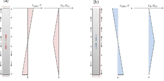
Assuming the simplified case of a homogenous, linear elastic, unrestrained pile, it is expected to expand during heating and contract during cooling causing additional axial tensile stress and changing the pile soil-interaction. The axial strain of an unconstrained pile (Eq. 1-17) depends only on the thermal expansion coefficient of each material and the temperature variation (Figure 1-5 (a)):
𝜺𝒐𝒃𝒔= 𝜺𝑭𝒓𝒆𝒆= 𝜶𝒄∆𝑻 Eq. 1-17
where 𝜀𝑜𝑏𝑠 is the observed (measured) axial strain, 𝜀𝐹𝑟𝑒𝑒 is the free axial strain of the pile
under thermal loading, αc is the coefficient of thermal expansion of concrete , ∆𝑻 is the
temperature change.
The stresses in the pile should always remain under the allowable limit. An extreme case for the evaluation of the additional stress that may develop in an energy pile consists in considering a fully restrained pile (Figure 1-5 (b), Eq. 1-18):
where σT is the additional thermal stress due to thermal loading for a fully constrained
pile, εb is the blocked axial strain and E is Young modulus.
In reality the boundary conditions may be somewhere in between fully restrained and unrestrained thus the axial strain due to thermal loading does not occur under free expansion conditions and thermally induced stresses arise along the foundation. This translates into the fact that although free expansion condition represents an upper limit for the magnitude of the pile deformation, the observed deformation may be significantly smaller and the remaining blocked deformation converts into thermal axial stress (Eq. 1-19).
Figure 1-5 Thermal response of a free and a completely restrained pile: (a) heating, free pile, (b) heating, restrained pile (after Bourne-Webb et al. 2013).
Figure 1-6 Effect of soil restraint on the response of energy piles during thermal loading: (a) heating, (b) cooling (after Bourne-Webb et al. 2013).
To illustrate this, the response to heating and cooling of a floating pile without mechanical loading is considered (Figure 1-6). As the soil strength and stiffness increase the restraint mobilised at the pile-soil interface increases. During heating, expansive strains at the mid –length of the pile will be more restrained than towards its extremities resulting in the development of compressive axial stress (Figure 1-6 (a)). Soil restraint during cooling leads to suppressed contractive strain, and thus tensile load will develop as soil resistance increases (Figure 1-6 (a), Eq. 1-19).
𝜺𝑭𝒓𝒆𝒆= 𝜺𝒐𝒃𝒔+ 𝜺𝒃 Eq. 1-19
where 𝜀𝐹𝑟𝑒𝑒 is the free axial strain of an energy pile, 𝜀𝑜𝑏𝑠 is the observed (measured) axial
strain of the pile under thermal loading and 𝜀𝑏 is the blocked axial strain (due to
restraints) of the pile under thermal loading.
1.4 Design and execution of energy piles
1.4.1 Short pile foundations overview
Foundations provide support for structures, transferring their load to layers of soil or rock that have sufficient bearing capacity and suitable settlement characteristics. There are a very wide range of foundation types available, suitable for different applications, depending on considerations, such as the supported load, ground conditions, cost, proximity to other structures etc. Very broadly foundations can be set in two categories: shallow and deep foundations respectively. Shallow foundations are commonly used when the structure loads are relatively low compared to the soil’s bearing capacity. Deep foundations on the other hand are used when the soil surface’s bearing capacity is insufficient to support the loads transferred by the superstructure and thus they are transferred to deeper layers with better mechanical properties.
Pile foundations are a type of deep foundations, formed by long slender columnar elements typically made from steel or reinforced concrete, or sometimes timber, having the distinct property of its depth being at least three times larger than its breath
(Atkinson, 2007). This type of deep foundations are principally used to transfer the loads from superstructures, through weak, compressible strata or water onto stronger, more compact, less compressible and stiffer soil or rock at depth, increasing the effective size of a foundation and resisting horizontal loads.
Piles may be classified by their basic design function as end-bearing, friction or a combination. End-bearing piles ( Figure 1-7 a) develop most of their capacity at the toe of the pile, bearing on a hard layer. The pile transmits load direct to firm strata, and also
receives lateral restraint from subsoil. Friction (or floating, Figure 1-7 b) piles develop most of the pile-bearing capacity by shear stresses along the sides of the pile, and are suitable where harder layers are too deep. The pile transmits the load to surrounding soil by friction between the surface of the pile and soil , which in effect lowers the bulb of pressure. Many piles exhibit though a combination of the two load transfer mechanisms ( Figure 1-7 c).
By their method of construction piles may be divided into displacement (driven) or replacement (bored) piles. Driven piles are normally made from pre-cast concrete which is then hammered into the ground once on site. Bored piles are cast in situ; the soil is bored out of the ground and then the concrete is poured into the hole. Alternatively, boring of the soil and pouring of the concrete can take place simultaneously, in which case the piles are called continuous fight auger piles (O’Sullivan, 2010).
Figure 1-7 Types of piles based on the method of load transfer: (a) end-bearing pile, (b) friction (floating) pile and (c) bearing-cum-friction pile.
The choice of pile used depends on the location and type of structure, the ground conditions, durability of the materials in the environment and cost. Most piles use some end bearing and some friction, in order to resist the action of loads. Driven piles are useful in offshore applications, are stable in soft squeezing soils, and can densify loose soil. However, bored piles are more popular in urban areas as there is minimal vibration, they can be used where headroom is limited, there is no risk of heave, and it is easy to vary their length (O’Sullivan, 2010).
Geothermal piles are a relatively new type of pile foundations combined with closed-loop ground source heat pump systems. Their purpose is to provide support to the building, as well as acting as a heat source and a heat sink. In effect, the thermal mass of the ground enables the building to store unwanted heat from cooling systems
1.4.2 Energy piles design
In recent years, design and execution recommendations have been proposed in some European countries (SIA 2005; GHSP 2012; CFMS-SYNTEC-SOFFONS-FNTP 2017) but an unified framework for the thermomechanical design of such foundations is still pending (Rotta Loria 2018). In any design scheme, though, two main issues need to be systematically considered: behaviour when in service and failure scenarios.
None of the existing standards and guidance documents offer any indication on how the thermal performance of an operating system should be measured and what failure criteria may be appropriate. In order to tackle this problem, Bourne-Webb et al. ( 2016) suggest a number of parameters to be accounted for in such a performance evaluation, listed in Table 1-2.
Regardless of the heat exchanger role of energy piles, their primary function remains to safely transfer loads without unacceptable movement or damage to the superstructure or neighbouring structures. In other words, the geotechnical energy pile design should follow the same reasoning as a classical pile design (i.e. SLS and ULS conditions) while incorporating an additional type of load, namely the thermal loading.
Energy delivered
An EGS scheme will be designed to deliver a certain proportion of the overlying buildings heating and cooling requirements and if this is not achieved then it may be considered to have failed. The
consequences of failure will be greatest when no backup system is available. A suggested recommended approach would be to consider a 10% margin between required and expected energy supply as a starting value and then to revise it on a project-by-project basis depending on the specific
conditions that occur.
Efficiency of system
The seasonal performance factor (SPF) gives the measured efficiency of an installed heat pump system. It is the ratio of the heat delivered for space heating and hot water and the electricity used to
run the system. Under the EU Renewable Energy Sources Directive [122], heat pumps are considered renewable if their SPF is greater than 2.5. This could also be a convenient measure of
acceptable serviceability performance of EGS.
System temperatures
More work is required to establish guidance on operational temperature limits for EGS. Current practice tends to recommend that the lower limit on the heat transfer fluid temperature in BHE & EGS should be kept above freezing with a 2 °C margin of error [117,118,123]. This is to ensure the ground does not freeze. It has been shown both theoretically and in practice, that for large diameter piles, temperatures lower than 0 °C can be sustained within the heat transfer fluid for short periods and have no detrimental effects on the ground [71,124]. Similar conclusions were reached by [6] but do
not seem to have been acted upon in general practice. Due to the impact of high temperatures on pump efficiency and thus SPF, the circulating fluid is usually kept below 40 °C, although values as
high as 60 °C are used [117].
Environmental
The development of SGE and EGS systems in the future will increasingly need to consider interactions with adjacent systems and/or the potential for heat to propagate outside site boundaries and thus, compromise future developments. Currently, there is no guidance or regulation relating to
this issue.
1.4.2.1 Classical pile design
Foundation design consists of selecting and proportioning foundations in such a way that limit states (Ultimate Limit State (ULS), Serviceability Limit State (SLS)) are prevented. The design must satisfy the requirements of the building code being in effect, specifically the Eurocode 7 and its National Annexes in European Union countries. EN 1997-1 states that the design of piles shall be based on one of the following approaches:
The results of static load tests, which have been demonstrated, by means of calculations or otherwise, to be consistent with other relevant experience
Empirical or analytical calculation methods whose validity has been demonstrated by static load tests in comparable situations
The results of dynamic load tests whose validity has been demonstrated by static load tests in comparable situations
The observed performance of a comparable pile foundation, provided that this approach is supported by the results of site investigation and ground testing The pile foundations need to be guaranteed with respect to:
ULS for a single pile and for the foundation as a whole, which means that an adequate safty margin against both structura and geotechnical failure must be ensured;
SLS which means that the absolute differential foundation settlement under working conditions must be within acceptable limits so that the comfort of the building is preserved.
The equilibrium equation to be satisfied in the ultimate limit state design of axially loaded piles in compression is presented in Eq. 1-20:
𝑭𝒄;𝒅≤ 𝑹𝒄;𝒅 Eq. 1-20
where 𝑭𝒄;𝒅 is the design axial compression load and 𝑹𝒄;𝒅 is the pile compressive design
resistance.
The design axial compressive load 𝑭𝒄;𝒅 is obtained by multiplying the
representative permanent and variable loads, 𝑮 and 𝑸 by their corresponding safety factors 𝜸𝑮 and 𝜸𝑸, as in Eq. 1-21:
𝑭𝒄;𝒅= 𝜸𝒇𝑭𝒓𝒆𝒑= 𝜸𝑮𝑮𝒓𝒆𝒑+ 𝜸𝑸𝑸𝒓𝒆𝒑 Eq. 1-21
The two sets of recommended partial factors on actions and the effects of actions provided in Annex A of EN 1997-1, reproduced in Table 1-3.
Action Symbole A1 Ensemble A2
Permanent Unfavorable Favorable 𝛾𝐺 1.35 1.0 1.0 1.0
Variable Unfavorable Favorable 𝛾𝑄 1.5 0 1.3 0
Table 1-3 Recommended safety factors on actions (EN 1997-1)
𝑭𝒓𝒆𝒑= 𝝍𝑭𝒌 Eq. 1-22
where 𝑭𝒓𝒆𝒑 is the relevant representative value of the action,𝑭𝒌 is the characteristic value
of the action, 𝜸𝒇 is the partial factor for the action which takes account of the possibility
of unfavourable deviations of the action values from the representative value and 𝝍 is equal to 1.00 or 𝝍𝟎 the factor for combination value of a variable action or𝝍𝟏 the factor
for frequent value of a variable action or 𝝍𝟐 the factor for quasi-permanent value of a
variable action.
For a specific load case the design values of the effects of actions (𝑬𝒅) can be
expressed in general terms as in Eq. 1-23:
𝑬𝒅= 𝜸𝑺𝒅𝑬{𝜸𝒇,𝒊𝑭𝒓𝒆𝒑,𝒊; 𝒂𝒅} Eq. 1-23
where 𝜸𝑺𝒅is a partial factor considering uncertainties in modelling the effect of actions
and in some cases, modelling the actions, 𝐚𝐝is the design value of the geometrical data.
Combination Permanent actions 𝑮𝒅 Prestress Variable actions 𝑸𝒅
Unfavourable Favourable Leading Others
Characteristic 𝐺𝑘,𝑗,𝑠𝑢𝑝 𝐺𝑘,𝑗,𝑖𝑛𝑓 𝑃 𝑄𝑘,1 Ψ0,𝑖𝑄𝑘,𝑖
Frequent 𝐺𝑘,𝑗,𝑠𝑢𝑝 𝐺𝑘,𝑗,𝑖𝑛𝑓 𝑃 Ψ1,1𝑄𝑘,1 Ψ2,𝑖𝑄𝑘,𝑖
Quasi-permanent 𝐺𝑘,𝑗,𝑠𝑢𝑝 𝐺𝑘,𝑗,𝑖𝑛𝑓 𝑃 Ψ2,1𝑄𝑘,1 Ψ2,𝑖𝑄𝑘,𝑖
Table 1-4 Recommended safety factors on actions (EN 1997-1).
The design axial compressive load shall be determined for all the following design situations:
Persistent design situations, which refer to the conditions of normal use
Transient design situations, which refer to temporary conditions applicable to the structure
Accidental design situations which refer to the exceptional conditions applicable to the structure or to its exposure
Seismic design situations, which refer to conditions applicable to the structure when subjected to seismic events.
The pile characteristic compressive resistance 𝑹𝒄;𝒌 may be determined according
to the Eurocode 7 either directly from static load tests, by calculation from profiles of ground test results or by calculation from ground parameters.
The design compressive resistance of a pile 𝑹𝒄;𝒅 may be obtained either by treating
the pile resistance as a total resistance (Eq. 1-24) or by separating it into base and shaft resistance (Eq. 1-25).
𝑹𝒄;𝒅= 𝑹𝒄;𝒌/𝜸𝒕 Eq. 1-24
𝑹𝒄;𝒅= 𝑹𝒃;𝒌/𝜸𝒃+ 𝑹𝒔;𝒌/𝜸𝒔 Eq. 1-25
For the serviceability limit state, the foundation displacements shall be assessed and checked against the rudiments given. This involves absolute settlements, tilt movements, and differential displacements.
There exist four approaches which can be adopted to predict the displacement of a single pile (Di Donna 2014):
Load settlement curves determined through in-situ load tests at the reak scale
Finite element analysis
Load transfer curves method
Analytical approximated solutions
Action 𝚿𝟎 𝚿𝟏 𝚿𝟐
Imposed loads in buildings, category (EN 1991-1-1): Category A: domestic, residential areas
Category B: office areas Category C: congregation areas
Category D: shopping areas Category E: storage areas Category F: traffic areas (vehicle weight ≤30kN) Category G: traffic area (30kN< vehicle weight≤160kN)
Category H: roofs 0.7 0.7 0.7 0.7 1.0 0.7 0.7 0.0 0.5 0.5 0.7 0.7 0.9 0.7 0.5 0.0 0.3 0.3 0.6 0.6 0.8 0.6 0.3 0.0 Snow loads on buildings (EN 1991-1-4)*
Finland, Iceland, Norway, Sweden
Remainder of CEN Member States, for sites located at altitude H>1000m a.s.l. Remainder of CEN Member States, for sites located at altitude H≤1000m a.s.l.
0.7 0.7 0.5 0.5 0.5 0.2 0.2 0.2 0.0
Wind loads on buildings (EN 1991-1-4) 0.6 0.2 0.0
Temperature (non-fire) in buildings (EN 1991-1-5) 0.6 0.5 0.0 NOTE:
The Ψ values may be set by the National Annex * For countries not mentioned above, see relevant local conditions
Table 1-5 Recommended safety factors on actions (EN 1997-1).
Resistance 𝜸𝑹 R1 Driven Piles R2 R3 R4 R1 R2 Bored piles R3 R4 R1 R2 CFA Piles R3 R4
Base 𝜸𝒃 1.0 1.1 1.0 1.3 1.25 1.1 1.0 1.6 1.1 1.1 1.0 1.45
Shaft 𝜸𝒔 1.0 1.1 1.0 1.3 1.0 1.1 1.0 1.3 1.0 1.1 1.0 1.3
Total 𝜸𝒕 1.0 1.1 1.0 1.3 1.15 1.1 1.0 1.5 1.1 1.1 1.0 1.4
Shaft in tension 𝜸𝒔𝒕 1.25 1.15 1.1 1.6 1.25 1.15 1.1 1.6 1.25 1.15 1.1 1.6
1.4.2.2 Energy pile design
Thermal loads due to the geothermal activation of a pile foundation can be considered variable static loads. The temperature change applied to energy piles can defined with reference to the temperature inputs involved in the building energy design, the associated thermal power for heating and cooling, the operation time and the thermal properties of the soil and of the ground. The resulting temperature changes are nominal values 𝜟𝑻𝒌 (Rotta Loria 2018). These values are likely between ±10°𝐶 (Vasilescu et al.
2019).
To appropriately consider the influence of thermal loads in the loads combinations, the factor for combination value of a variable action 𝝍𝟎, the factor for
frequent value of a variable action 𝝍𝟏 and the factor for quasi-permanent value of a variable action 𝝍𝟐 were chosen equal to 0.6, 0.5 and 0.2 respectively according to the
recommendations provided by CFMS-SYNTEC-SOFFONS-FNTP (2017).
Figure 1-8 The interactions between the geotechnical and thermal design processes (Bourne-Webb et al. 2016).
When considering the combinations of loads it should be accounted for the fact that for heating, it is not known a priori whether the involved effects make them the dominant load with respect to the other variable loads (Rotta Loria 2018). In consequence both cases when the thermal load is dominant and when one of the other variable loads is dominant should be considered
Any design also needs to consider the interactions between the geotechnical and thermal analysis as suggested by Bourne-Webb et al. (2016) and illustrated in Figure 1-8. In the simplest case, temperature limits are applied to both the geotechnical and
thermal design streams. However, these limits must first be agreed upon and may also require refinement during the design process.
1.4.2.3 Energy piles execution
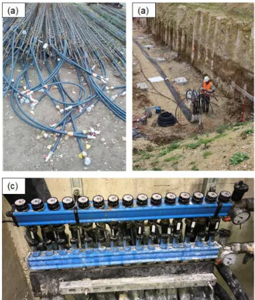
Structural piles are turned into heat exchangers by adding one or more loops of high-density polyethylene plastic pipes down their length. The geothermal loops are fixed on the reinforcement cages and then fitted with a locking valve and the manometer at the inlet and outlet ends. The pipes are filled with a fluid (gas or water) and pressurized for a first integrity test and to prevent collapse due to the fluid concrete. This pressure is ideally maintained during the entire construction period or at least during the concrete hardening.
Figure 1-9 Geothermal loops installation: (a) geothermal loops fixed on reinforcement cages, (b) Horizontal connections installation, (c) The manifold connecting all the geothermal loops to the
GSHP.
The loops are then lowered in the bored hole and concrete is poured using a tremie pipe for drilled piles or they are directly inserted in the fresh concrete in the case of CFA piles (Figure 1-9). Another integrity test is performed after concreting, after the installation of the horizontal connections to the heat pump and before starting the
2.
I
N SITU STUDY OF THERMOMECHANICAL
BEHAVIOUR OF ENERGY PILES
2.1 Introduction
The objective of this chapter is to identify and quantify the principal parameters involved in the design of energy pile foundations that are impacted by the changes in temperature associated with the geothermal activation of the foundation. For this purpose, the results from two full scale experimental campaigns are analysed hereafter. In the first case, an academic setup, with controlled loading conditions was studied. Two 12-m long concrete piles with a nominal diameter of 0.42 m were installed in a site including layers of clay and marl on the grounds of Ecole de Ponts Paris Tech, close to Paris. Several years after their installation, one of the two piles was first loaded to a pile head axial force of 600 kN, which corresponds to the assumed serviceability capacity. Afterward, while the pile head load was maintained constant, three thermal cycles were applied to the pile to simulate the seasonal thermal loading, using a refrigerated and heating circulator. The pile temperature, from its initial value (12.5 °C), varied between 4 °C and 25 °C.
Although the imposed temperature gradient for this test is similar to the annual heating/cooling average temperature variation observed in energy foundations of a typical building operation (McCartney and Murphy 2017), the functioning of a refrigerated and heating circulator is different from that of a heat pump commonly used in energy geostructures. Therefore, a second case study focusses on understanding the behaviour of energy piles in real exploitation conditions. Two energy piles and a conventional pile with the length of 9m and the diameter of 0.42m, were instrumented with vibrating wire sensors equipped with thermistors during the construction of the pre-treatment building of the Sept Sorts water treatment plant in Seine-et-Marne department, in France. Their behaviour under exploitation conditions was recorded for both conventional conditions and after the geothermal activation of the foundation.
2.2 Background
The knowledge on energy piles is progressively growing thanks to the increasing number of full-scale experiments (Laloui et al. 2003; Brandl 2006; Bourne-Webb et al. 2009; Martin et al. 2010; Singh et al. 2011; McCartney and Murphy 2012a; Akrouch et al. 2014; McCartney et al. 2015; Sutman et al. 2015; You et al. 2016; Sung et al. 2018). These studies point out the fact that using piles as heat exchangers induces additional deformations and stresses in the foundation, depending on the amplitude of the thermal load, the boundary conditions, and hydro-mechanical soil behaviour.
Figure 2-1 Pile head displacement due to imposed temperature changes during the construction of a four story building at the Swiss Federal Institute of Technology in Lausanne, Switzerland (Laloui et
al. 2003).
Based on experimental results Amatya et al. (2012) proposed a descriptive framework for explaining the response of thermomechanically loaded piles. When a pile is heated, it expands, but it is not able to expand freely due to the mobilization of side restraint at pile-soil interface and any end restraints either at the pile head or toe (Figure 2-1). As shown by the evolution of the strain profiles during heating and cooling tests performed at Lambeth College (Bourne-Webb et al. 2009) a floating pile exhibits no axial stress at the pile toe (Figure 2-2). On the other hand all the instrumented energy piles fixed in a stiff soil layer (Laloui et al. 2003; McCartney and Murphy 2012a; McCartney et al. 2015; Sutman et al. 2015; You et al. 2016) indicate an increase in the pile axial stress depending on the amplitude of the temperature change and the degree of ground resistance. Additionally, monitoring results reveal that additional pile head
displacement varies with the thermal loading (Laloui et al. 2003; Bourne-Webb et al. 2009; Akrouch et al. 2014) and a special attention should be paid during the design phase in order to avoid any impact on the structural integrity of the building.
Figure 2-2 Example of the effect of less stiffer pile toe and pile head boundary conditions: Clapham Centre of Lambeth College in London, England (Bourne-Webb et al. 2009) (a) The soil profile and the instrumentation of the tested pile, (b) The loads in the pile due to the mechanical loading, (c)
The loads in the pile due to the thermal loading.
Although no examples of foundation failure due to these temperature changes have been identified in the literature, the additional temperature-induced axial stress in the pile may be important, especially at the pile toe where the thermal effects may produce much larger axial stress (Figure 2-2 b and c) than those produced by mechanical loading (Laloui et al. 2006; McCartney and Murphy 2012a; Sutman et al. 2015; You et al. 2016)
Several short (from 1 day to several weeks) cyclic thermo-mechanical tests (Laloui et al. 2003; Laloui et al. 2006; McCartney and Murphy 2012a; McCartney et al. 2015; Olgun and Bowers 2016) indicate that the thermal loads dissipate as the
temperatures recover and regain their initial value, but that over several heating-cooling cycles the pile head settlement increases slightly.
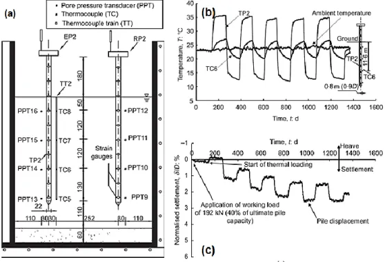
Less information is available in the literature concerning the effects of long-term operation of energy geostructures, namely the effect of long-term cyclic thermomechanical behaviour of energy piles (Brandl 2006; McCartney and Murphy 2012a; Murphy and McCartney 2015; McCartney and Murphy 2017). The long-term monitoring (5 years) of an 8 story building in Denver, Colorado (Figure 2-3 a, b, c) equipped with energy piles (Murphy and McCartney 2015), confirms the fact that, although daily temperature variations may be significant, the temperature profile evolution over the years follows a constant sinusoidal trend (Figure 2-3 b).
Figure 2-3 Long term therm-o mechanical behaviour of a energy pile under exploitation conditions (McCartney and Murphy 2017) (a) The soil profile and the instrumentation of the tested pile, (b)
The evolution of the temperature in the pile, (c) The evolution of deformations in the pile.
Physical models performed in small-scale energy pile showed irreversible settlement of the pile head when the number of thermal cycles increases (Figure 2-4 a, b, c, Ng et al. 2014; Yavari et al. 2014; Nguyen et al. 2017). Numerical studies investigating the thermo-mechanical behaviour of energy piles under several thermal cycles also confirmed the irreversible settlement related to thermal cycles (Laloui and Cekerevac 2008; Suryatriyastuti et al. 2012; Di Donna and Laloui 2015; Olgun et al.