UNIVERSITÉ DE MONTRÉAL
INTEGRATED COMMUNICATION AND RADAR SCHEME FOR FUTURE
INTELLIGENT TRANSPORTATION SYSTEMS
LIANG HAN
DÉPARTEMENT DE GÉNIE ÉLECTRIQUE ÉCOLE POLYTECHNIQUE DE MONTRÉAL
THÈSE PRÉSENTÉE EN VUE DE L‘OBTENTION DU DIPLÔME DE PHILOSOPHIAE DOCTOR (Ph.D.)
(GÉNIE ÉLECTRIQUE) Juin 2011
UNIVERSITÉ DE MONTRÉAL
ÉCOLE POLYTECHNIQUE DE MONTRÉAL
Cette thèse intitulée:
INTEGRATED COMMUNICATION AND RADAR SCHEME FOR FUTURE
INTELLIGENT TRANSPORTATION SYSTEMS
présentée par : HAN Liang
en vue de l‘obtention du diplôme de : Philosophiae Doctor a été dûment acceptée par le jury d‘examen constitué de : M. BOSISIO Renato, M.Sc.A., président
M. WU Ke, Ph.D., membre et directeur de recherche M. NERGUIZIAN Chahé, Ph.D., membre
DEDICATION
ACKNOWLEDGEMENT
First of all, I would like to express my sincere gratitude to my thesis supervisor, Dr. Ke Wu, who offered me an opportunity to pursue the PhD studies at the École Polytechnique de Montréal. This PhD project cannot be accomplished without his continuous support, his consistent encouragement, his inspiring guidance and his extraordinary foresight.
I am also very grateful to all the personnel at the Poly-Grames Research Center, especially all the technicians including Mr. Jules Gauthier, Mr. Traian Antonescu, Mr. Steve Dubé and Mr. Maxime Thibault. My gratitude extends to Mrs. Ginette Desparois for her assistance with all the administrative works and also to Mr. Jean-Sébastien Décarie for his technical support for solving all the IT problems.
My special thanks goes to the members of the examination jury for reading my thesis and providing their invaluable comments.
I would like to thank all the colleagues in the Poly-Grames Research Center, in particular Dr. Xiao-Ping Chen, Dr. Simone Winkler, Wen-Rui Li, Dr. Fanfan He, Dr. Lin Li and Dr. Ning Yang as well as all my friends in Canada and in China.
Last but not least, I would like to dedicate this thesis to my parents who gave me birth and brought me up. Additionally, I am very much indebted to my wife Mrs. Hongyan Zhou, who is always by my side.
RÉSUMÉ
Grâce à son impact social et économique, la journée mondiale de la santé 2004 a été dédiée à la sécurité routière. Le thème suivant : « La sécurité routière n‘est pas accidentelle» a été abordé. Suite à cette rencontre, une attention toute particulière a été donnée à la problématique des accidents de la route. Afin d‘augmenter la sécurité sur les routes et diminuer le nombre d‘accidents, des systèmes intelligents de transport (ITS) ont été proposés. Ces systèmes utilisent les technologies avancées de communication et de détection. La structure ITS associe les fonctionnalités des Radars et des communications sans fils, permettant de rendre les futurs véhicules intelligents autonomes et collaboratifs. Ces deux fonctions peuvent être réalisées en utilisant deux systèmes radiofréquences individuels et indépendants. Toutefois, une meilleure solution consiste à intégrer, dans un seul dispositif, le système de communication et le radar. Ceci permet d‘apporter de nombreux avantages comme par exemple la simplification et la miniaturisation du système, sa reconfigurabilité, l‘augmentation de son efficacité, et enfin cela permettrait de réduire fortement ses coûts de développement et de réalisation, élément clé pour réussir la commercialisation du véhicule intelligent.
Intrinsèquement, le fonctionnement des communications sans fils et des Radar ne sont pas compatibles. En effet, ils requièrent des techniques de conception et d‘implémentations différentes, ce qui les rend difficilement intégrables en un seul système. Afin de répondre aux grands défis technologiques présentés par cette intégration fonctionnelle, cette thèse de doctorat présente un développement compréhensif des systèmes intégrés de communication sans-fil et radar (iCars), placés dans un seul dispositif émetteur-récepteur et destinés aux futurs systèmes intelligents de transport.
Premièrement, après une recherche bibliographique approfondie, une nouvelle technique de modulation est proposée. Dans cette technique, les signaux radar et les signaux de communication sont arrangés en créneaux temporels séquentiels pendant un cycle d‘opération, minimisant ainsi leurs interférences mutuelles. Cette technique permet d‘obtenir une agilité temporelle et/ou une reconfigurabilité fonctionnelle, par l‘ajustement adaptatif ou cognitif de toutes les durées de modulation de la forme d‘onde, en accord avec les situations spécifiques de l‘utilisation. De plus, une fusion fonctionnelle de deux modes d‘opération devient possible en considérant les deux aspects suivants : le premier est que la portée et la vélocité obtenues en
mode radar peuvent être utilisées en mode communication afin de réduire la propagation par trajets multiples et afin de compenser l‘étalement Doppler causé par la mobilité des unités intégrées. Le deuxième aspect se présente dans l‘utilisation de la fonction de communication où différents émetteurs-récepteurs intégrés peuvent échanger des données pertinentes comme par exemple la distance et la vélocité d‘une cible. Ceci peut mener au développement des réseaux de radar avec une portée et une précision améliorées. Enfin, d‘un point de vue de réseautage, la modulation de la forme d‘onde proposée est avantageuse puisqu‘un créneau temporel spécifique peut alors être assigné à chaque unité dans la même cellule conformément à la méthode d‘accès multiple par répartition temporelle, tandis que différentes cellules peuvent utiliser différentes fréquences dans la transmission des données conformément à la méthode d‘accès multiple par répartition fréquentielle. Finalement, la technique de modulation proposée est avantageuse, d‘un point de vu interconnexion. En effet, un point temporel spécifique peut être assigné à chaque unité d‘une même cellule basé sur un multiplexage temporel (TDMA) tandis que différentes cellules peuvent utiliser différentes fréquences pour la transmission des données, cette fois-ci basé sur un multiplexage fréquentiel (FDMA).
Afin de confirmer le concept du système proposé, un prototype est réalisé fonctionnant à 5.9 GHz, Aux États-Unis, cette bande de fréquence a été allouée, par le FCC (Federal Communication Commission), aux applications de communications à courtes portées (DSRC). Conformément aux règlements de la FCC et à la demande des applications automobiles, les spécifications du système sont déterminées. Ensuite, une analyse du bilan de liaison est effectuée pour le mode radar et le mode communication. Cette analyse permet de mieux connaître les aspects théoriques de la fonctionnalité du système, et permet de déterminer les considérations spécifiques pour la conception. Un émetteur-récepteur hétérodyne conventionnel est modifié pour mettre en forme le type de modulation proposé. Ensuite, le système entier est modélisé puis analysé dans un environnement commercial de simulation afin d‘optimiser la performance du système. Suite à une analyse poussée du système et une simulation méticuleuse, un prototype est réalisé utilisant des composants commerciaux. Des expérimentations sont également entreprise afin d‘évaluer la performance du système en fonction des modes radar et de communication. Le taux d‘erreur (BER)mesuré est en très bonne accord avec les valeurs théoriques. Les distances et vélocités détectées présentent une très petite erreur comparativement aux valeurs prédéfinies dans l‘émulateur du canal.
Afin d‘améliorer le débit de transfert des données dans le mode de communication et la résolution de portée dans le mode radar, un deuxième prototype est réalisé fonctionnant dans la bande ISM, c'est-à-dire autour de 24 GHz. Ce système est conçu à l‘aide d‘une technologie de guides d‘onde intégrés sur substrat, qui présente plusieurs avantages comme par exemple son faible coût et sa compatibilité avec la technologie des circuits imprimés. Dans ce système, différents composants passifs issus de la technologie des guides d‘ondes intégrés sur substrat, tels que des coupleurs larges bandes, des déphaseurs larges bandes et des filtres à haute sélectivité sont proposés. Ces circuits sont réalisés à partir d‘une nouvelle méthode de conception utilisant des techniques de calibration numérique. En particulier, une méthode efficace et précise pour la synthèse des coupleurs interdigitaux (Lange) est proposée. En outre, une stratégie de modélisation est présentée pour la caractérisation et l‘extraction des modèles équivalents de circuit du couplage mutuel d‘ordre arbitraire. Cette technique est ensuite appliquée à la conception d‘une paire de réseaux micro-ruban 8x8 fonctionnant à 24 GHz. Finalement, en intégrant les composants passifs en technologie guide d‘onde intégrés sur substrat et les composants commerciaux, le système final fonctionnant à 24 GHz intégrant à la fois le système de communication haute vitesse et le système de détection de cibles haute précision, est réalisé.
Le système présenté dans cette thèse, intégrant des fonctionnabilités radar et de communication, a été démontré comme étant un système faible coût et apparait comme une solution avantageuse pour les fonctions requises des futures IVs. Ce produit peut aussi être très bénéfique pour l‘industrie automobile du fait de sa simplicité d‘architecture et de ses possibilités de reconfiguration.
ABSTRACT
Due to its growing social and economic impact, the world health day of 2004 was dedicated to road safety with its theme as ―Road safety is no accident‖. Thereafter, road traffic accidents have received unprecedented attention. In order to improve road safety, intelligent transportation systems (ITSs) have been proposed and deployed by making use of advanced information and communication technologies. Within the framework of ITSs, both wireless communication and radar sensing functions are indispensable for autonomous and cooperative operations of future intelligent vehicles (IVs). These two functions can definitely be achieved by using two individual and independent wireless systems. However, an attractive solution would be to integrate both communication and radar functions within a single transceiver platform, which could bring a lot of benefits such as system simplification and miniaturization, functional reconfiguration and fusion (mutual penetration and rapid processing/control of information), and especially efficiency enhancement and cost reduction that are the keys to the successful development and marketing of IVs.
Intrinsically, wireless communication and radar systems have incompatible operation principles, which require different design considerations and system implementations with respect to modulation techniques, required bandwidth, signal propagation and detection. To respond to these unprecedented design and technological challenges posed by the functional integration, this PhD thesis presents comprehensive study and development of integrated
communication and radar systems (iCars) based on a single transceiver platform for future ITSs.
Following a broad and in-depth literature review, first of all, a novel modulation scheme is proposed in this work, in which radar and communication signals are arranged in sequential time slots of one operation cycle and therefore, their interference is minimized. Also, time-agility or flexible functional reconfiguration can be easily achieved by adaptively or cognitively adjusting all software-programmable time durations in the modulation waveform according to usage situations. Moreover, functional fusion between two operation modes can be made possible from the following two aspects. One is that targets‘ ranges and velocities obtained through the radar mode can be used in the communication mode to mitigate multipath fading and compensate the Doppler spreading effect caused by the mobility of onboard units. The other is that by making use of the communication features, different onboard transceivers can exchange data such as
targets‘ range and velocities, which in fact forms a radar network with range increment and accuracy enhancement of target finding. Finally, the proposed modulation waveform is advantageous from a networking perspective since a specific time slot can be assigned to each unit in the same service cell on the basis of a time division multiple access (TDMA) while different service cells can use different frequencies for data transmission based on the frequency division multiple access (FDMA).
In order to prove our proposed system concept, a low-frequency system demonstrator has been built in the 5.9-GHz band assigned by the U.S. federal communications commission‘s (FCC‘s) for dedicated short range communication (DSRC) applications. Based on the FCC‘s rules and practical requirements of automotive applications, system specifications are defined and then link budget analysis is performed for both radar and communication modes in order to provide theoretical insight into system functionality and understand special design considerations. Conventional heterodyne transceiver architecture is modified to adapt our proposed modulation waveform. Subsequently, the entire system is modeled and analyzed in a commercial simulation package in order to find out achievable system performance as well as perform system optimization. On the basis of careful system analysis and simulation, the proposed low-frequency system prototype is built with commercial off-the-shelf components, and experiments are carried out to evaluate system performance for both radar and communication modes. Measured bit-error-rate (BER) in the communication mode agrees very well with theoretical values, and measured detection ranges and velocities in the radar mode exhibit very small error compared to the predefined values in the channel emulator.
For enhancing data rate in the communication mode and range resolution in the radar mode, another high-frequency system has been designed and prototyped in the 24-GHz industrial, scientific and medical (ISM)-band with the help of the emerging substrate integrated waveguide (SIW) technology, which has presented multiple advantages such as low cost, high quality-factor (high-Q) and versatile compatibility with standard printed circuit board (PCB) process. In this 24-GHz system, a number of innovative SIW passive components including wideband couplers, broadband phase shifters and highly-selective filters have been proposed together with novel design and synthesis method by virtue of numerical calibration techniques. In particular, an accurate and efficient method has been proposed to synthesize four-line interdigitated (Lange) coupler. Moreover, a fundamental modeling strategy has also been proposed to characterize and
establish equivalent circuit models of mutual coupling of any orders and this modeling technique is then applied in the design of a pair of 8×8 microstrip array at 24 GHz. Finally, by integrating our developed SIW passive components with commercial off-the-shelf active devices, the entire 24-GHz system is designed and prototyped onto a single substrate. Experimental results show very promising system performance for both high speed data communication and high accuracy target detection.
The integrated communication and radar scheme proposed in this thesis has been demonstrated as a cost-effective and advantageous solution for the functional requirements of future IVs. It will eventually benefit the automotive industry due to its low cost, simple system architecture, high efficiency and reconfigurable functionality.
TABLE OF CONTENTS
DEDICATION ... III ACKNOWLEDGEMENT ... IV RÉSUMÉ ... V ABSTRACT ... VIII TABLE OF CONTENTS ... XI LIST OF TABLES ... XVI LIST OF FIGURES ... XVIII LIST OF ACRONYMS AND ABBREVIATIONS ... XXVIIINTRODUCTION ... 1
CHAPTER 1 DESIGN CONSIDERATIONS AND SYSTEM CONCEPT ... 16
1.1 Basic digital bandpass modulations and quadrature demodulation for radio communications ... 16
1.1.1 Amplitude shift keying ... 17
1.1.2 Frequency shift keying ... 18
1.1.3 Phase shift keying ... 19
1.1.4 Quadrature amplitude modulation ... 20
1.1.5 Quadrature demodulation ... 21
1.2 Brief introduction to continuous wave radar ... 22
1.2.1 Doppler radar ... 23
1.2.2 Discrimination of the sign of the beat frequency ... 25
1.2.3 Frequency-modulated continuous wave radar ... 26
1.3 Design considerations ... 29
1.3.2 Modulation scheme and bandwidth requirements ... 31
1.3.3 Duplex mode ... 32
1.3.4 Digital signal processing ... 32
1.4 Proposed modulation scheme ... 32
1.4.1 Phase continuity condition ... 34
1.4.2 Operation of the radar mode ... 36
1.4.3 Operation of the radio mode ... 40
1.4.4 System synchronization ... 40
1.4.5 Summary ... 40
1.5 Conclusion ... 41
CHAPTER 2 A LOW-FREQUENCY SYSTEM DEMONSTRATOR: DESIGN, SIMULATION AND VALIDATION ... 42
2.1 System analysis ... 42
2.1.1 Brief review of the FCC‘s DSRC protocol ... 42
2.1.2 System specifications and link budget analysis ... 44
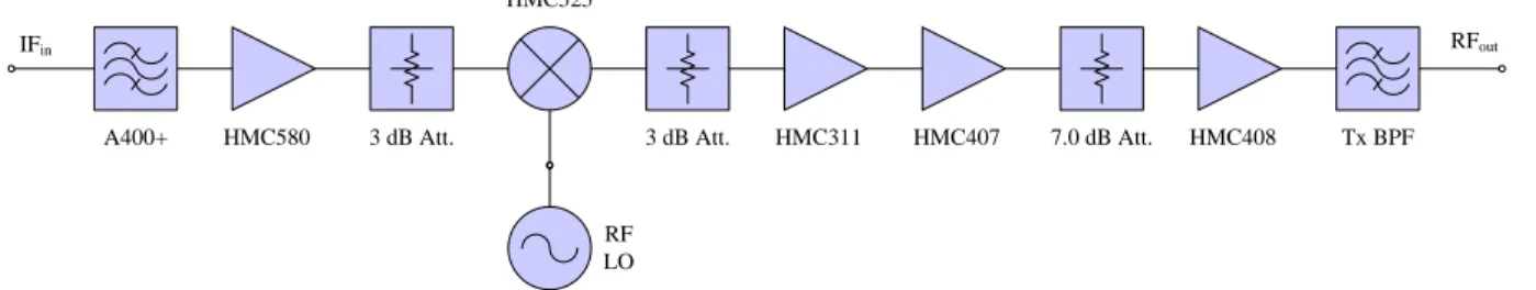
2.1.3 Transceiver architecture ... 47
2.2 System simulation ... 48
2.2.1 Simulation of the upconverter ... 48
2.2.2 Simulation of the downconverter ... 52
2.2.3 System-level simulation ... 54
2.3 Conclusion ... 59
CHAPTER 3 A LOW-FREQUENCY SYSTEM DEMONSTRATOR: PROTOTYPING AND EXPERIMENT ... 60
3.1 Circuits design and system prototyping ... 60
3.1.2 ALC and AGC circuits ... 61
3.1.3 SIW bandpass filters ... 61
3.1.4 Microstrip array antenna ... 68
3.1.5 System prototyping and housing ... 73
3.2 Measurement of circuit prototypes ... 75
3.2.1 Modulator ... 75
3.2.2 ALC circuit ... 76
3.2.3 Upconverter ... 77
3.2.4 Active power divider ... 81
3.2.5 Downconverter ... 83
3.2.6 AGC circuit ... 86
3.3 System measurement ... 87
3.3.1 Measurement of the receiver prototype ... 87
3.3.2 Laboratory experiment ... 91
3.3.3 Experiment on terrace ... 98
3.4 Conclusion ... 99
CHAPTER 4 A 24-GHZ SYSTEM PROTOTYPE: ANALYSIS AND SIMULATION ... 100
4.1 System analysis ... 100
4.1.1 System specifications and link budget analysis ... 100
4.1.2 Transceiver architecture ... 103
4.2 System simulation ... 103
4.2.1 Chain budget simulation of the upconverter ... 103
4.2.2 Chain budget simulation of the downconverter ... 105
4.3 Conclusion ... 108
CHAPTER 5 DESIGN OF PASSIVE COMPONENTS FOR 24-GHZ SYSTEM PROTOTPYE ... 109
5.1 Wideband 3-dB 90º SIW couplers ... 109
5.1.1 Operation principle of Riblet hybrid ... 110
5.1.2 Extraction of the propagation constants of even and odd modes ... 110
5.1.3 Model fitting ... 113
5.1.4 Parametric studies of the tapered coupling section ... 115
5.1.5 Equivalent circuit model of bifurcation effects ... 117
5.1.6 Design examples ... 119
5.2 Broadband SIW phase shifter ... 124
5.2.1 Theoretical analysis ... 124
5.2.2 Design examples ... 127
5.3 Wideband 3-dB 180º SIW couplers ... 131
5.4 Highly-selective SIW bandpass filters ... 135
5.4.1 SIW RF BPF ... 135
5.4.2 SIW Tx/Rx BPF ... 137
5.5 Four-line interdigitated coupler ... 139
5.5.1 Analysis of symmetrical four-line circuits ... 142
5.5.2 Synthesis of interdigitated couplers ... 148
5.5.3 Design examples ... 153
5.6 Conclusion ... 165
CHAPTER 6 MODELING OF MUTUAL COUPLING AND DESIGN OF 24-GHZ ARRAY ANTENNA ... 166
6.2 Description of coupling decomposition ... 169
6.3 Modeling of mutual coupling in one-dimensional structures ... 170
6.3.1 Design of a single radiating element ... 170
6.3.2 Modeling of first-order mutual coupling ... 171
6.3.3 Modeling of second-order mutual coupling ... 175
6.3.4 Modeling of higher-order mutual coupling ... 178
6.3.5 Application examples ... 179
6.4 Modeling of mutual coupling in two-dimensional structures ... 191
6.4.1 Modeling of first-order mutual coupling ... 191
6.4.2 Modeling of second-order mutual coupling ... 194
6.4.3 Application examples ... 197
6.5 Conclusion ... 209
CHAPTER 7 A 24 GHZ SYSTEM PROTOTYPE: INTEGRATION AND MEASUREMENT ... 210 7.1 System prototyping ... 210 7.2 Experimental results ... 211 7.2.1 Radio mode ... 211 7.2.2 Radar mode ... 216 7.3 Conclusion ... 222
CONCLUSION AND FUTURE WORK ... 223
BIBLIOGRAPHIE ... 227
LIST OF TABLES
Table 1 Performance comparisons of available sensing technologies. ... 2
Table 2.1 Channel allocation for DSRC. ... 42
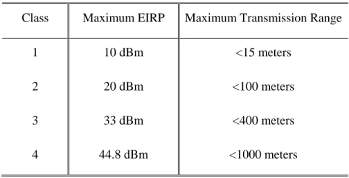
Table 2.2 Four classes of DSRC devices. ... 43
Table 2.3 Four installation classes. ... 44
Table 2.4 Specifications of 5.9-GHz system demonstrator. ... 45
Table 2.5 Link budget analysis for 5.9-GHz system demonstrator. ... 46
Table 2.6 Simulation results of the radar mode. ... 57
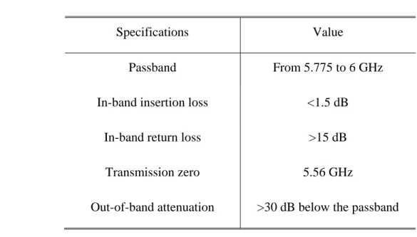
Table 3.1 Specifications of the Tx BPF. ... 62
Table 3.2 Specifications of the Rx BPF. ... 65
Table 3.3 Comparison between predefined values and measurement results. ... 94
Table 3.4 Mean and standard deviation of delay measurement. ... 95
Table 3.5 Mean and standard deviation of velocity measurement. ... 96
Table 4.1 System specifications of 24-GHz system prototype. ... 101
Table 4.2 Link budget analysis for 24-GHz system prototype. ... 102
Table 4.3 Simulation results of the radar mode. ... 106
Table 5.1 Dimensions of the prototyped 3-dB 90º SIW coupler. ... 120
Table 5.2 Two solutions of synthesized phase shifter. ... 128
Table 5.3 Dimensions of the proposed 3-dB 180º SIW coupler. ... 131
Table 5.4 Performance comparison between this work and a reference work. ... 133
Table 5.5 Specifications of the RF BPF. ... 135
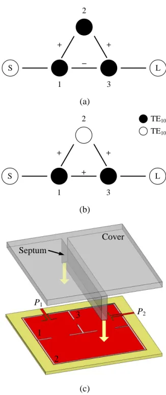
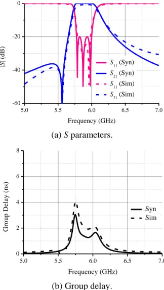
Table 5.6 Specifications of the Tx/Rx BPF. ... 137
Table 5.7 Extracted parametric values of equivalent circuit model in 1025HFigure 5.32. ... 157
Table 6.2 Comparison of array gains calculated by three different methods. ... 183 Table 6.3 Optimum physical dimensions of the 24-GHz patch. ... 204
LIST OF FIGURES
Figure 1 Application scenarios of iCars. ... 4
Figure 2 Benefits of functional integration. ... 4
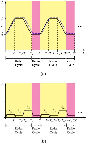
Figure 3 (a) Proposed time-agile modulation waveform and (b) beat frequencies at the output of the receiving front-end. ... 8
Figure 4 Three typical family members of SICs. ... 12
Figure 1.1 A digital bandpass modulator. ... 17
Figure 1.2 (a) Waveform and (b) constellation diagram of OOK signal. ... 18
Figure 1.3 (a) Waveform and (b) constellation diagram of BFSK signal. ... 19
Figure 1.4 (a) Waveform and (b) constellation diagram of BPSK signal. ... 19
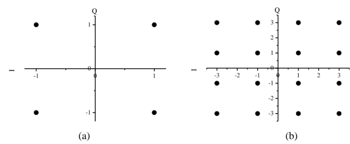
Figure 1.5 Constellation diagram of (a) 4QAM (QPSK) signal and (b) 16QAM signal. ... 20
Figure 1.6 Block diagram of an ideal quadrature demodulator. ... 21
Figure 1.7 Operation principle of the Doppler radar. ... 23
Figure 1.8 Transmitted and received waveforms of a Doppler radar. ... 23
Figure 1.9 Transmitted and received waveforms of triangular FMCW signal. ... 27
Figure 1.10 (a) Triangular FMCW signal and (b) the beat frequency. ... 27
Figure 1.11 Wave propagation for radio communications. ... 29
Figure 1.12 Wave propagation for radar sensing. ... 30
Figure 1.13 Time-agile modulation waveform. ... 33
Figure 1.14 Spectrum of modulated waveform for different conditions of phase continuity. .. 36
Figure 2.1 Transceiver architecture of 5.9-GHz system demonstrator. ... 47
Figure 2.2 Block diagram of the transmitter. ... 49
Figure 2.3 Simulation diagram of the upconverter. ... 49
Figure 2.5 Simulated gain compression characteristics of the upconverter. ... 50
Figure 2.6 Simulated chain budget of the upconverter. ... 51
Figure 2.7 Block diagram of the receiver. ... 52
Figure 2.8 Simulation diagram of the downconverter. ... 52
Figure 2.9 Simulated output gain of the downconverter. ... 53
Figure 2.10 Simulated gain compression characteristics of the downconverter. ... 53
Figure 2.11 Simulated chain budget of the downconverter. ... 54
Figure 2.12 System simulation diagram. ... 55
Figure 2.13 Simulated modulated waveforms. ... 56
Figure 2.14 Comparison between transmitted and received radio baseband signals. ... 58
Figure 2.15 Simulated BER of the radio mode. ... 59
Figure 3.1 Photo of the DDS evaluation board. ... 60
Figure 3.2 Block diagram of the ALC/AGC circuit. ... 61
Figure 3.3 Sketch of the Tx BPF and its equivalent circuit topology. ... 63
Figure 3.4 Comparison between synthesized and simulated results of the Tx BPF. ... 64
Figure 3.5 Sketch of the Rx BPF and its equivalent circuit topology. ... 66
Figure 3.6 Comparison between synthesized and simulated results of the Rx BPF. ... 67
Figure 3.7 Sketch of an element in the array. ... 68
Figure 3.8 Comparison between simulated and measured return losses of the element. ... 69
Figure 3.9 Comparison between simulated and measured gains of the element. ... 69
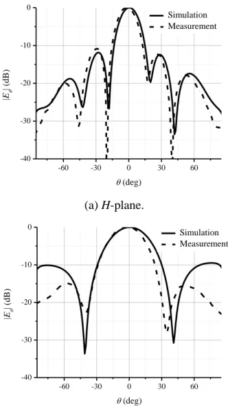
Figure 3.10 Comparison between simulated and measured radiation patterns of the element. . 70
Figure 3.11 Sketch of the planar array. ... 71
Figure 3.12 Comparison between simulated and measured return losses of the array. ... 71
Figure 3.14 Comparison between simulated and measured gains of the array. ... 73
Figure 3.15 Illustration of Tx and Rx housings. ... 74
Figure 3.16 Photos of Tx and Rx prototypes. ... 75
Figure 3.17 Measured sideband suppression of the modulator. ... 76
Figure 3.18 Measured ALC performance. ... 77
Figure 3.19 Measured intermodulation performance of the upconverter. ... 78
Figure 3.20 Measured sideband suppression performance of the upconverter. ... 79
Figure 3.21 Measured EVM of BPSK signals. ... 80
Figure 3.22 Measured EVM of QPSK signals. ... 80
Figure 3.23 Measured EVM of 16QAM signals. ... 81
Figure 3.24 Measured performances of the active power divider. ... 82
Figure 3.25 Measured gain and noise figure of the downconverter. ... 83
Figure 3.26 Measured intermodulation performance of the downconverter. ... 84
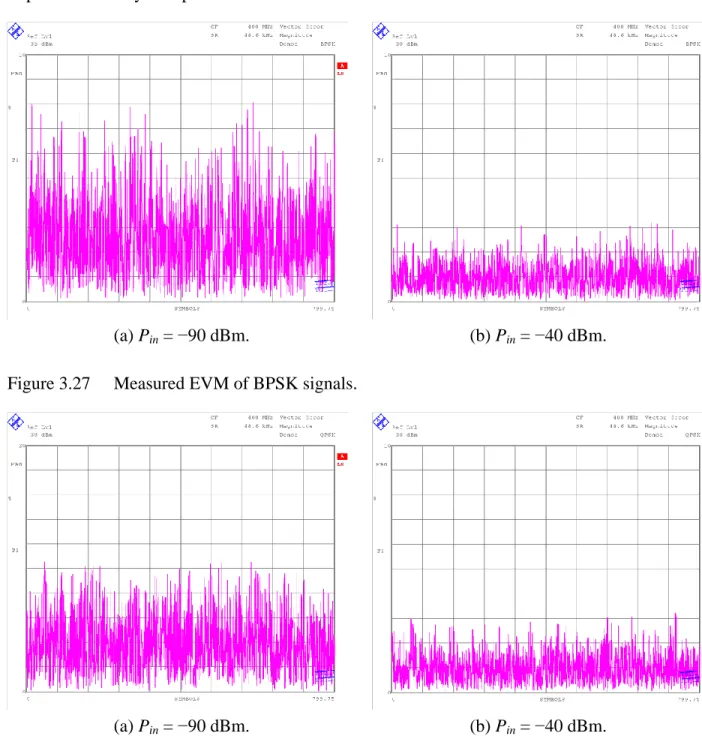
Figure 3.27 Measured EVM of BPSK signals. ... 85
Figure 3.28 Measured EVM of QPSK signals. ... 85
Figure 3.29 Measured EVM of 16QAM signals. ... 86
Figure 3.30 Measured AGC performance. ... 86
Figure 3.31 Experiment setup for measuring the constellation of demodulated signal. ... 87
Figure 3.32 Measured constellation of BPSK signals. ... 88
Figure 3.33 Measured constellation of 8PSK signals. ... 88
Figure 3.34 Measured constellation of 16QAM signals. ... 89
Figure 3.35 Measured results of BPSK signals for a data rate of 24.3 kbps. ... 90
Figure 3.36 Measured results of BPSK signals for a data rate of 48.6 kbps. ... 90
Figure 3.38 BER measurement setup. ... 92
Figure 3.39 BER measurement results. ... 92
Figure 3.40 Measurement setup of the radar mode. ... 93
Figure 3.41 Measured results of the radar mode. ... 95
Figure 3.42 A typical waveform of the received signal for a static object. ... 97
Figure 3.43 Comparison between transmitted data, received data and recovered data. ... 97
Figure 3.44 Experiment setup for measuring the distance of a baluster. ... 98
Figure 3.45 Measured results of the baluster. ... 98
Figure 4.1 Transceiver architecture of 24-GHz system prototype. ... 103
Figure 4.2 Simulation diagram of the upconverter. ... 104
Figure 4.3 Simulated chain budget of the upconverter. ... 104
Figure 4.4 Simulation diagram of the downconverter. ... 105
Figure 4.5 Simulated chain budget of the downconverter. ... 105
Figure 4.6 Comparison between transmitted and received radio baseband signals. ... 107
Figure 5.1 Simplified sketch of circularly-tapered SIW directional coupler. ... 110
Figure 5.2 Full-wave model of an arbitrary SIW discontinuity (a) and its equivalent circuit topology (b) as well as the numerical TRL calibration kits (c)-(e). ... 111
Figure 5.3 Extracted frequency-dependent results versus cell number. ... 113
Figure 5.4 Fitting the tapered coupling section (a) to the model of a uniform rectangular waveguide (b). ... 114
Figure 5.5 Results of model fitting and relative error representations. ... 114
Figure 5.6 Extracted frequency-dependent results versus different cell number. ... 116
Figure 5.7 (a) Simplified model of bifurcation and (b) its equivalent circuit model. ... 117
Figure 5.9 Comparison between simulated and measured results of the proposed 3-dB 90º SIW coupler. ... 121 Figure 5.10 Comparison between simulated and measured results of an SIW crossover. ... 122 Figure 5.11 Simulated results of 24-GHz 3-dB 90º SIW coupler. ... 123 Figure 5.12 Illustration of dielectric-filled rectangular waveguide models. ... 124 Figure 5.13 Design flow chart of the proposed phase shifter. ... 127 Figure 5.14 Comparison between synthesized and full-wave simulation results. ... 128 Figure 5.15 Extracted equivalent permittivity of three commonly-used substrates for the SIW
technology. ... 129 Figure 5.16 Photo of the fabricated samples of SIW phase shifters. ... 129 Figure 5.17 Comparison between simulated and measured S parameters of the fabricated
prototype. ... 130 Figure 5.18 Comparison of phase shift and amplitude imbalance. ... 130 Figure 5.19 Simplified sketch of 3-dB 180º SIW directional coupler. ... 131 Figure 5.20 Photo of the prototype of the 3-dB 180º SIW coupler. ... 132 Figure 5.21 Performance comparison of the 3-dB 180º SIW coupler. ... 134 Figure 5.22 Sketch of the 24-GHz RF BPF. ... 136 Figure 5.23 Comparison between simulated and measured results of the RF BPF. ... 137 Figure 5.24 (a) Sketch of the 24-GHz Tx/Rx BPF and (b) its equivalent filter topology. ... 138 Figure 5.25 Comparison between simulated and measured results of the Tx/Rx BPF. ... 139 Figure 5.26 Symmetrical four coupled-lines. ... 141 Figure 5.27 Voltage distributions for four normal modes. ... 144 Figure 5.28 Schematic description of a four-line interdigitated coupler. ... 148 Figure 5.29 Simplified solution of the original four-line structure. ... 151
Figure 5.30 Reference chart for the four-line interdigitated coupler on the specified substrate. ... ... 153 Figure 5.31 Sketch of an unfolded four-line Lange coupler. ... 154 Figure 5.32 Equivalent circuit model of the Lange coupler in 1018HFigure 5.31. ... 155 Figure 5.33 Extracted inductances of bonding wires with different heights. ... 155 Figure 5.34 Comparison among circuit simulation and full-wave simulation results as well as
synthesized results. ... 156 Figure 5.35 Comparison between simulated and measured performance. ... 159 Figure 5.36 An SEM photo of the fabricated Lange coupler before bonding wires assembly. ...
... 160 Figure 5.37 Test fixture with Lange coupler mounted. ... 160 Figure 5.38 Sketch of a composite microstrip-CPW coupler. ... 162 Figure 5.39 Reference chart for designing the composite microstrip-CPW coupler. ... 163 Figure 5.40 Comparison between simulation and measurement. ... 164 Figure 5.41 Measurement setup using a four-port VNA. ... 165 Figure 6.1 Mutually coupled elements numerated from 1 to N. ... 169 Figure 6.2 Return loss of a single microstrip inset-fed patch antenna. ... 171 Figure 6.3 Two adjacent coupled circuit elements. ... 172 Figure 6.4 Modeling of first-order mutual coupling. ... 173 Figure 6.5 Extracted results of first-order mutual coupling. ... 174 Figure 6.6 Three coupled elements. ... 175 Figure 6.7 Modeling of second-order mutual coupling. ... 176 Figure 6.8 Extracted results of second-order mutual coupling. ... 177 Figure 6.9 Comparison of extracted first-order and second-order mutual admittances. ... 178 Figure 6.10 Comparison of mutual coupling of different orders. ... 179
Figure 6.11 Flowchart of successive modeling of arbitrary-order mutual coupling. ... 179 Figure 6.12 A linear phased array antenna composed of 19 half-wavelength-spaced elements. ..
... 180 Figure 6.13 Influences of neighbouring elements on the host element. ... 181 Figure 6.14 Array patterns comparison. ... 182 Figure 6.15 A periodic structure of finite size consisting of N microstrip stubs. ... 184 Figure 6.16 (a) A microstrip stub and (b) its equivalent circuit model. ... 184 Figure 6.17 Extracted parameters of the equivalent circuit model shown in 1119HFigure 6.16(b). . 185 Figure 6.18 (a) Two mutually coupled microstrip stubs and (b) its equivalent circuit topology. ..
... 185 Figure 6.19 Scattering coefficients S11 (solid line) and S12 (dash dot line) of the mutual
coupling network versus the physical dimension. ... 186 Figure 6.20 Simulated and measured return losses of two microstrip periodic structures with
different spacing D between the stubs when the stub width W is fixed at 0.5 mm. ... ... 188 Figure 6.21 Ideal S-parameters response and equivalent circuit network modeling results
excluding mutual coupling (MC denotes mutual coupling). ... 189 Figure 6.22 Ideal response, full-wave simulation, and equivalent circuit network modeling
results including mutual coupling effect. ... 190 Figure 6.23 Comparison between the ideal, the optimized, and the measured responses. (The
unit of all physical dimensions is mm.) ... 190 Figure 6.24 Two coupled microstrip patch antennas. ... 191 Figure 6.25 Equivalent circuit topology of two adjacent coupled elements. ... 191 Figure 6.26 Extracted Yd. ... 192
Figure 6.27 Extracted Y(1) 12. ... 193 Figure 6.28 Three coupled elements in a planar configuration. ... 194
Figure 6.29 Equivalent network topology for extracting second-order mutual coupling. ... 195 Figure 6.30 Extracted equivalent circuit parameters of second-order mutual coupling in an
echelon configuration. ... 195 Figure 6.31 Extracted equivalent circuit parameters of second-order mutual coupling in a
collinear configuration. ... 196 Figure 6.32 Extracted equivalent circuit parameters of second-order mutual coupling in a
broadside configuration. ... 196 Figure 6.33 Illustration of a 3×3 microstrip phased array antenna. ... 197 Figure 6.34 Calculated active element patterns of different elements at (a) xoz-plane and (b)
yoz-plane. ... 199
Figure 6.35 Calculated array pattern. ... 200 Figure 6.36 Inset-fed microstrip rectangular patch loaded with two straight slots. ... 201 Figure 6.37 Current distributions of the fundamental mode for (a) slotted patch and (b)
conventional patch. ... 202 Figure 6.38 Results of parametric study. ... 203 Figure 6.39 Comparison of return losses of a slotted patch and a conventional patch. ... 204 Figure 6.40 Sketch of an 8×8 corporate-fed planar array. ... 205 Figure 6.41 Synthesized results. ... 206 Figure 6.42 Photo of the fabricated prototype of the 24-GHz planar array. ... 207 Figure 6.43 Comparison between simulated and measured return loss of the planar array. ... 208 Figure 6.44 Measured gain of the 24-GHz planar array over frequencies. ... 208 Figure 6.45 Measured radiation pattern of the array. ... 209 Figure 7.1 3D sketch of the housings for 24-GHz system prototype. ... 210 Figure 7.2 Photos of the fabricated transmitter and receiver prototype. ... 211 Figure 7.3 Measurement setup for evaluating system performance of the radio mode. ... 212
Figure 7.4 Measured results for BPSK signals with an input power of −60 dBm. ... 212 Figure 7.5 Measured results for QPSK signals with an input power of −60 dBm. ... 213 Figure 7.6 Measurement setup with antennas. ... 214 Figure 7.7 Measured results for BPSK signals with an input power of −60 dBm. ... 215 Figure 7.8 Measured results for QPSK signals with an input power of −60 dBm. ... 216 Figure 7.9 Measurement setup of the radar mode in the lab. ... 217 Figure 7.10 Range profile of six targets. ... 217 Figure 7.11 Measured range profile of Target 4. ... 218 Figure 7.12 Photo of the measurement setup in an indoor garage. ... 219 Figure 7.13 Beat frequencies of multiple static cars. ... 219 Figure 7.14 Beat frequencies of a close and slowly-moving car. ... 220 Figure 7.15 Beat frequencies of a car with medium distance and speed. ... 220 Figure 7.16 Beat frequencies of an incoming car with medium distance and speed. ... 221 Figure 7.17 Beat frequencies of an incoming car with large distance and high speed. ... 221
LIST OF ACRONYMS AND ABBREVIATIONS
1-D One-Dimensional 2-D Two-Dimensional 3-D Three-Dimensional
ADC Analog-to-Digital Converter AGC Automatic Gain Control
AHSRA Advanced Cruise-Assist Highway Systems Research Association ALC Automatic Level Control
AM Amplitude-Modulated APK Amplitude-Phase Keying
ARIB Association of Radio Industries and Businesses ARM Advanced RISC Machine
ASK Amplitude Shift Keying BFSK Binary FSK
BPSK Binary PSK C2C Car-to-Car
C2I Car-to-Infrastructure CAD Computer-Aided-Design
CMOS Complementary Metal-Oxide-Semiconductor CPW Coplanar Waveguide
CW Continuous Wave DC Direct Current
DDS Direct Digital Synthesizer DOA Direction of Arrival
DSP Digital Signal Processing
DSRC Dedicated Short Range Communication DUT Device-Under-Test
EBG Electromagnetic Bandgap
EIRP Effective Isotropic Radiated Power EM Electromagnetic
EMC Electromagnetic Compatibility EMI Electromagnetic Interference EVM Error Vector Magnitude
FCC Federal Communications Commission FDD Frequency Division Duplex
FDMA Frequency Division Multiple Access FEM Finite Element Method
FFT Fast Fourier Transform
FMCW Frequency-Modulated Continuous Wave FSK Frequency Shift Keying
GPS Global Positioning System High-Q High Quality-Factor
I In-Phase
iCars Integrated Communication and Radar System IF Intermediate Frequency
IR Infra-Red
ISM Industrial, Scientific and Medical ITS Intelligent Transportation System
IV Intelligent Vehicle LPF Low-Pass Filter LRR Long Range Radar
MHMICs Miniature Hybrid Microwave Integrated Circuits MIMO Multiple Input and Multiple Output
MMICs Monolithic Microwave Integrated Circuits MoM Method-of-Moments
MPIE Mixed Potential Integral Equation NF Noise Figure
OFDM Orthogonal Frequency Division Multiplexing OOK On-Off Keying
PCB Printed Circuit Board PLL Phase-Locked Loop PN Pseudo-Noise
PRBS Pseudo-Random Bit Sequence
Q Quadrature-Phase
QAM Quadrature Amplitude Modulation QPSK Quadrature PSK
RCS Radar Cross Section RF Radio Frequency
RISC Reduced Instruction Set Computing RSSI Received Signal Strength Indicator RTTT Road Transport and Traffic Telematic SEM Scanning Electron Microscope
SIC Substrate Integrated Circuit
SIIG Substrate Integrated Image Waveguide SINRD Substrate Integrated Nonradiative Waveguide SIW Substrate Integrated (Rectangular) Waveguide SMA Subminiature Version A
SNR Signal-to-Noise Ratio SoC System-on-Chip
SOC Short-Open Calibration SOLT Short-Open-Load-Thru SoS System on Substrate SRR Short Range Radar TDD Time Division Duplex
TDMA Time Division Multiple Access TEM Transverse Electromagnetic Mode TOI Third Order Intercept
TRL Thru-Reflect-Line UHF Ultra-High-Frequency USB Universal Serial Bus VHF Very-High-Frequency VNA Vector Network Analyzer VSWR Voltage Standing Wave Ratio
INTRODUCTION
1.
Motivation
According to the statistics of the world health organization 646H[1], more than 1.2 million people
were killed in road traffic crashes in 2004, which were 2.2 % of all global morality and the 9th leading cause of death. In addition to fatalities, between 20 and 50 million non-fatal injuries are estimated to occur annually around the world. It is anticipated that road traffic fatalities will be increased by 67 % by the year 2020 if appropriate actions are not taken. By the year 2030, it will rise to the 5th leading cause of death, resulting in an estimated 2.4 million fatalities per year. When it comes to Canada, one person dies every three hours on Canada‘s roads 647H[2].
Road traffic injuries have both social and economic costs. On one hand, road crash survivors, their families, friends and other caregivers often suffer adverse social, physical and psychological effects. On the other hand, in terms of economics, the cost of road crash injuries is estimated at roughly 1% of gross national product in low-income countries, 1.5% in middle-income countries and 2% in high-income countries. Globally, the economic cost of road traffic injuries is about 518 billion dollars with low-income and middle-income countries accounting for 65 billion dollars.
In order to improve road safety, increase traffic mobility and sustain the environment, transportation professionals decided to apply affordable information, computing, and sensor technologies to traffic and road management around 1990, which gave birth to the concept of intelligent transportation systems (ITSs) that have been developed and deployed very quickly around the world. ITSs are dedicated to such application areas as convenience systems, safety systems, productivity systems and traffic-assist systems 648H[3]. Typical ITS applications include
parking assistance, adaptive cruise control, lane-keeping assistance, crash prevention, traffic jam dissipation, vehicle flow management and cooperative adaptive cruise control as well as platooning.
Within the framework of the ITS, intelligent vehicles (IVs) have to work in two manners 649H[3].
On one hand, IVs should operate in an autonomous manner to sense the driving environment with the help of onboard sensors. Sensing technologies available today can be classified into the following categories: radar (radio detection and ranging), lidar (light detection and ranging),
ultrasonic and machine vision. According to the effective working distance, radar can be further subdivided into short range radar (SRR) and long range radar (LRR). Machine vision mainly utilizes video camera, 3D-camera and far infra-red (IR) camera. A comparison of performance and cost of the available sensing technologies is made in 650HTable 1 651H[4].
Table 1 Performance comparisons of available sensing technologies.
SRR LRR Lidar Ultrasonic Sensor Video Camera 3D-Camera Far IR Camera Range Measurement (< 2m) o o o + + – + + – Range Measurement (2-30m) + + + + + – – o – Range Measurement (30-150m) n.a. + + + – – – – – Angle Measurement (<10 deg) + + + + – + + + ++ Angle Measurement (>30 deg) o – + + o + + + + + Angular Resolution o o + + – + + + + + Direct Velocity Information + + + + – – o – – – – – –
Operation in Rain + + + o o o o o
Operation in Fog or Snow + + + + – + – – o Operation if Dirt on Sensor + + + + o + + – – – – – – Night Vision n.a. n.a. n.a. n.a. – o + + Mounting and Exposure Trade-off + + + + o o o o o
Cost high high fair low low low low
++: Ideally suited; +: Good performance; o: Possible, but drawbacks to be expected; –: Only possible with large additional effort; ––: Impossible; n.a.: Not applicable.
From the comparison in 652HTable 1, we can have the following observations. Firstly, lidar is
greatly restricted by the environmental conditions such as rain, fog or snow, and it cannot provide direct velocity information which is usually required by the ACC function, neither do machine vision-based sensors. Secondly, ultrasonic sensors are only able to detect a distance of several meters, which is only useful in very short-range applications. Thirdly, though machine vision-based sensors are good at angle measurement, their limitations lie in the capabilities of range and velocity measurement. On the basis of a comprehensive consideration, radar is the most promising and robust solution to vehicle sensing requirements in terms of environmental conditions, measurement capabilities, and installation. However, its practical applications are hindered by its high cost mostly attributed to the radio-frequency (RF) front-end circuit and system integration. Generally, the cost can be substantially reduced by employing highly-integrated and mass-producible design techniques which allow simultaneous size and cost reduction of radar sensors.
On the other hand, IVs should also operate in a cooperative manner to exchange information data and sensing parameters such as braking and acceleration between vehicles and also traffic, road and weather conditions between vehicles and roadside units or beacons 653H[3]. In addition,
other information transmission and data communications will be required for drivers and passengers such as broadband mobile internet. In such an integrated highway system as ITS, three types of communication protocols can be built up including command/response between service provider and end users, broadcast-to-listener and peer-to-peer.
In conclusion, both radar sensing and wireless communication functions are indispensable to the development of future IVs for ITS applications. In the meanwhile, such a functional fusion or convergence of radar and communication operations can also be found in other application scenarios such as wireless sensor network, in which each sensor has to generate a correct representation of the sensed quantity and then share it with other sensor nodes through wireless data links. Figure 1 shows these two application scenarios.
Figure 1 Application scenarios of iCars.
In general, this functional fusion is certainly possible with two individual systems that are respectively dedicated to wireless communication and radar sensing functions. However, if these two functions can be integrated within a single transceiver platform, such an integrated
communication and radar system (iCars) would definitely have a lot of advantages over two
individual and independent systems, such as low cost, compact size, versatile functionality, low power consumption, low complexity, fast response, and high efficiency, as shown in 654HFigure 2.
Figure 2 Benefits of functional integration.
Compact Size Communication Low Power Consumption Fast Response Low Cost Low Complexity Versatile Functionality Radar iCars High Efficiency
Consequently, the present PhD thesis focuses on the study and development of iCars using a single transceiver for future ITS applications. Multi-functionality such as wireless communication and radar sensing will be integrated into a single radio transceiver for cost reduction with respect to system design. Furthermore, this multifunctional system will be designed using an innovative concept called substrate integrated waveguide (SIW) for further reducing cost with respect to system implementation. In this unique substrate integration platform, conventional passive high quality-factor (high-Q) waveguide structures and active devices can be integrated onto a single substrate in a monolithic manner. Therefore, the present PhD project is opportunely and strategically important for future development of ITSs.
2.
Objectives
The overall objective of this thesis is to develop low-cost integrated multifunctional systems, in which two functions namely wireless communication and radar sensing are integrated into a single transceiver using the SIW technology. There are three detailed objectives progressively stemming from this overall objective.
1) To propose novel modulation scheme and transceiver architecture as well as to prove system concept through a low-frequency system demonstrator;
2) To model, design and characterize innovative passive components using substrate integration technology and arbitrary-order mutual coupling existing in coupled electromagnetic (EM) structures;
3) To prototype a high-frequency SIW-based system and validate system performance;
In a long-term, this project will lay a solid groundwork for developing a multifunctional SIW-based system-on-chip (SoC) or system-on-substrate (SoS) using advanced fabrication technique such as the inexpensive and mature complementary metal-oxide-semiconductor (CMOS) process. This multifunctional SoC or SoS will show its predominant advantages such as ultra low cost, miniaturized circuit size and greatly reduced power consumption.
3.
Methodology
This project will make use of a top-down design approach, which starts from system concept to components development.
3.1 Proposition of modulation scheme and proof of system concept
The development of such an integrated transceiver platform presents a very interesting and challenging research topic. Recently, a number of systems have been demonstrated, which may be, in our opinions, described by and classified into the following categories.
1) Conventional frequency-modulated continuous wave (FMCW) radar waveforms can be amplitude-modulated (AM) with communication data 655H[5] in order to achieve simultaneous
functions of communication and radar. However, the proposed system in 656H[5] only works in
a master-slave manner, which means that the slave side (the AM data receiver in 657H[5]) is not
able to autonomously transfer data. Moreover, the frequency of the data signal carrier must be carefully chosen in order to reduce mutual interference between the radar and the enabled duplex communication.
2) Radar and communication signals can be separated in the frequency domain. In 658H[6], pulse
radar with communication capability was realized by specially allocating the communication channel over the first null of the spectrum of the pulse radar signal. In spite of the fact that measurements have demonstrated a good suppression of the radar signal in the communication receiver under the condition of a low data rate, this spectrum-overlapping scheme is not suitable for high data rate communications.
3) Radar and communication functions can also be integrated together using spread spectrum technique, which possesses the advantages of secure and robust (anti-fading) communication, strong resistance to interference and jamming, low probability of intercept, and multiple access capability. Typical forms of the spread spectrum technique are direct-sequence spread spectrum 659H[7]-660H[11], code-hopping spread spectrum 661H[12], time-hopping
spread spectrum 662H[13], and chirp spread spectrum 663H[14]. By making use of the orthogonality
of pseudo-noise (PN) codes 664H[7]-665H[13] or the quasi-orthogonality of upchirp and downchirp
simultaneously without interference. However, the system design and implementation associated with time/frequency synchronization is very complex and thus of high cost. Moreover, the spectrum utilization is inefficient, which makes this technique attractive only for millimetre-wave applications where a large amount of frequency resource is available. 4) Multi-carrier, especially orthogonal frequency division multiplexing (OFDM) technique
that is well-known in wireless communication has also been introduced into the design of radar waveforms. This is because it has no range-Doppler coupling issue and therefore, independent and unambiguous range and Doppler processing are possible 667H[15]-668H[17]. In
addition, it also allows for the simultaneous operation of radar and communication functions 669H[18]-670H[24]. The OFDM technique has a higher spectral efficiency than the spread
spectrum technique, less complex receiver architecture due to the avoidance of inter-symbol and inter-channel interferences, and more flexible spectrum adaptation and sub-carrier modulation. However, OFDM systems are more sensitive to Doppler spreads than single-carrier modulated systems, and therefore the frequency synchronization should be very accurate, which results in complex signal processing and high cost. In addition, due to the cyclic prefix/guard interval required in system design, the transmission efficiency is degraded. Moreover, a high peak-to-average-power ratio requires a highly-linearized transmitter, which generally suffers from low power added efficiency.
5) Probably the best way to minimize the interference between radar and communication signals is to arrange them sequentially in time domain, which means simultaneous radar sensing and radio communication are no longer possible in this case. Conventional FMCW radar systems integrated with amplitude shift keying (ASK) 671H[25] and frequency shift keying
(FSK) 672H[26] as well as direct-sequence spread spectrum technique 673H[27] have been
demonstrated.
In order to reduce system cost and design complexity, and also minimize interference between communication and radar signals as well as increase system flexibility and reliability, we have proposed a novel kind of time-agile modulation scheme 674H[28]. In the proposed periodic
modulation waveform shown in 675HFigure 3, each operation cycle is composed of one radar cycle
and one radio (communication) cycle. The radar cycle is composed of an upchirp, a frequency period, and a downchirp. Following the radar cycle, the radio cycle is another
constant-frequency period that can be used for any digital bandpass modulation techniques such as amplitude shift keying (ASK), frequency shift keying (FSK), phase shift keying (PSK) and even some combinations among them like quadrature amplitude modulation (QAM). Through rigorous theoretical analysis, the condition for phase continuity has been found in order to minimize out-of-band spectrum growth.
Figure 3 (a) Proposed time-agile modulation waveform and (b) beat frequencies at the output of the receiving front-end.
(a) (b) TU TR-TD TR T T+TUT+TR-TDT+TR 2T fbU … Radar Cycle Radio Cycle Radar Cycle Radio Cycle f t fbC fbD fbU fbC fbD
Our proposed modulation waveform has a number of attractive and distinct features as follows. 1) The radar and communication operations are separated in the time domain so that mutual
interference is minimized.
2) In a multi-user environment, each onboard unit can be assigned with a specific time slot based on the time division multiple access (TDMA).
3) Either constant-frequency period in one operation cycle can be used for communication mode since the proposed modulation waveform is symmetrical. As a result, the network capacity can be increased by specifying different constant frequencies in different service cells on the basis of frequency division multiple access (FDMA).
4) Our proposed modulation scheme is implemented with the help of a software-defined platform, in which a direct digital synthesizer (DDS) is used to generate the modulated waveform since the amplitude, frequency and phase of the DDS output signal can be easily and accurately controlled through software programming. Moreover, since communication and radar modes in the proposed modulation scheme are arranged in sequential time slots, time-agility or a flexible functional reconfiguration can be easily achieved by adaptively or cognitively adjusting all software-programmable time duration in the modulation waveform according to usage situations.
5) Since radar and communication modes are staggered, there is possibility of joint operation or data fusion between them. For example, targets‘ velocities and ranges that are obtained in the radar mode can be used in the communication mode to resist multipath fading and compensate the Doppler spread caused by the mobility of the on-board units. On the other hand, by making use of the communication capability, different onboard transceivers can exchange such data as targets‘ velocities and ranges, and thus, a radar network is formed. The benefits of such data fusion platform are its range increment and accuracy enhancement of the target finding.
A low-frequency system demonstrator has been designed and prototyped over 5.9 GHz band for the U.S. federal communications commission (FCC)‘s dedicated short range communication (DSRC) applications. DSRC is a short-to-medium range wireless protocol in the application scenarios of roadside-to-vehicle and vehicle-to-vehicle communications, and this term has also been identified with dedicated ITS spectrum allocations in various regions of the world. For
example, this spectrum allocation is in the 5.9-GHz band in the United States and in the 5.8-GHz frequency range in Europe, Japan, and China. On Dec. 17, 2003, the U.S. FCC licensed the 5850-5925 MHz band as an exclusive 75 MHz radio spectrum for DSRC devoted to ITS safety applications 676H[29]. In Europe, on Mar. 15, 2002, the frequency bands of 5795-5805 MHz (two
European channels) and 5805-5815 MHz (two ―national‖ channels) were designated for the road transport and traffic telematic (RTTT) systems 677H[30]. In Japan, within the program of Advanced
Cruise-Assist Highway Systems Research Association (AHSRA), electronic toll collection has been successfully transitioned to DSRC because of the high reliability, large data transfer, and rapid messaging (to accommodate vehicles at highway speeds) that the protocol supports. In September 2001, ARIB established the standard for DSRC 678H[31]. China released the national
standard ―Electronic Toll Collection−Dedicated Short Range Communication‖ in 2007 679H[32] and
it has been deploying a nationwide network.
On the basis of the proposed system specifications derived from FCC‘s rules and practical requirements of ITS applications, system functionality has been verified through link budget analysis of both radar and radio (communication) mode. Our analysis reveals that there are three major difference between them including signal attenuation, channel bandwidth and output signal-to-noise ratio (energy per bit to noise spectrum density ratio in the radio mode), which are then taken into considerations for designing our transceiver. In the meantime, conventional radio transceiver architectures has been studied and adapted to the proposed modulation waveform.
As two of the most critical building part in the transceiver, upconverter and downconverter are firstly analyzed and optimized using harmonic balance simulation in a commercial simulation package. Then, the entire system is modeled in the same package but with another simulator (Ptolemy) that is able to cosimulate both baseband signal processing circuits and radio-frequency (RF) front-ends. System simulations have been carried out to predict and optimize achievable system performance for both radar and communication functions. Our simulation has shown very good results regarding both radio communication and radar sensing.
This 5.9-GHz system demonstrator is then prototyped with commercial off-the-shelf components that can be easily purchased without any difficulty. After each building blocks of the transceiver was designed, prototyped and validated through experiments, the entire transmitter and receiver are respectively integrated and encased into two housings for electromagnetic
compatibility (EMC) and electromagnetic interference (EMI) considerations. A number of experiments are made to evaluate system performance. For the radio mode, measured constellations of binary PSK (BPSK), 8PSK and 16QAM signals present very good system performance for data reception and in the case of 10-Mbps BPSK signals, measured BER has excellent agreement with simulated ones. Moreover, the radar performance is evaluated by configuring a channel emulator with a set of delays from 1500 ns to 5000 ns and a set of velocities from 10 m/s to 80 m/s. Measured values agree very well with predefined values in the channel emulator, which demonstrates excellent capability of target finding of our proposed multifunctional system.
3.2 Development of innovative passive components and modeling of
arbitrary-order mutual-coupling
Since both the maximum rate of data communication and the range resolution of radar detection can be enhanced by using a wider frequency range or band, another high-frequency system prototype has been developed in the 24-GHz ISM-band with a bandwidth up to 250 MHz. Conventional RF front-ends at 24 GHz may be designed with metallic waveguide technology which is bulky, heavy and expensive due to high precision machining. With the rapid development of semiconductor process, monolithic microwave integrated circuits (MMICs) have gradually replaced waveguide technology in certain applications due to their compact size, easy integration and low cost. However, the applications of MMICs are still limited since the intrinsic high-Q of the waveguide structures are of great demand for such components as filters, duplexers, and couplers. Therefore, a hybrid and monolithic integration of planar MMICs and non-planar waveguide structures presents the best solution for obtaining optimum system performance.
As an response to this design challenge, a possibly revolutionary concept of high-frequency ICs called substrate integrated circuits (SICs) was proposed and has been intensively studied for various kinds of components and front-end subsystems 680H[33]-681H[56]. In this unique circuit platform
of ICs design, the non-planar structures such as classical rectangular waveguides, coaxial lines and various dielectric waveguides can be ―synthesized‖ or ―transformed‖ into planar form so that conventional planar and non-planar structures can be made within single substrate using the same
processing technique such as the standard printed circuit board (PCB) process. Such a synthesis or transformation is achieved by using discrete metallic vias and/or air hole arrays to simulate equivalent electrical wall or low/high dielectric index contrast. The synthesized non-planar structures of the SICs typically include substrate integrated (rectangular) waveguide (SIW), substrate integrated non-radiative dielectric (SINRD) guide, and substrate integrated image guide (SIIG), as shown in 682HFigure 4. Generally, the equivalent non-planar structures in planar form are
able to preserve a great deal of guided-wave properties of the original counterparts. In addition, electrical, mechanical and thermal properties of both planar and non-planar structures can be made compatible over a very wide frequency range.
Figure 4 Three typical family members of SICs.
The SIW technology presents the optimum solution for our system design and implementation at 24 GHz judging from integration capability and circuit performance in connection with conductor, dielectric and radiation losses. Based on the SIW technology, our high-frequency system was designed and prototyped onto a single substrate by integrating active circuits such as amplifiers, mixers and passive SIW components such as filters and couplers.
In a similar manner, after the proposition of system specifications and analysis of link budget, our transceiver architecture for 24-GHz system is presented and the entire system is subjected to
(b) SINRD: substrate integrated nonradiative waveguide
(a) SIW: substrate integrated (rectangular) waveguide
(c) SIIG: substrate integrated image waveguide
simulation and optimization. A number of innovative SIW structures, especially wideband couplers, broadband phase shifters and highly-selective filters have been synthesized and designed with the help of field-theory-based computer-aided-design (CAD) technique. In addition, an accurate synthesis method has been proposed for four-line interdigitated (Lange) coupler through both theoretical derivation and experimental verification. Based on the proposed method, a composite microstrip-to-CPW interdigitated coupler is developed, which is used as the intermediate frequency (IF) coupler in the 24-GHz system.
Mutual coupling, as a very fundamental and important issue in system development is also investigated during the course of this PhD project. Previous research mainly focuses on the modeling of low-order mutual coupling (adjacent coupling) since it is very difficult to characterize high-order mutual coupling (crosstalk coupling). In order to accurately model mutual coupling of arbitrary order, we have proposed a fundamental strategy, which starts from the modeling of the first-order mutual coupling. The proposed method consists of two main steps. First of all, an equivalent circuit model describing low-order mutual coupling is characterized and established, of which each parametric value is accurately extracted by making use of a numerical calibration technique. Then, the circuit model for high-order mutual coupling is generated from the low-order models, and it can further be used for the modeling of mutual coupling of any higher-orders. The accuracy and efficiency of the proposed method are demonstrated by three different kinds of EM structures including linear and planar array antennas, finite periodic electromagnetic structures and low-pass filters. Our proposed method has proven to be effective and helpful for the analysis and iterative design of microwave circuits and array antennas. By means of this proposed modeling technique, we have designed a pair of 8×8 microstrip array antenna on a thin layer substrate for our 24-GHz system prototype.
3.3 Prototyping and measurement of 24-GHz system
Finally, the entire 24-GHz system has been synthesized onto a single substrate by integrating our designed SIW passive components together with active devices. The fabricated transmitter and receiver prototypes are assembled into two separate housings. A number of comprehensive experiments have been conducted to validate our system performance. In the first place, measured constellations of 50-Mbps BPSK and quadrature PSK (QPSK) signals show very good
performance in the case of an input power of −60 dBm. Furthermore, measured results both in the laboratory and in a more practical environment (indoor garage) manifest very good system performance with respect to radar function.
4.
Original Contributions
In this thesis, the complete development of iCars for future ITSs is presented in a systematic and top-down manner. Principle scientific contributions lie in not only the novelty of proposed modulation scheme and system concept, but also the design and prototyping of a 5.9-GHz system demonstrator and more importantly a 24-GHz system prototype using the SIW technology. In the development of the 24-GHz system prototype, a number of innovative passive SIW components have been proposed together with detailed synthesis and analysis method. An original idea is put forward for synthesizing four-line interdigitated couplers and it has been proved to be more accurate and flexible than conventional methods. Another important contribution of this thesis is the modeling of arbitrary-order mutual coupling that is ubiquitous in coupled electromagnetic structures and antenna arrays. This modeling technique is based on successive extraction and establishment of equivalent circuit models of mutual coupling from low orders to high orders. Its accuracy and efficiency have been demonstrated by three different kinds of electromagnetic structures including linear and planar array antennas, finite periodic structures and low-pass filters. All in all, this thesis is concerned with almost all design aspects from system-level analysis to component-level design, from electronic circuits to electromagnetic structures, from CAD simulation to experimental verification and from original idea to final prototyping.
5.
Thesis Organization
This thesis is organized as follows. In Chapter 1, following a brief introduction of radio communication and radar sensing technologies, some design considerations associated with our multifunctional system will be discussed and our proposed system concept will be presented with rigorous theoretical analysis. Then, in Chapter 2 and Chapter 3, the development of a 5.9-GHz system demonstrator will be given in detail from system design and simulation to system prototyping and measurement. Chapter 4 covers the analysis and simulation for the 24-GHz