Modelling of Wind Energy Converters for Slow and Fast Transients
Texte intégral
Figure


Documents relatifs
Abstract –This research note deals with grid fault-tolerance of a doubly-fed induction generator- based wind turbine using high-order sliding mode control.. Indeed, it is
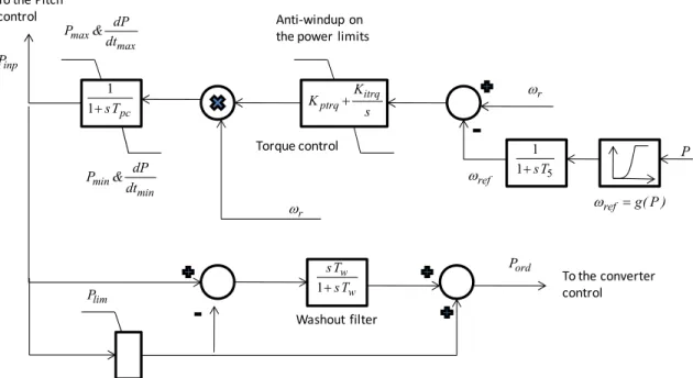
The actual electrical output power, measured at the grid terminals of the wind turbine, is added to the total power losses (mechanical and electrical) and
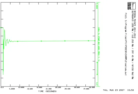
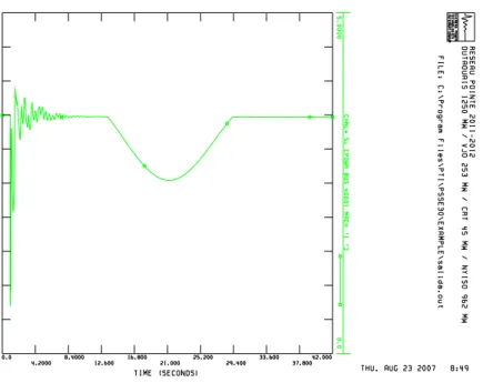
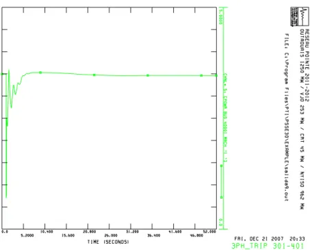
Simulations using the NREL FAST code on a 1.5-MW wind turbine are carried-out to evaluate ride-through performance of the proposed HOSM control strategy in case of grid frequency
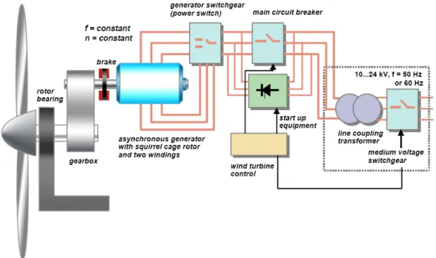
The PCS for grid connection of the PMG-based system requires a rectifier, boost converter and a grid-tie inverter, while the WRIG-based system employs a rectifier, a chopper
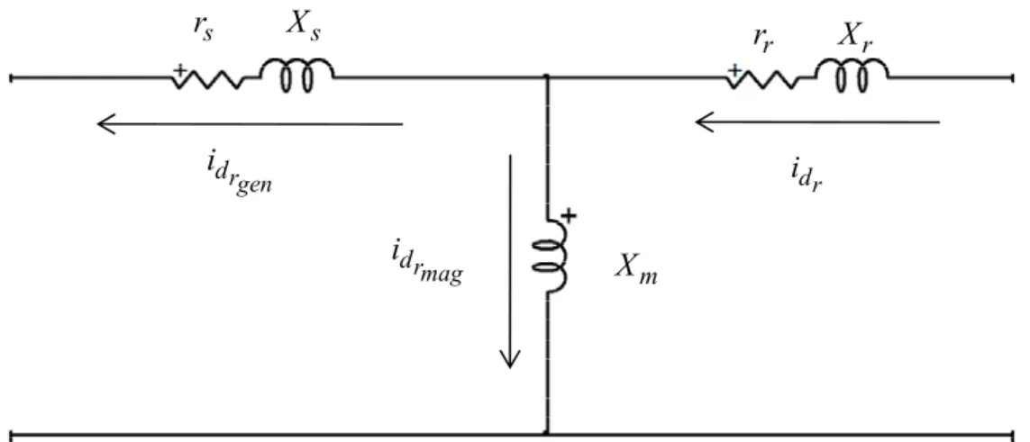
The rotor currents (which are linked to active and reactive powers by equation (16), quadrature rotor current K Q[ linked to stator active power I and direct rotor
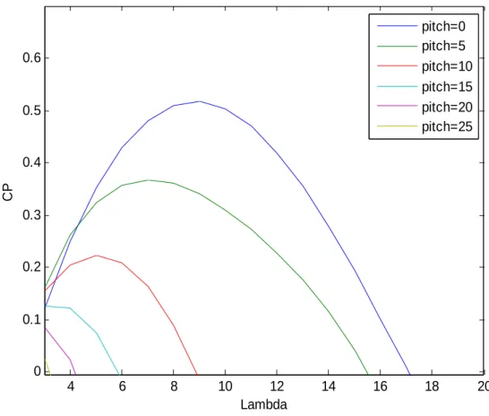
This control strategy, based on stator flux orientation, tracks the maximum power for different wind speeds, and regulates separately the active and reactive
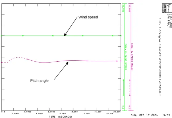
The control objective is twofold: (i) tracking the maximum available wind power; (ii) regulating the DFIG reactive power. The rotor speed, aerodynamic torque and
In the second part of this work we have assembled feasibility to monitoring and detecting the stator short-circuit fault between turns in a DFIG and open stator phases by
