HAL Id: tel-02149692
https://pastel.archives-ouvertes.fr/tel-02149692
Submitted on 6 Jun 2019HAL is a multi-disciplinary open access archive for the deposit and dissemination of sci-entific research documents, whether they are pub-lished or not. The documents may come from teaching and research institutions in France or abroad, or from public or private research centers.
L’archive ouverte pluridisciplinaire HAL, est destinée au dépôt et à la diffusion de documents scientifiques de niveau recherche, publiés ou non, émanant des établissements d’enseignement et de recherche français ou étrangers, des laboratoires publics ou privés.
entraînements électriques polyphasés : commande en
mode instantané (DTC et MPC) dans des situations
limites
Mario Bermudez Guzman
To cite this version:
Mario Bermudez Guzman. Nouvelles techniques de commande pour les entraînements électriques polyphasés : commande en mode instantané (DTC et MPC) dans des situations limites. Energie électrique. Ecole nationale supérieure d’arts et métiers - ENSAM; Universidad de Sevilla (Espagne), 2018. Français. �NNT : 2018ENAM0061�. �tel-02149692�
Arts et Métiers ParisTech - Campus de Lille
Laboratoire d’Electrotechnique et d’Electronique de Puissance de Lille
2018-ENAM-0061
École doctorale n° 432 : Science des Métiers de l’ingénieur
présentée et soutenue publiquement par
Mario BERMÚDEZ GUZMÁN
le 21 Décembre 2018Novel Control Techniques in Multiphase Drives:
Direct Control Methods (DTC and MPC) Under Limit Situations
Doctorat ParisTech
T H È S E
pour obtenir le grade de docteur délivré par
l’École Nationale Supérieure d'Arts et Métiers
Spécialité “ Génie Electrique ”
Directeur de thèse : Xavier KESTELYN
Codirecteur de cotutelle de la thèse : Federico José BARRERO GARCÍA
T
H
È
S
E
JuryMme. Betty LEMAIRE-SEMAIL, Professeur des universités, L2EP, Université Lille1 Président
M. Radu BOJOI, Full Professor, PEIC, Politecnico di Torino Rapporteur
M. Humberto HENAO, Professeur des universités, LTI, Université de Picardie Jules Verne Rapporteur
Mme. Inmaculada PLAZA GARCÍA, Associate Professor, EDUQTECH, Universidad de Zaragoza Examinateur
M. Xavier KESTELYN, Professeur des universités, L2EP, Arts et Métiers – Campus de Lille Examinateur
M. Federico José BARRERO GARCÍA, Full Professor, ACE-TI, Universidad de Sevilla Examinateur
A mi abuelo Antonio, que no pudo disfrutar del final de este trayecto.
I
Acknowledgments
This Thesis is the result of three years of work in three different institutions, research groups and countries, which has allowed me to grow professionally and personally. At the end of this stage, I would like to thank all the people who have accompanied me throughout this journey.
I shall start with my Thesis supervisors, who guided me to bring out my best and reach my potential. It has been a real pleasure, Xavier, and I am deeply grateful for providing me the opportunity to make the Thesis in Lille within the L2EP, for taking your time to help me and always giving me your good advice.
Federico, thank you for all your patience with me and for taking me on the right way when I was lost. You are willing to help 24 hours a day, 7 days a week, and this is a rara avis in the world of supervisors. However, at the end, I do not see you like a supervisor, but like a friend. I will never forget your dedication, support and help during these years.
Of course, I cannot miss this opportunity to thank the person who introduced me in the world of research, because all started with you, Mario. I will always appreciate the trust you placed in me, not only five years ago, but also now, since I am back to my origins to work with you again.
I would like to continue by sincerely thanking Mrs. Lemaire-Semail, Mr. Bojoi, Mr. Henao and Mrs. Plaza for being in my Thesis dissertation as members of the committee. I appreciated all your questions, as well as your positive remarks and comments, which made me feel satisfied with my work.
Thanks to the colleagues of ENSAM. A special mention goes to Julián, who saved my life in Lille and without him this experience would have been a little more difficult. Thanks also to Voja for our basketball games that gave me the moments of relaxation to recharge my batteries; to Ky and François for their help with the laboratory classes; and to all the people who played football on Wednesdays: Moez, Fred, Gil, Haibo, Hicham…
I will never forget the invaluable help and support of Ignacio and Hugo. We started together in the lab 3.507-II in Málaga, creating an outstanding working atmosphere that allowed us to reach all the goals. Both are brilliant researchers and, most importantly, excellent people and true friends. Thanks also to the colleagues of ACE-TI in Seville: Dani, Jesús, Jorge, José Manuel and Mario; and to the ones in Málaga: Ángel, Juanjo, Paula and Pedro. With all of them I have shared good moments throughout these three years (lunches, coffees, laughs…).
It has been an honor and a privilege to work three months in Liverpool under the supervision of Professor Levi, a true eminence in the field of multiphase drives with magnificent human qualities. My thanks are also extended to his research team: Obrad, Ahmad, Marko and Ornella.
Thanks to my lifelong friends in Málaga: Adri, Andrés, José and Juani, who have been (and will be) fundamental pillars since the beginning up until the end. In my spare time, there they are, ready to share together unforgettable experiences. Trips, games, races, beers, fitness barbecues,
II
alitoides and palmeritas, are just examples of the countless moments we lived since we met in the
school. Thanks to all of you for giving meaning to the word “friendship”.
Thanks to Mum, Dad, my brother Carlos and my sister Marta, as well as to the rest of my family, for being there whenever I needed it. They have always supported me and encouraged me during these years.
And finally, I save the best for the last. Thank you, Cristina, for giving me the strength in the bad moments, for leaving your work aside only to focus on me and for being the best partner that one could wish. Remember that you are the next to finish, but do not be worried because I will be there for you.
III
Table of Contents
Acknowledgments I
Table of Contents III
Nomenclature VII
List of Figures XIII
List of Tables XIX
1 Introduction 1
1.1 Scientific context ...1
1.2 Objectives ...2
1.3 Position of the Doctoral Thesis ...2
1.4 Document organization ...4
1.5 List of publications derived from this work ...4
2 State of the Art of Multiphase Drives 7 2.1 Historical review of multiphase drives ...7
2.2 Modeling of multiphase drives ...9
2.2.1 Multiphase machines with one frequency-domain subspace: distributed winding induction machine case ...9
2.2.2 Five-phase distributed winding induction machine: a case study ...24
2.2.3 Extension to multiphase machines with two frequency-domain subspaces: a second case example using the five-phase concentrated winding induction machine ...26
2.2.4 Multiphase machines with two frequency-domain subspaces: a third case example using the five-phase permanent magnet synchronous machine ...29
2.2.5 Modeling of the multiphase power converter ...32
2.3 State of the art in the multiphase drives control field ...38
2.3.1 Field Oriented Control ...38
2.3.2 Direct Torque Control ...41
2.3.3 Model-based Predictive Control ...48
2.4 Performance limits ...52
IV
2.4.2 Electrical limits in the control strategy ...57
2.5 Review on graphical formalisms for control ...59
2.6 Chapter conclusions ...63
3 Controller with one Frequency-Domain Subspace: The DTC Case 65 3.1 Modeling of an open-phase fault situation ...66
3.2 DTC scheme in open-phase fault operation ...67
3.3 Simulations of the open-phase fault operation using DTC ...70
3.4 Experimental validation in a real test rig ...74
3.5 A comparative analysis using conventional RFOC methods ...80
3.5.1 RFOC techniques in open-phase fault operation ...81
3.5.2 Simulation results ...83
3.5.3 Experimental assessment ...86
3.6 Chapter conclusions ...92
4 Controller with two Independent Frequency-Domain Subspaces: The MPC Case 95 4.1 Electrical constraints for the optimal control strategy ...96
4.2 Definition of an optimal controller using MPC techniques ...97
4.3 Validation of the two-stage MPC method ...101
4.3.1 Case example #1: five-phase PMSM drive ...101
4.3.2 Case example #2: five-phase concentrated winding IM drive ...111
4.4 Chapter conclusions ...118
5 Conclusions and Future Research 119 5.1 Conclusions ...119
5.2 Future research ...120
6 Résumé étendu en français 123 6.1 Contexte scientifique ...123
6.2 Objectifs ...124
6.3 Positionnement de la thèse ...125
6.4 Organisation du document ...126
6.5 Etat de l’art des entraînements polyphasés ...127
6.6 Contrôleur avec un unique sous-espace à contrôler dans le domaine fréquentiel : cas de la DTC ...128
6.7 Contrôleur avec deux sous-espaces indépendants à contrôler dans le domaine fréquentiel : cas de la MPC ...130
6.8 Conclusions ...131
7 Resumen extenso en español 133 7.1 Contexto científico ...133
V
7.2 Objetivos ...134
7.3 Posicionamiento de la Tesis Doctoral ...135
7.4 Organización del documento ...136
7.5 Estado del arte de los accionamientos multifásicos ...137
7.6 Controlador con un único subespacio a controlar en el dominio de frecuencia: caso del DTC ...138
7.7 Controlador con dos subespacios independientes a controlar en el dominio de frecuencia: caso del MPC ...139
7.8 Conclusiones ...141
Bibliography i Appendices xv A Discrete-Time State-Space Models xvii A.1 Five-phase induction machine with distributed windings ... xvii
A.2 Five-phase induction machine with concentrated windings ...xx
A.3 Five-phase permanent magnet synchronous machine ...xxv
B Flux and Torque Estimators for DTC xxix B.1 Healthy operation ... xxix
B.2 Post-fault operation ...xxx
C Electrical and Mechanical Parameters xxxi C.1 Five-phase IM drive with distributed windings ... xxxi
C.2 Five-phase PMSM drive ... xxxi
VII
Nomenclature
Abbreviations and acronyms
AC Alternating Current
ACE-TI Cybernetics Applications of Electronics for Information Technology CBPWM Carrier Based Pulse Width Modulation
CCS-MPC Continuous-Control-Set Model-based Predictive Control CPU Central Processing Unit
CW-IM Concentrated Winding Induction Machine DC Direct Current
DRFOC Direct Rotor Flux Oriented Control DSP Digital Signal Processor
DTC Direct Torque Control
DW-IM Distributed Winding Induction Machine EMF Electromotive Force
EMR Energetic Macroscopic Representation
FCS-MPC Finite-Control-Set Model-based Predictive Control FOC Field Oriented Control
FPGA Field-Programable Gate Array GPIO General Purpose Input/Output GVF Generalized Vectorial Formalism HDL Hardware Description Language HM Homopolar Machine
IGBT Insulated-Gate Bipolar Transistor IM Induction Machine
IRFOC Indirect Rotor Flux Oriented Control
L2EP Laboratoire d’Electrotechnique et d’Electronique de Puissance de Lille MCL Minimum Copper Loss
MM Main Machine
MMF Magnetomotive Force
MPC Model-based Predictive Control
MT Maximum Torque
PC Personal Computer
PCC Predictive Current Control PI Proportional Integral
VIII PMSM Permanent Magnet Synchronous Machine PR Proportional Resonant
PWM Pulse Width Modulation RFOC Rotor Field Oriented Control RMS Root Mean Square
SM Secondary Machine
ST-DTC Switching Tables Direct Torque Control
SVM-DTC Space Vector Modulated Direct Torque Control SVPWM Space Vector Pulse Width Modulation
US University of Seville
VHDL VHSIC Hardware Description Language VHSIC Very High Speed Integrated Circuits VSD Vector Space Decomposition
VSI Voltage Source Inverter
Variables, parameters, matrices and vectors
[A] Input matrix for the discrete-time state-space model [B] State matrix for the discrete-time state-space model [Bc] Constant elements of matrix [B]
Bm Friction coefficient of the rotor-load bearings
[Bωa] Elements of matrix [B] that depend on the instantaneous values of ωa
[Bωr] Elements of matrix [B] that depend on the instantaneous values of ωr
[C], [d], [E] Matrices for the constraints in the optimization problem expressed in the quadratic programming form
[C5] 5-phase Clarke transformation matrix
[Cn] n-phase Clarke transformation matrix
[Cn-m] Reduced-order Clarke transformation matrix
[CPOST] Clarke transformation matrix in post-fault situation
[D] Constant matrix for the discrete-time state-space model
dT Output of the torque hysteresis comparator
dλ Output of the flux hysteresis comparator
dω Output of the speed hysteresis comparator
d–q Subspace in the rotating reference frame
e Feedforward term for the FOC scheme
F Objective function for the optimization problem
FQP Objective function for the optimization problem expressed in the quadratic
programming form
f Frequency
f1 Frequency of the fundamental component H Air-gap magnetic field
IX
[H] Quadratic part of the objective function for the optimization problem expressed in the quadratic programming form
[h] Linear part of the objective function for the optimization problem expressed in the quadratic programming form
[I] Identity matrix for the discrete-time state-space model
i Current
[I5] Identity matrix of order 5
[iabcde] Stator phase currents vector
[ibcde] Stator phase currents vector in post-fault situation Imax Maximum peak value between all phase currents
IM,max Maximum magnetizing current value
[In] Identity matrix of order n
[ir] Rotor currents vector (referred to the stator)
[i′r] Rotor currents vector (real rotor components)
IRMS Maximum RMS phase current value established by the copper losses
[is] Stator currents vector
Isd,rated Rated magnetizing current value
Isn Nominal stator current value
IVSI Maximum peak phase current value imposed by the VSI J Cost function for MPC
J0 Initial value of J
Jm Rotational inertia of the machine k Time instant (present)
k + 1 Time instant (future)
Ki Integral parameter for PI and PR controllers Kp Proportional parameter for PI and PR controllers Kv1, Kv2 Dwell time ratios that define the virtual voltage vector kw Transformation ratio in the stator-rotor coupling, kw = Ns/Nr Llr Rotor leakage inductance
Lls Stator leakage inductance
Lm Mutual inductance in the stationary/rotating reference frame, Lm = (n/2)·M Lr Rotor inductance, Lr = Llr + Lm
[Lrr] Matrix including the self- and mutual inductances of the rotor phases
[Lrs(θ)] Matrix including the mutual inductances in the coupling rotor-stator Ls Stator inductance, Ls = Lls + Lm
[Lsr(θ)] Matrix including the mutual inductances in the coupling stator-rotor
[Lss] Matrix including the self- and mutual inductances of the stator phases M Mutual inductance
[M] Null space of [C]
m Number of phases in open-circuit
[Mrr(ϑ)] Matrix that defines the mutual inductances in [Lrr]
X
[Mss(ϑ)] Matrix that defines the mutual inductances in [Lss] n Arbitrary number of phases
Np Prediction horizon Nr Rotor windings turns Ns Stator windings turns p Pairs of poles
[Pr5] 5-phase rotation matrix for rotor variables (from stationary to rotating reference
frames)
[Prn] n-phase rotation matrix for rotor variables (from stationary to rotating reference
frames)
[Ps5] 5-phase rotation matrix for stator variables (from stationary to rotating reference
frames)
[Psn] n-phase rotation matrix for stator variables (from stationary to rotating reference
frames)
QET Torque quadratic error, QET = (T*em – Tem)2
QI Quadratic stator current, QI = isd12 + isq12 + isd32 + isq32 Rr Rotor resistance (referred to the stator), Rr = kw2·R′r
[Rr] Matrix of rotor resistances R′r Rotor resistance (real value) Rs Stator resistance
[Rs] Matrix of stator resistances S State of each VSI leg (1 or 0)
[S] Switching state vector, [S] = [Sa Sb Sc Sd Se]T
[S0] Zero switching state vector, [S0] = [0 0 0 0 0]T
[Sn] One of the available switching state vectors
[Sopt] Optimum switching state vector
sync Synchronization signal in OPAL-RT
t Time
[T5] 5-phase extended Park matrix (from phase to rotating reference frames) Tem Electromagnetic torque
TL Load torque
Tn Nominal torque
[Tr(θ)] Rotation matrix for rotor variables (from rotor to stationary reference frames)
Ts Sampling time
[U] Input vector for the discrete-time state-space model
u Phase-to-phase voltage
v Voltage
[vabcde] Stator phase voltages vector
[vbcde] Stator phase voltages vector in post-fault situation vcm Common-mode voltage
Vdc DC-link voltage vLong Long voltage vector
XI
Vmax Maximum peak value between all phase-to-phase voltages
vMedium Medium voltage vector
vN Voltage between the negative DC-link bus and the common point of the star
connection in the VSI
[vr] Rotor voltages vector (referred to the stator)
[v′r] Rotor voltages vector (real rotor components)
[vs] Stator voltages vector
vShort Short voltage vector
VVi Virtual voltage vector VVLi Long virtual voltage vector VVSi Short virtual voltage vector Wco Magnetic coenergy
[X] State variables vector for the discrete-time state-space model [x] Dual optimization variable for the quadratic programming problem
[xopt] Optimal solution of the dual optimization variable in the quadratic
programming problem
x–y Secondary orthogonal subspace in the stationary reference frame
z Homopolar component axis
[z] Primal optimization variable for the quadratic programming problem
α–β Main orthogonal subspace in the stationary reference frame
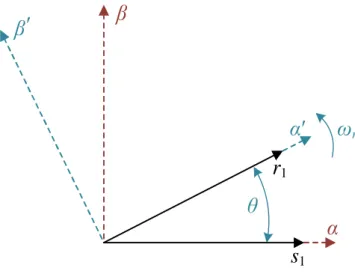
α′–β′ Rotor reference frame
[Γ], [Ψ], [Φ] Discretized matrices for the discrete-time state-space model
γ Load angle (i.e. between stator and rotor flux vectors)
δ Slip coordinate (i.e. between rotating and rotor reference frames) Δk Angle that defines matrix [Δ(θ)]
ΔTem Torque hysteresis band ε Speed-normalized back EMF
η Ratio between the weighting factors, η = κT/κi
θ Coordinate of the rotor with respect to the stationary reference frame
θa Coordinate of the rotating reference frame with respect to the stationary one ϑ Electrical displacement between stator windings
κi Weighting factor related to the minimization of the copper losses κT Weighting factor related to the reference torque tracking
λ Flux
λm Amplitude of the flux linkage due to the permanent magnets in PMSM
[λm] Flux linkage matrix due to the permanent magnets in PMSM
[λr] Rotor fluxes vector (referred to the stator)
[λ′r] Rotor fluxes vector (real rotor components)
[λs] Stator fluxes vector
μ Electrical variable (voltage, current or flux)
[μr] Rotor electrical variables vector (voltage, current or flux)
XII
σ, τls Constants for the discrete-time state-space model τr Rotor time constant, τr = Lr/Rr
τs Stator time constant, τs = Ls/Rs
φ Angle considered in the expression of IM,max ωa Rotating reference frame speed
ωm Mechanical speed of the rotor shaft
ωmth Low-speed threshold for the DTC controller
ωr Rotor electrical speed (i.e. rotor reference frame speed) ωsl Slip speed
Subscripts
1 Related to the fundamental component 3 Related to the third harmonic component
a… e Related to the phases ‘a’… ‘e’ of the 5-phase machine
d Related to the d-axis of the rotating reference frame max Maximum value of a variable
q Related to the q-axis of the rotating reference frame r Related to the rotor
s Related to the stator
x Related to the x-axis of the stationary reference frame y Related to the y-axis of the stationary reference frame z Related to the homopolar component
α Related to the α-axis of the stationary reference frame β Related to the β-axis of the stationary reference frame Superscripts
k Present value of a variable (time instant k) k+1 Future value of a variable (time instant k + 1) T Transposition operation
* Reference variable ^ Estimated variable
XIII
List of Figures
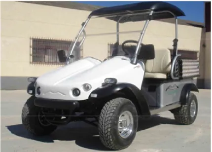
Figure 1.1. Prototype of the electric vehicle that belongs to ACE-TI. ...3
Figure 2.1. Schematic of the symmetrical n-phase induction machine. ...10
Figure 2.2. Reference frames of stator (α–β) and rotor (α′–β′) variables. ...17
Figure 2.3. Rotating reference frame (d–q). ...21
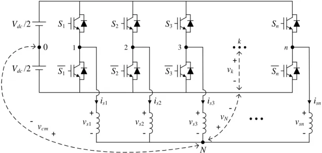
Figure 2.4. Schematic diagram of the n-leg two-level VSI. ...33
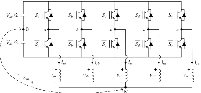
Figure 2.5. Five-leg two-level VSI with star-connected load. ...36
Figure 2.6. Five-leg two-level VSI load configuration scheme. ...36
Figure 2.7. Mapping of the phase voltages of the five-leg VSI into the α–β (left plot) and x– y (right plot) planes. ...37
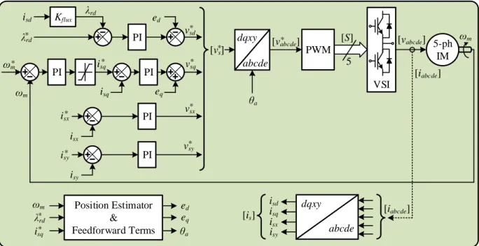
Figure 2.8. IRFOC control scheme applied to a five-phase IM with distributed windings. ...40
Figure 2.9. Impact of a voltage vector on both the stator flux and the load angle. (a) Phasor diagram of the real model of the machine. (b) Estimated phasor diagram for the application of DTC. ...43
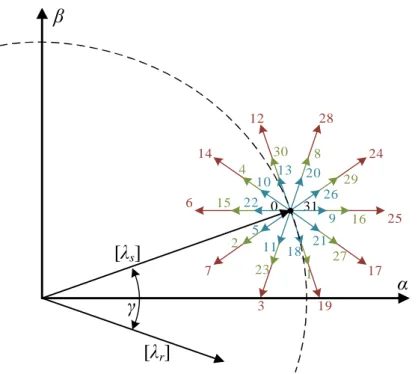
Figure 2.10. Diagram of the flux vectors together with the spatial voltage vectors available for the control. ...44
Figure 2.11. VVL1 projections in the (a) α–β and (b) x–y planes. ...45
Figure 2.12. Virtual voltage vectors in the α–β plane. ...45
Figure 2.13. DTC scheme applied to a five-phase IM with distributed windings. ...47
Figure 2.14. Model-based Predictive Control methods. ...48
Figure 2.15. FCS-MPC control scheme. ...50
Figure 2.16. Flow diagram of the FCS-MPC method. ...51
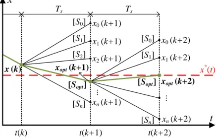
Figure 2.17. FCS-MPC prediction horizon principle. ...52
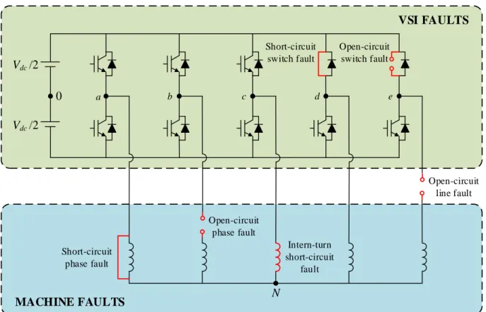
Figure 2.18. Schematic of different types of faults in a five-phase drive. ...54
Figure 2.19. Inversion-based control principle. ...59
XIV
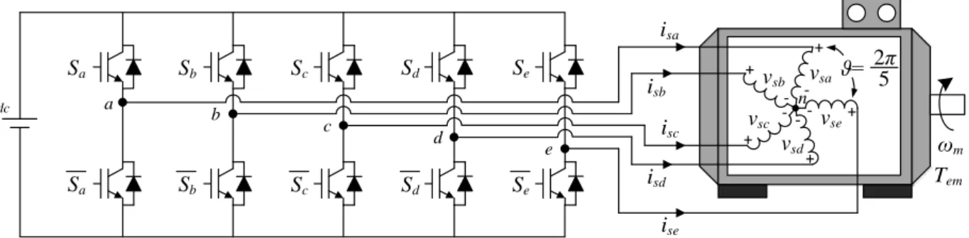
Figure 2.21. EMR for a five-phase PMSM. ...61 Figure 2.22. Practical control scheme for a five-phase PMSM. ...63 Figure 3.1. Schematic diagram of the five-phase IM drive. ...66 Figure 3.2. Available voltage vectors in the α–β (left plot) and x–y (right plot) planes in open-phase fault operation. ...68 Figure 3.3. Virtual voltage vectors (VVi) in the α–β subspace during open-phase fault
operation. ...69 Figure 3.4. DTC scheme regulating five-phase IM drives in open-phase fault situation. The ‘^’ and ‘*’ symbols identify the estimated and reference variables, respectively. ...70 Figure 3.5. Simulation of the steady-state operation in post-fault mode of a 5-phase DW-IM drive. The reference speed is settled at 500 rpm. (a) Speed response. (b) Zoomed-in stator phase currents. (c) Zoom-in of the estimated and obtained stator flux waveforms. (d) Current trajectories in the α–β and x–y planes. ...71 Figure 3.6. Simulation reversal test during the post-fault operation of a 5-phase DW-IM drive. A change in the reference speed from 500 to –500 rpm is applied. (a) Speed response. (b) Stator phase current and (c) stator flux waveforms in the α–β plane during the zero-speed crossing operating point. ...72 Figure 3.7. Simulation of the transition from pre- to post-fault operation of a 5-phase DW-IM drive. The fault appearance is at t = 0.2 s. (a) Speed response. Zoomed-in (b) phase, (c)
α–β and (d) x–y currents before (t < 0.2 s) and after (t > 0.2 s) the fault occurrence. ...73
Figure 3.8. Graphical scheme of the experimental test rig based on a symmetrical five-phase distributed winding IM drive. ...74 Figure 3.9. Experimental test of the speed step response for a 5-phase DW-IM drive. The reference speed is changed from 0 to 500 rpm at t = 0.1 s, while no load torque condition is assumed. (a) Speed response. (b) Estimated electrical torque. (c) Estimated stator flux in the
α–β plane. ...75
Figure 3.10. Experimental speed reversal test for a 5-phase DW-IM drive. The reference speed is changed from 500 to –500 rpm at 0.2 s. (a) Speed and (b) torque reference tracking. (c) Stator currents in the α–β plane at the zero-speed crossing point. ...76 Figure 3.11. Experimental load torque rejection test for a 5-phase DW-IM drive. A change from 0 to 50% of the nominal load torque is applied at t = 1.1 s. (a) Speed response. (b) Estimated electrical torque behavior. Stator current performance in α–β and x–y planes in steady state with (c) null and (d) 50% of the nominal torque, respectively. ...77 Figure 3.12. Experimental test of the transition from pre- to post-fault operation of a 5-phase DW-IM drive considering instantaneous control reconfiguration when the fault appears at t = 0.2 s. A reference speed of 500 rpm is assumed with an applied load torque of (a) 28%, (b) 50% and (c) 70% of the nominal one. The speed and estimated torque response is depicted in left and right plots, respectively. ...78 Figure 3.13. Healthy stator phase currents from the current probes when the open-phase fault appears in a 5-phase DW-IM drive and instantaneous control reconfiguration is used.
XV
The applied reference speed is 500 rpm and the demanded load torque is about 50% of the nominal one. ...79 Figure 3.14. Experimental test of the low-speed operation of the 5-phase DW-IM drive. The reference speed is set to 50 rpm, while load torques of (a) 28% and (b) 50% of the nominal one are applied. The speed response and the estimated electrical torque are depicted in left and right plots, respectively. The fault is forced at t = 0.2 s. ...80 Figure 3.15. RFOC scheme based on PR (upper plot) and PCC (bottom plot) controllers. ...82 Figure 3.16. Simulation performance comparison of the steady-state operation of a 5-phase DW-IM drive, with a reference speed of 500 rpm and a load torque of about 25% of the nominal one. Stator phase currents (left-hand side plots) and evolution in the α–β (middle plots) and x–y (right-hand side plots) planes, implementing (a) PR, (b) PCC and (c) DTC controllers, respectively. ...83 Figure 3.17. Simulation performance comparison of the steady-state operation of a 5-phase DW-IM drive, with a reference speed of 500 rpm and a load torque of about 50% of the nominal one. Stator phase currents (left-hand side plots) and evolution in the α–β (middle plots) and x–y (right-hand side plots) planes, implementing (a) PR, (b) PCC and (c) DTC controllers, respectively. ...84 Figure 3.18. Simulation performance comparison when the reference speed is changed in a 5-phase DW-IM drive using a load torque of about 25% of the nominal one. (a) Speed response. (b) Zoom-in of the speed tracking. ...85 Figure 3.19. Simulation performance comparison of the speed response if a reversal test from 500 to –500 rpm is carried out in a 5-phase DW-IM drive. ...85 Figure 3.20. Simulation performance comparison of the generated electrical torque in a 5-phase DW-IM drive when the load torque is changed from 0% to 25% of the nominal one. The reference speed is maintained at 500 rpm during the test. ...86 Figure 3.21. Experimental performance comparison of the steady-state faulty operation of a 5-phase DW-IM drive. The reference speed is set to 500 rpm and a load torque of 28% of the nominal one is required. Stator phase currents obtained from the current probes and stator phase currents in α–β and x–y planes (left and right plots, respectively), while (a) PR, (b) PCC and (c) DTC controllers are used. ...87 Figure 3.22. Experimental performance comparison of the steady-state faulty operation of a 5-phase DW-IM drive. The reference speed is set to 500 rpm and a load torque of 56% of the nominal one is required. Stator phase currents obtained from the current probes and stator phase currents in α–β and x–y planes (left and right plots, respectively), while (a) PR, (b) PCC and (c) DTC controllers are used. ...88 Figure 3.23. Experimental comparison of the dynamic performance of a 5-phase DW-IM drive in faulty operation. The reference speed is changed from 500 to –500 rpm at t = 0.2 s, while no electrical load torque is demanded. Speed response and stator current waveforms in the α–β plane at the zero-speed crossing point (left and right plots, respectively), when (a) PR, (b) PCC and (c) DTC controllers are used. ...89 Figure 3.24. Experimental performance comparison of the pre- to post-fault transition under realistic conditions (a delay of 40 ms in the fault detection is assumed) in a 5-phase DW-IM
XVI
drive. A load torque of about 50% of the nominal one and a reference speed of 500 rpm are used. Speed response and zoom-in of the generated electrical torque at the fault occurrence instant (left and right plots, respectively), when (a) PR, (b) PCC and (c) DTC techniques are considered. ...90 Figure 3.25. Experimental performance comparison of the pre- to post-fault transition at low-speed operation of a 5-phase DW-IM drive, where a delay of 40 ms in the fault detection process is assumed. A load torque of about 50% of the nominal one and a reference speed of 50 rpm are used. Speed response and generated electrical torque (left and right plots, respectively), when considering (a) PR, (b) PCC and (c) DTC techniques. ...91 Figure 4.1. Scheme of the proposed optimal controller. ...97 Figure 4.2. First MPC stage to implement the proposed technique: optimization process for the reference current generation. ...99 Figure 4.3. Second MPC stage to implement the proposed technique: FCS-MPC inner current controller. ...100 Figure 4.4. Block diagram of the second control stage based on the FCS-MPC method. ...101 Figure 4.5. Description of the proposed technique in a real-time system based on OPAL-RT technologies for the case example #1. ...102 Figure 4.6. General architecture of the five-phase PMSM real-time model simulator in FPGA. ...103 Figure 4.7. Computation timeline of the simulation model in the real-time system. ...104 Figure 4.8. Extended Park matrix generator in the real-time system. ...105 Figure 4.9. Evaluation of the dimensionless QI and QET terms using different η values when the PMSM is driven at a particular operating point (50 rad/s and 10 N-m). ...106 Figure 4.10. Real-time simulation for the steady-state analysis of the 5-phase PMSM drive, including a speed ramp test where the speed is varied in the machine from 0 rad/s to 240 rad/s and the reference torque is higher than the maximum value. (a) Obtained electrical torque versus speed characteristic of the system. (b) Evolution of dq1 and dq3 stator current
values. ...107 Figure 4.11. Real-time simulation of the steady-state operation of the 5-phase PMSM drive in cases 1 and 2: operation without considering voltage or current limits (left plots) and considering the current limit (right plots). (a) Stator phase current. (b) Filtered phase-to-phase stator voltages. ...109 Figure 4.12. Real-time simulation of the steady-state operation of the 5-phase PMSM drive in cases 3 and 4: operation considering a voltage limit (left plots) and taking into account current and voltage limits (right plots). (a) Stator phase current. (b) Filtered phase-to-phase stator voltages. ...109 Figure 4.13. Real-time simulation of the dynamic response of the 5-phase PMSM drive using the proposed technique under current and voltage limits. The reference torque is changed from 0 to 20 N-m (at t = 0.01 s approximately), while the machine operates at 150
XVII
rad/s (above the base speed). (a) Torque response. (b) Evolution in dq1 and dq3 stator
currents. ...110 Figure 4.14. Evaluation of the dimensionless QI and QET terms using different η values when the 5-phase CW-IM is driven at a particular operating point (20 rad/s and 6 N-m). ...111 Figure 4.15. Experimental test for the steady-state analysis of the proposed controller using a 5-phase CW-IM drive. (a) Maximum obtained electrical torque versus speed. (b) Maximum phase-to-phase stator voltage and phase stator current (normalized to their limit values, Vdc and IVSI, respectively). (c) Stator currents in d1- and d3-axes. (d) Stator currents
in q1- and q3-axes. ...113
Figure 4.16. Maximum electrical torque in the experimental system based on the 5-phase CW-IM drive with and without the injection of third harmonic stator current components. ...113 Figure 4.17. Experimental test of the 5-phase CW-IM drive when the maximum load torque is applied at a reference speed of 20 rad/s. (a) Measured mechanical speed versus the applied reference. (b) Obtained electrical torque. (c) Stator currents in d1- and d3-axes. (d) Stator
currents in q1- and q3-axes. (e) Stator phase current ‘a’. (f) Time-domain performance and
frequency spectrum of phase-to-phase voltage uac. ...114
Figure 4.18. Experimental test of the 5-phase CW-IM drive when the maximum load torque is applied at a reference speed of 60 rad/s. (a) Measured mechanical speed versus the applied reference. (b) Obtained electrical torque. (c) Stator currents in d1- and d3-axes. (d) Stator
currents in q1- and q3-axes. (e) Stator phase current ‘a’. (f) Time-domain performance and
frequency spectrum of phase-to-phase voltage uac. ...115
Figure 4.19. Experimental test of the dynamic response of the 5-phase CW-IM drive for a reference speed of 20 rad/s and a load torque step from 6.4 N-m to 8.13 N-m. (a) Measured mechanical speed versus the applied reference. (b) Obtained electrical torque. (c) Stator currents in d1- and d3-axes. (d) Stator currents in q1- and q3-axes. (e) Stator phase current
‘a’. (f) System evolution in the maximum torque-speed curve. ...116 Figure 4.20. Experimental test of the dynamic response of the 5-phase CW-IM drive for a speed step from 40 to 60 rad/s and a load torque equal to 6.4 N-m (the maximum available at 60 rad/s). (a) Measured mechanical speed versus the applied reference. (b) Obtained electrical torque. (c) Stator currents in d1- and d3-axes. (d) Stator currents in q1- and q3-axes.
(e) Stator phase current ‘a’. (f) System evolution in the maximum torque-speed curve...117 Figure 6.1. Prototype du véhicule électrique appartenant à ACE-TI. ...126 Figura 7.1. Prototipo del vehículo eléctrico perteneciente a ACE-TI. ...135
XIX
List of Tables
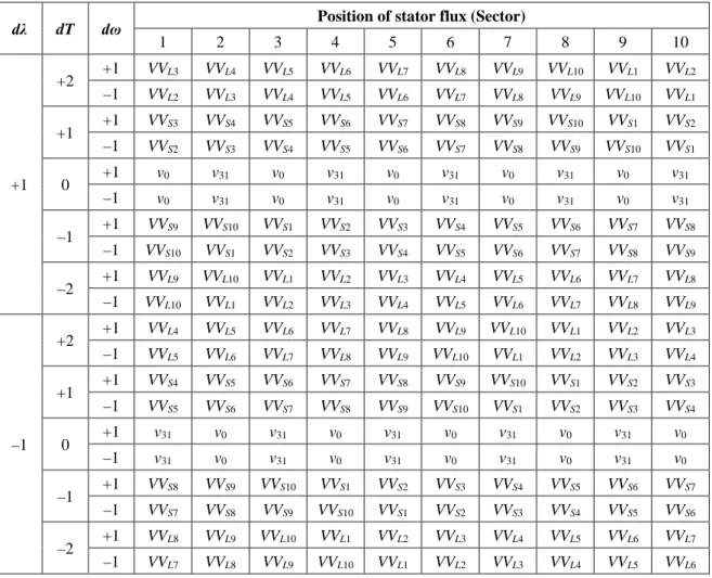
Table 2.1. Look-up table for the DTC controller ...47 Table 3.1. Dwell times during the open-phase fault operation. ...69 Table 3.2. Look-up table for the DTC controller in post-fault situation. ...69 Table 3.3. Proportional and integral parameters of PI and PR controllers. ...86 Table 3.4. Qualitative comparison between RFOC and DTC methods in open-phase fault operation. ...92 Table 4.1. A representative set of obtained QI and QET curves in terms of their crossing points at different working conditions for case example #1. ...106 Table 4.2. Analyzed steady-state reference points in Figs. 4.11 and 4.12. ...108 Table 4.3. A representative set of obtained QI and QET curves in terms of their crossing points at different working conditions for case example #2. ...112 Table 5.1. Summary of the internationalization derived from this Doctoral Thesis ...120 Tableau 6.1. Résumé de l’internationalisation résultant de cette thèse ...132 Tabla 7.1. Sumario de la internacionalización derivada de esta Tesis Doctoral ...142 Table C.1. Electrical and mechanical parameters of the five-phase DW-IM drive. ... xxxi Table C.2. Parameters of the five-phase PMSM drive and considered limits. ... xxxi Table C.3. Parameters of the five-phase CW-IM drive and considered limits. ... xxxii
1
Chapter 1
Introduction
1.1 Scientific context
The use of electrical drives in embedded systems instead of conventional engines has grown in recent times. This is the case of electric vehicles propulsion and railway traction, all-electric ships, more-electric aircraft, and renewable energies. The specific constraints imposed to the volume of such systems and the constant necessity for higher power ratings lead to optimize the utilization of all components of the electric power train. Therefore, the rated functioning zones are shifted towards their limits, appearing in the system fault situations or nonlinear behaviors such as voltage and current limitations or magnetic saturation. As an example, the use of electrical drives for the propulsion of electric vehicles requires to control the drive in the whole speed range, including the flux-weakening region where voltage limits are reached.
Compared to classical three-phase drives, multiphase ones reduce the electrical stresses on machine and power electronic components, since they can manage more power with lower torque pulsation and lower current harmonic content, and have inherent fault-tolerance capabilities. Such advantages make them an ideal candidate for applications where limits can be reached and reliability is of special interest for economical and safety reasons. Recent research works on multiphase drives aim to exploit their special characteristics and present them to the industry as an alternative to the three-phase ones, where the higher number of phases results in higher control and design degrees of freedom that can improve the overall reliability and performance of the system.
Consequently, control techniques have been proposed in recent times for multiphase drives, which usually are an extension of the conventional three-phase control structures, aiming for the high speed/torque performance of the drive. Nevertheless, there still exists a lack of research with regard of limit situations that can occur in the machine. If the system works below its limits, it is possible to decompose the system into several subspaces that are independently controlled (‘average control’). However, in the case of a system working close to its limits, it is no more possible and a direct control of the whole system is necessary. The main difficulty comes from the way to formalize the problem in order to be able to take into account the constraints along with respecting the given objectives.
In this context, different ‘direct control’ techniques are proposed in this Doctoral Thesis work to overcome these situations, being Direct Torque Control and Model-based Predictive Control the representatives of this type of techniques.
2
1.2 Objectives
The general objective of this Doctoral Thesis work is the development of direct control techniques to optimally control multiphase machines, studying the tolerance of the drive to different operating conditions, such as electrical limits (voltage, current and magnetization level limits) or fault tolerance (open-phase fault situation). The meaning of ‘direct control’ techniques is related to those whose control strategy is made without the intervention of a Pulse Width Modulation (PWM) stage or other form of modulation, providing control commands that are directly applied to the power converter. The direct control strategies that will be analyzed in this Thesis are the most used ones in literature, i.e. Direct Torque Control (DTC) and Model-based Predictive Control (MPC). For this purpose, the study will be focused on multiphase drives controlled using different frequency-domain control subspaces. On the one hand, five-phase induction machines with distributed windings, controlled using only one frequency-domain subspace (flux and torque in the α–β plane). On the other hand, five-phase permanent magnet synchronous machines and five-phase induction machines with concentrated windings, which have two controlled subspaces (flux and torque in the α1–β1 and α3–β3 planes). The general
objective can be divided more specifically in the following tasks:
- Research on multiphase machines, their advantages/disadvantages over the three-phase ones and their industrial applications, with regard to identify the systems limitations and constraints. Likewise, analysis of the state-of art of direct control strategies (DTC and MPC, as main representatives) to be applied in the multiphase drives control.
- Study and analysis of conventional three-phase DTC strategies and their extension to the fault tolerance case in multiphase drives, focusing on a five-phase drive with one frequency-domain subspace. For this purpose, it is necessary the implementation of new look-up tables for the control variables, with the aim of taking into account in the control strategy the encountered constraints when an open-phase fault occurs in the machine. - Comparison of the fault-tolerant capability of DTC with other control techniques, to
conclude the strengths and weaknesses of the analyzed methods facing the open-phase fault operation.
- Development of an optimal current controller using MPC techniques that allows the optimal utilization of the system’s torque capability under voltage, current and magnetic limitations. The interest of the proposed controller will be verified using five-phase machines with two frequency-domain subspaces.
1.3 Position of the Doctoral Thesis
The Doctoral Thesis work is based on an international joint supervision agreement between the École Nationale Supérieure d’Arts et Métiers (Arts et Métiers from now on) – Campus de Lille, France, and the University of Seville (US), Spain. The supervisors in each institution are Prof. Xavier Kestelyn and Prof. Federico José Barrero García, respectively, who are internationally recognized in the field of multiphase drives and have many years of experience on the topic.
3
Therefore, making the Doctoral Thesis under their co-supervision is a great opportunity to work at the best level on this field.
At Arts et Métiers, the work takes place at the Laboratoire d’Electrotechnique et d’Electronique de Puissance de Lille (L2EP) within the Control team, being Prof. Kestelyn one of its members. This team is focused on the development of modeling and control formalisms dedicated to energy conversion systems. The Energetic Macroscopic Representation (EMR) and the Generalized Vectorial Formalism (GVF) are multi-physic formalisms that allow to handle a wide field of applications, focusing currently on electrical devices, multiphase drives, piezo-electric actuators and piezo-electrical vehicles. The Control team also leads the MEGEVH network (Energetic Management and Modeling of Hybrid Vehicles), which aims to foster collaboration between academic and industrial partners on the subject of modeling and power management of hybrid vehicles.
On the other hand, Prof. Barrero has led the research group Cybernetics Applications of Electronics for Information Technology (ACE-TI) at US. The research fields of this group are, among others, electric vehicles, smart cities or wireless sensor networks. Nowadays, ACE-TI is focused on adapting a test rig for multiphase drives, which belongs to the research group, for its application in the modeling, development and management of the energy in electrical vehicles. A picture of the prototype of the electric vehicle is presented in Fig. 1.1.
Figure 1.1. Prototype of the electric vehicle that belongs to ACE-TI.
This Doctoral Thesis work is focused on what can be defined as basic research. Accordingly, different direct control methods are analyzed to establish a presented and well-defined regulation technique in multiphase drives, where electrical/magnetic limits and critical operating conditions can be managed. However, the work needs a later stage of application-oriented research, which would involve the integration of the used electromagnetic drives and control techniques for their analysis in low- and medium-power electrical systems for industry applications.
Previous Doctoral Thesis works in both institutions are related to the use of multiphase drives and constitute the background of this work.On the part of L2EP, the Doctoral Theses of Xavier Kestelyn and Paul Sandulescu must be emphasized [1–3], which were centered on the modeling
4
of the machine and its control. Additionally, the studies of Bassel Aslan, Hussein Zahr and Tiago José Dos Santos Moraes [4–6] were focused on the design of different types of multiphase machines for industrial applications. It has to be noted also the works of Li Lu [7], related to the flux-weakening operation in multiphase machines, and Ousmane Fall [8], regarding the inclusion of limits in system. Furthermore, the Doctoral Theses of Raúl Igmar Gregor Recalde, José Agustín Riveros Insfrán, Hugo Mauricio Guzmán Jiménez and Ignacio González Prieto, on the topic of the development of control strategies for multiphase drives under healthy [9, 10] and open-phase fault operation [11, 12] represent the precedent works from ACE-TI.
1.4 Document organization
This document is organized in the following way. Chapter 1 introduces the scientific context and the objectives of the present Thesis, showing the position and the background in relation with the two institutions where the work is conducted. A summary of the journal papers and conference works behind this doctoral research work is presented at the end of the chapter. Chapter 2 describes the state of the art related to the control of multiphase electrical drives. The most recent researches in the scientific literature are commented in order to emphasize the interest of this Thesis. Chapter 3 is focused on the study of the open-phase fault operation using DTC in multiphase machines with one frequency-domain subspace. An experimental assessment is also carried out comparing the performances of different control strategies, when facing the fault situation. In Chapter 4, on the other hand, the case of machines with two frequency-domain subspaces is analyzed. In this case, the DTC strategy seems insufficient to address the situation, since it only allows the control of two degrees of freedom in the system. Therefore, a novel MPC technique is presented to generate online optimal current references taking into account programmed electrical and magnetic constraints, while regulating the currents of the system in order to track the optimal references. The conclusions and the proposition of future work are gathered in Chapter 5. Finally, in Chapters 6 and 7, a comprehensive summary of the Thesis in French and Spanish, respectively, is detailed to comply with the international joint supervision agreement that supports this work.
1.5 List of publications derived from this work
The publications resulting from this Doctoral Thesis work are listed down below. The main contributions presented in this manuscript are based on the journal papers Journal I to Journal IV, as well as on the conference papers Conference I to Conference III.
- Journal I: “Open-Phase Fault-Tolerant Direct Torque Control Technique for Five-Phase Induction Motor Drives”. M. Bermúdez, I. González-Prieto, F. Barrero, H. Guzmán, M.J. Durán, X. Kestelyn. IEEE Transactions on Industrial Electronics, February 2017.
- Journal II: “An Experimental Assessment of Open-Phase Fault-Tolerant Virtual-Vector-Based Direct Torque Control in Five-Phase Induction Motor Drives”. M. Bermúdez, I. González-Prieto, F. Barrero, H. Guzmán, X. Kestelyn, M.J. Durán. IEEE Transactions on Power Electronics, March 2018.
5
- Journal III: “Model predictive optimal control considering current and voltage limitations: real-time validation using OPAL-RT technologies and five-phase permanent magnet synchronous machines”. M. Bermúdez, O. Gomozov, X. Kestelyn, F. Barrero, N.K. Nguyen, E. Semail. Mathematics and Computers in Simulation, July 2018.
- Journal IV: “Predictive controller considering electrical constraints: a case example for five-phase induction machines”. M. Bermúdez, C. Martín, F. Barrero, X. Kestelyn. IET Electric Power Applications, October 2018. UNDER REVIEW.
- Conference I: “Open-phase fault operation of 5-phase induction motor drives using DTC techniques”. M. Bermúdez, I. González-Prieto, F. Barrero, M.J. Durán, X. Kestelyn. IECON 2015 - 41st Annual Conference of the IEEE Industrial Electronics Society, Yokohama, Japan, November 2015.
- Conference II: “Comparative study of DTC and RFOC methods for the open-phase fault operation of a 5-phase induction motor drive”. M. Bermúdez, H. Guzmán, I. González-Prieto, F. Barrero, M.J. Durán, X. Kestelyn. IECON 2015 - 41st Annual Conference of the IEEE Industrial Electronics Society, Yokohama, Japan, November 2015.
- Conference III: “Real-time validation of a cascaded model predictive control technique for a five-phase permanent magnet synchronous machine under current and voltage limits”.
M. Bermúdez, O. Gomozov, X. Kestelyn, N.K. Nguyen, E. Semail, F. Barrero.
ELECTRIMACS 2017, Toulouse, France, July 2017.
There are other publications related to this work in which the PhD student has collaborated and are listed hereunder. These research results are not directly embedded in this Thesis, although they helped in the development of the whole work.
- Journal V: “Optimal Fault-tolerant Control of Six-phase Induction Motor Drives with Parallel Converters”. M.J. Durán, I. González-Prieto, M. Bermúdez, F. Barrero, H. Guzmán, M.R. Arahal. IEEE Transactions on Industrial Electronics, January 2016.
- Journal VI: “Fault-tolerant Operation of Six-phase Energy Conversion Systems with Parallel Machine-Side Converters”. I. González-Prieto, M.J. Durán, H.S. Che, E. Levi, M.
Bermúdez, F. Barrero. IEEE Transactions on Power Electronics, April 2016.
- Journal VII: “Impact of Postfault Flux Adaptation on Six-Phase Induction Motor Drives with Parallel Converters”. I. González-Prieto, M.J. Durán, F. Barrero, M. Bermúdez, H. Guzmán. IEEE Transactions on Power Electronics, January 2017.
- Journal VIII: “A Unified Analysis of the Fault Tolerance Capability in Six-phase Induction Motor Drive”. W.N.W.A Munim, M.J. Durán, H.S. Che, M. Bermúdez, I. González-Prieto, N.A. Rahim. IEEE Transactions on Power Electronics, October 2017. - Journal IX: “Sensitivity of predictive controllers to parameter variation in five-phase
induction motor drives”. C. Martín, M. Bermúdez, F. Barrero, M.R. Arahal, X. Kestelyn, M.J. Durán. Control Engineering Practice, November 2017.
- Journal X: “Vectores Virtuales de Tensión en Control Directo de Par para una Máquina de Inducción de Seis Fases”. P. García, I. González-Prieto, M.J. Durán, M. Bermúdez, F. Barrero. Revista Iberoamericana de Automática e Informática Industrial (RIAI), June 2018. - Journal XI: “Tolerancia al Fallo en Control Directo de Par con Vectores Virtuales de Tensión”. I. González-Prieto, P. García, M.J. Durán, M. Bermúdez, F. Barrero. Revista Iberoamericana de Automática e Informática Industrial (RIAI), July 2018.
6
- Journal XII: “A Universal Model Predictive Control for Normal and Faulty Operation of Six-Phase Induction Machines”. I. González-Prieto, M.J. Durán, M. Bermúdez, F. Barrero, C. Martín. IEEE Transactions on Power Electronics, September 2018. UNDER REVIEW.
- Conference IV: “A scientific approach in wind energy courses for electrical engineers”. M.J. Duran, F. Barrero, I. González-Prieto, H. Guzmán, A. Pozo, M. Bermúdez, C. Martín. Technologies Applied to Electronics Teaching (TAEE), Seville, Spain, June 2016.
- Conference V: “Application of Modern Microprocessor in Power Conversion Systems: A Practical Approach for Multiphase Drives”. C. Martín, M. Bermúdez, F. Barrero, H. Guzmán. 12th International Scientific Conference on Electrical, Computer, Electronics and Engineering, Dubai, United Arab Emirates, September 2016.
7
Chapter 2
State of the Art of Multiphase Drives
The literature explored in this chapter is focused to describe the state of the art related to the control of multiphase electrical drives. For such purpose, the most recent research works in the area are analyzed to generate a theoretical framework that allows a better understanding of the work presented in this Thesis. More specifically, Section 2.1 introduces the fundamentals and origins of multiphase electrical drives. Section 2.2 presents the mathematical model for various types of multiphase machines and for the power converter. Subsequently, Section 2.3 analyzes different techniques proposed for the control of multiphase drives. With the aim of emphasizing the interest of this Thesis, Section 2.4 examines different limit situations that can be considered in the study of multiphase drives. A brief review regarding the graphical formalisms for control is also presented in Section 2.5. This chapter ends with the most relevant conclusions in Section 2.6.
2.1 Historical review of multiphase drives
The term ‘multiphase drives’ refers to energy conversion systems that use electrical machines with stator windings with more than three phases. Despite the fact that the study of multiphase drives goes back to the end of the 60’s [13], the interest in their technological development has only recently been shown, and at a more scientific than industrial level. At that time, the main problem with the three-phase motors fed by the existing electronic switching devices was the torque fluctuation on the machine shaft, at a frequency six times higher than the fundamental frequency of the inverter. The increase in the number of phases was proposed in [13] as a solution to this problem, reporting torque ripples three times smaller in five-phase machines than the one obtained with its three-phase equivalent, although with an increase in the third harmonic. This proposal was postponed due to the PWM techniques developed for three-phase drives, which mitigated the fluctuation that occurred in the torque of the machine and thus achieved the correct performance of the system.
Since then, the interest and study of multiphase machines had limited attention due to the increment in the number of variables to be controlled and their greater complexity. It was not until the beginning of this last century that multiphase machine became one of the main focuses of the scientific community, after the development achieved in several technologies, like high power and high switching frequency semiconductor devices, and powerful microelectronic control units (digital signal processors and field-programmable gate arrays) [14]. These developments together
8
with the increasing computational power have led the exploitation of new and more sophisticated control techniques. Consequently, recent research works propose multiphase drives for high performance industrial applications, such as wind energy generation, electric propulsion of ships (all-electric ships), traction (covering both hybrid and electric vehicles and locomotives), and the concept of more-electric aircraft, which seeks the replacement of traditional auxiliary mechanical, pneumatic and hydraulic systems in aircrafts by electrical, electromechanical or electrohydraulic systems [14–16]. For example, a recent overview states that multiphase machines can be a favored choice for general aerospace applications [17], and an actual work details a nine-phase permanent magnet traction motor used in ultrahigh-speed elevators [18]. Likewise, another work proposes the use of a six-phase permanent magnet machine for the application of oil pumping to increase its fault tolerance and reduce the retention of the system operation [19]. In such applications, the use of multiphase drives is more appropriate than three-phase ones, since they present the following advantages [14,15,20,21]:
- The stator excitation in a multiphase machine produces a field with lower harmonic content and higher efficiency than those achieved in a three-phase machine.
- Lower torque pulsations: the lower frequency of torque pulsation in a n-phase machine is caused by the harmonic of order 2n ± 1 injected by the power supply.
- Lower harmonic content in the DC-link currents of the power converters that feed the electromechanical drives.
- Improved power distribution per phase, decreasing the current rating through each phase when the number of phases increases for a given nominal power, which makes possible a smaller deterioration of the converters.
- High torque density: some designs allow to increase the torque production capability by means of the injection of current harmonic components in the stator.
- Fault-tolerant capability: a n-phase machine with one or multiple phases in fault condition can operate without requiring external equipment as long as the number of faulty phases is no more than (n – 3), at the expense of lower torque and current ratings.
Multiphase machines are traditionally classified depending on the winding arrangement like symmetrical or asymmetrical machines. Symmetrical machines are formed by consecutive phase windings equally displaced 2π/n, while asymmetrical machines are constituted by independent sets of windings. In addition, multiphase machines can be also classified by the number of odd or even phases they possess and if the number of phases is multiple of three. On the other hand, multiphase induction machines can be classified depending on the winding distribution as machines with concentrated or distributed windings. Multiphase induction machine with concentrated windings generate a high harmonic flux content when a sinusoidal stator voltage is applied, which can be used to enhance the electrical torque production. It must be noted that in the case of permanent magnet multiphase machines this is always possible. However, this flux harmonic content only generates electromagnetic losses in the induction machine if the distributed winding topology is used.
The research work developed in this field is very broad, finding papers that explore the different advances in the area [14,15,22–26]. They show that symmetrical five-phase and asymmetrical six-phase machines with isolated neutrals are the most popular considering the design, modeling and control of the drive. The control methods used in multiphase drives are, in
9
principle, an extension of those used in three-phase drives. Thus, Scalar Control was one of the first techniques to be studied [27–29]. Subsequently, the effort focused on Vector Control [30–32] and Direct Torque Control [33,34]. The Predictive Control has very recently been applied in these drives, focusing on its use as a current controller [35–39]. All these schemes will be discussed in more depth throughout this chapter.
This section has presented multiphase drives as an interesting technology, constituted by different types of machines and control techniques. Their special benefits, compared to classical three-phase machines, have made them attractive not only within the research community, but also in some industrial applications. Therefore, the requirement for continuous research on the topic is justified in order to meet industry and safety standards while exploiting their benefits at reasonable costs.
2.2 Modeling of multiphase drives
In this section, the model of the induction machine with distributed windings is deduced in the first place, considering the general case of n phases. The complexity of the model will be greater than for three-phase machines due to the increase in the number of phases. Firstly, the physical model of the drive is described. From this model, applying the Clarke transformation, the complexity of the model is simplified, remaining the machine described in orthogonal planes. Being a machine with only one frequency-domain subspace, all the electromagnetic energy conversion is mapped exclusively in one of the planes, so the losses produced when operating the machine will be mapped in the remaining planes. Subsequently, the model is described in a general reference frame and a greater simplification can be achieved, reaching a certain analogy with the control of a DC machine. The model is then particularized for the five-phase case, which in the end will be the one used in the development of this Thesis.
Next, the models of five-phase machines with two frequency-domain subspaces are analyzed, i.e. induction machine with concentrated windings and permanent magnet synchronous machine. These designs allow a greater use of the magnetic flux in the air gap of the machine, generating the electromagnetic energy conversion in two planes, thus obtaining an improvement in the performance of the system. Note that model of these three types of machines will be used in the different speed control schemes that are evaluated in this work.
Finally, the model of the power converter that supplies the multiphase machine is studied, with the aim of completing the modeling of the multiphase drive. The study is firstly focused on the model of the n-leg two-level power converter and then particularized to the five-leg case.
2.2.1 Multiphase machines with one frequency-domain subspace:
distributed winding induction machine case
Induction machines (IM) are one of the most used electromechanical devices in industrial applications due to their low production and maintenance costs. The general theory of electrical machines and multiphase systems has enough tools to define the model of the system, considering an arbitrary number of phases. The generalization of Fortescue and Clarke is the basis for the
10
extension of the vector models currently used [40,41]. These research works propose different mathematical transformations to replace the representation originally expressed in phase variables (voltages, currents, fluxes…) by an equivalent representation whose advantage is the simplification of the dynamic equations of the system that describe the operation of the multiphase machine. So far, multiple works have been developed focusing on the modeling of multiphase machines, differentiating between machines with an arbitrary odd or even number of phases [42– 44] and if the number of phases is multiple of three [45–47] . This subsection describes the general modeling of symmetrical distributed windings induction machines (DW-IM) with an odd number of phases.
Considerations for modeling
The symmetrical n-phase IM (Fig. 2.1) consists of n windings with an electrical displacement evenly distributed in the stator (ϑ = 2π/n). These windings have a sinusoidal spatial distribution along the stator, configured in p pairs of poles. The machine rotor is a squirrel cage topology whose modeling behavior can be considered equivalent to n inductive circuits interconnected in parallel. The following hypotheses have also been assumed:
- All the machine windings are identical and equally distributed around the stator and rotor. - The magnetization characteristic of the ferromagnetic material is assumed to be linear,
therefore the effects of magnetic field saturation are negligible.
- The couplings due to leakage inductances, reluctance changes dependent on the rotor position and core losses due to eddy currents are not considered.
- The variations due to temperature or frequency, as well as non-linearities are also neglected.
- The machine air gap is considered to be uniform and of constant density, disregarding its variation due to rotor eccentricities or stator and rotor slots.
β
α
θs
1r
1 ωrs
2s
3s
4s
ns
5 Rs Lls Rr Llr ϑ=2π/n Mss(ϑ) Msr(θ) Mrr(ϑ)11
Model in phase variables (physical model)
Taking into account the above considerations, the symmetrical n-phase IM can be modeled by the following set of differential equations, obtained by analyzing the magnetic coupling of the stator and rotor circuits, observed from the stator side:
s s s
s s s ss s
sr
r
d d d v R i R i L i L i dt dt dt (2.1)
r r r
r r r rr r
rs
s
d d d v R i R i L i L i dt dt dt (2.2) 0 t r dt
(2.3)In these equations v, i and λ denote voltage, current and flux variables, respectively, while the
s and r subscripts identify the stator and rotor variables, respectively. The instantaneous rotor
coordinate with respect to the stator is represented by θ, while ωr is the rotor electrical speed. The
voltage, current and flux vectors are defined in (2.4)–(2.9), being the variables corresponding to each phase represented by the subscripts 1, 2, 3, …, n, where it can be noted that the rotor phase voltages are null because of considering the case of a squirrel cage asynchronous IM.
1 2 3
T s s s s sn v v v v L v (2.4)
1 2 3
0 0 0 0
T T r r r r rn v v v v L v L (2.5)
1 2 3
T s s s s sn i i i i L i (2.6)
1 2 3
T r r r r rn i i i i L i (2.7)
1 2 3
T s s s s sn L (2.8)
1 2 3
T r r r r rn L (2.9)Stator and rotor windings possess Ns and Nr turns, respectively, so the transformation ratio in
the stator-rotor coupling (kw) is defined according to equation (2.10). The components of the
voltage, current and flux rotor variables referred to the stator are obtained from the real rotor components [v′r], [i′r] and [λ′r], respectively, through equations (2.11)–(2.13):
s w r N k N (2.10)