HAL Id: hal-01398157
https://hal.inria.fr/hal-01398157
Submitted on 18 Nov 2016
HAL is a multi-disciplinary open access
archive for the deposit and dissemination of
sci-entific research documents, whether they are
pub-lished or not. The documents may come from
teaching and research institutions in France or
abroad, or from public or private research centers.
L’archive ouverte pluridisciplinaire HAL, est
destinée au dépôt et à la diffusion de documents
scientifiques de niveau recherche, publiés ou non,
émanant des établissements d’enseignement et de
recherche français ou étrangers, des laboratoires
publics ou privés.
Systems
Tarik Taleb, Adlen Ksentini, Bruno Sericola
To cite this version:
Tarik Taleb, Adlen Ksentini, Bruno Sericola. On Service Resilience in Cloud-Native 5G Mobile
Sys-tems. IEEE Journal on Selected Areas in Communications, Institute of Electrical and Electronics
Engineers, 2016, 34 (3), pp. 483 - 496. �10.1109/JSAC.2016.2525342�. �hal-01398157�
On Service Resilience in Cloud-Native 5G Mobile
Systems
Tarik Taleb
1, Adlen Ksentini
2, Bruno Sericola
3 1NEC Europe, Germany
[email protected]
2University of Rennes 1, IRISA
[email protected]
3INRIA Rennes - Bretagne Atlantique
[email protected]
Abstract—To cope with the tremendous growth in mobile data traffic on one hand, and the modest average revenue per user on the other hand, mobile operators have been exploring network virtualization and cloud computing technologies to build cost-efficient and elastic mobile networks and to have them offered as a cloud service. In such cloud-based mobile networks, ensuring service resilience is an important challenge to tackle. Indeed, high availability and service reliability are important requirements of carrier grade, but not necessarily intrinsic features of cloud computing. Building a system that requires the five nines reliability on a platform that may not always grant it is therefore a hurdle. Effectively, in carrier cloud, service resilience can be heavily impacted by a failure of any network function (NF) running on a virtual machine (VM). In this paper, we introduce a framework, along with efficient and proactive restoration mechanisms, to ensure service resilience in carrier cloud. As restoration of a NF failure impacts a potential number of users, adequate network overload control mechanisms are also proposed. A mathematical model is developed to evaluate the performance of the proposed mechanisms. The obtained results are encouraging and demonstrate that the proposed mechanisms efficiently achieve their design goals.
I. INTRODUCTION
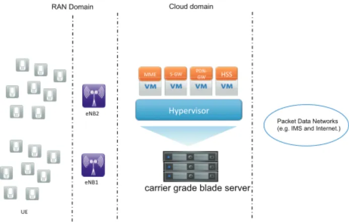
One important vision of the 5G mobile network architecture is to enable the on-demand creation of mobile networks on virtualization platforms and their management and offering as a cloud service, benefitting from all the nice features cloud computing offers; i.e., service elasticity, on-demand, and pay-per-use, to name a few. Such carrier cloud vision represents an efficient solution for mobile operators to cope with the ever-growing mobile data traffic while maintaining their CAPEX (Capital Expenditure) and OPEX (Operational Expenditure) costs within affordable ranges [1][2]. In the context of the Evolved Packet System (EPS) [3][4], carrier cloud may be formed out of a joint or separate virtualization of the Evolved Packet Core (EPC) and the Radio Access Network (RAN) [2]. Network function virtualization (NFV) is enabled by decoupling the software components of mo-bile core network/RAN nodes from their respective dedicated hardware, using virtual hardware abstraction techniques [5]. Mobile network functions accordingly become pieces of soft-ware runnable on any standard Virtual Machine (VM) on
any COTS (commercial off-the shelf) general-purpose multi-service multi-tenant node (e.g., a carrier grade blade server). Such virtual instantiation of mobile network functions (e.g., Mobility Management Entity - MME, Serving Gateway - S-GW, and Packed Data Network Gateway - PDN-GW), along with an adequate orchestration and management framework (e.g., OpenStack), enable flexible and on-demand creation of mobile networks, ultimately enabling the vision of EPC as a Service (EPCaaS) [6]. Appropriate Software Defined Networking (SDN) technologies can be used to interconnect different Virtualized Network Functions (VNFs) on different VMs in the same datacenter (DC) or across multiple DCs. VNF would give high degree of flexibility to mobile operators in the deployment of their mobile networks on the cloud. Thus, rapid deployment of mobile services (e.g., Machine Type Communications – MTC) can be guaranteed as network functions can be launched on demand and in a dynamic way on VMs [7]. Fig. 1 portrays a schematic illustration of the envisioned virtualized mobile core networks (i.e., EPCaaS), whereby important mobile network functions (e.g., MME, S-GW and PDN-S-GW) run as VNFs on top of VMs in a DC. The initial deployment of these VNFs onto the cloud infrastructure, their runtime management, and their inter-connectivity support are conducted by an adequate Service Orchestrator (SO) as detailed in [2][6]. Service resilience is an important require-ment in any communications system, especially in mobile networks, known for their five nines reliability. Furthermore, service availability and reliability, as specified by the ITU-T E.800, define a key parameter of the Quality of Service (QoS) characteristics. In the context of carrier cloud, ensuring service resilience becomes a challenge. Indeed, high availability is an important requirement of carrier grade, but not necessarily an intrinsic feature of cloud computing. Building a system that requires the five nines reliability on a platform that may not always grant it, is therefore a hurdle. Effectively, in carrier cloud, service resilience can be heavily impacted by a failure of any VNF running on a VM. The failure of a VNF may occur due to several factors, such as hardware failure (e.g., due to incorrect hardware dimensioning), software vulnerabilities and bugs in the running VNF (i.e., mainly if the VNF is composed of multiple VNF components, each deployed on its own
!"#$%&'()%* ++,* -./0* 123./0* !--* $345* $346* Cloud domain RAN Domain
Packet Data Networks (e.g. IMS and Internet.)
7,*
carrier grade blade server
Fig. 1. A high level architecture of cloud-based mobile core networks: Example of EPCaaS.
VM on the same or different hardware) or its corresponding VM, failure on the hypervisor level due to misconfiguration, negative performance impact due to other VNFs hosted on the same physical host, and malicious attacks against VNF or VM manager (i.e., hypervisor) [12]. In carrier cloud, VNF failure may impact the control plane (e.g., MME) as well as the user data plane (e.g., S-GWs or PDN-GWs). In the control plane, MME’s role is crucial since it is in charge of numerous important procedures (e.g., connection setup to a high number of user data plane nodes/VNFs, User Equipment - UE - mobility management, and UE authentication). Its failure significantly impacts the service provisioning, thus the importance of studying the service resilience of EPCaaS by defining prompt, scalable and reliable restoration mechanisms to recover from a failure of a MME VNF (as an example).
In this paper, our principal objective is not to solve the actual VNF failure issue, but rather to concentrate on the restoration mechanism and its impact on UEs. Furthermore, our focus is on the MME VNF failure restoration process, since MME VNF failure may concern a potential number of UEs and may result in service disruption, followed by a storm of signalling messages that may overload the network [8]. In current 3GPP specifications, solutions proposed to handle MME failure remain inefficient [9][10], as they work under the assumption that the system has to await the restart of the failed MME, and while waiting, any communications to/from UEs handled by the affected MME will be significantly affected. One possible alternative to ensure service resilience is by introducing redundancy. In the context of carrier cloud, this necessitates the instantiation of several instances of the target VNF (e.g., MME VNF) on several VMs. In general, redundancy would introduce undesirable additional cost to the operators. In case of carrier cloud, redundancy would further complicate the management of VNF instances and may result in scalability issues as more SDN rules may become required to efficiently steer mobile traffic. Last but not least, redundancy-based restoration solutions are not always desired by operators [9].
To overcome the above mentioned issues, we propose a proactive VNF failure restoration approach, focusing on the example of MME VNF failure. In the proposed solution,
as soon as a MME VNF goes off or starts malfunctioning, a new MME VNF instance is instantiated by the EPCaaS service orchestrator [2][6] (i.e., in case a normally functioning MME VNF with sufficient cloud resources is not available). MME relocation (to the new MME VNF instance) for affected UEs takes then place following the current specifications of 3GPP [3]. The key concept behind the proposed solution is to proactively trigger MME VNF relocation and restoration of lost state information (of affected UEs) to avoid service disruption at a later stage. It is worth stating that whilst an EPCaaS service orchestrator [2][6] can be heavily involved in a VNF failure recovery mechanism, it is desirable that it remains service agnostic: unaware of the underlying failure recovery mechanisms.
The proposed approach addresses UEs in both ECM (EPS Connection Management) idle mode and active mode. For the former, it triggers all affected idle-mode UEs through “scheduled/randomized” re-attach operations to the network [8]. As for the latter, it allows ongoing communications to proceed and triggers affected UEs to perform a Tracking Area
Update1 (TAU) operation in a scheduled manner according to
predefined priorities. Both mechanisms lead to the selection of another MME VNF (or the instantiation of a new MME VNF) for affected UEs and restoration of their context in a proactive manner. A number of mechanisms facilitating the selection of new MME VNFs for affected UEs and a proactive restoration of UEs’ context/state information are also envisioned. Furthermore, to handle the possible high number of signaling messages associated with the re-attach procedure, we propose two alternatives to reduce the load: (i) bulk signalling, i.e. create only one single message to replace a certain number of signalling messages in a bulk; (ii) create message profile, i.e. reduce the signaling message header by replacing repetitive information elements in messages by a profile identifier (ID), similar in spirit to [11].
The remainder of this paper is organized as follows. Section II discusses some background of this paper and presents some related research work. Section III introduces our proposed MME VNF restoration solutions with details pertaining to bulk signaling and profile creation, and that is for UEs in both ECM-idle mode and ECM-connected mode. Section IV introduces our envisioned Markov model for the analytical modelling and performance evaluation of the proposed solu-tions. The obtained results are discussed in Section V. The paper concludes in Section VI.
II. BACKGROUND AND STATE OF THE ART
Thanks to the numerous advantages it offers in terms of network configuration flexibility, scalability, and elasticity, VNF has emerged as an important topic of inquiry among different stakeholders in the telecommunications arena. Sev-eral pioneering research work have been conducted to enable the creation and runtime management of mobile networks over the cloud, studying different implementation options [6] and devising an entire framework for the creation of end-to-end 1A TAU operation is usually used by UEs to notify the network about their current locations within the network [13][14].
!"#$% &'()%* +,-* !"#$%&'()%* +,-* +,-* !"#$% &'()%* +,-* !"#$%&'()%* +,-* +,-* (a) (b) (c)
Fig. 2. Some deployment options of VNFs.
mobile services, including mobile transport networks, on the cloud [2]. Software Defined Networking (SDN) has been also considered in virtualization of mobile network functions over Open-Flow-based networks [27][28]. Other research work also considered the usage of SDN to virtualize the control plane of a mobile network on the cloud [29]. The concept of NFV is also explored in [30][31], focusing on the virtualization of the control plane; separately or jointly with the user data plane.
In such cloud-native 5G mobile networks, service continuity support becomes an important challenge as the software of EPC node functionalities is decoupled from its underlying hardware [2][6]. The likelihood of node failure, alternatively NF failure, becomes therefore significantly high. Effectively, depending on the deployment method of VNF (i.e., imple-mentation options in [6]), the sources of VNF failure may vary. The simplest way is to run the existing software of VNF as an image on a dedicated VM and execute it on virtual resources provided by the underlying hypervisor. In this case, the software added to the system introduces new failure sources, e.g. failure at the hypervisor level. Other deployment scenarios of VNF could consist in slicing the underlying hardware into a set of resources shared by sev-eral VNFs, as depicted in Fig. 2b. This introduces another failure source to the system. For instance, a particular VNF could impact the performance of another VNF sharing the same hypervisor if the resource isolation is not appropriately conducted. In a further scenario, components of a single VNF could be instantiated over multiple VMs running on separate hypervisors, as shown in Fig. 2c. In this case, a single/multiple failures of one/multiple components could occur, due in turn to failure of the underlying hardware or due to faults along the communication paths connecting the components/hypervisors. All in all, regardless the deployment mode of VNFs, i) a fast and accurate detection mechanism of VNF failures and ii) an almighty restoration mechanism from VNF failures are of vital importance [9][10].
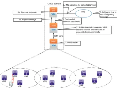
Considering the VNF of one of the most important nodes in EPC, namely MME, which is the focus of this paper, we showcase, in Fig. 3, a typical MME failure scenario, within the procedures currently defined in 3GPP standards [3][4], focusing on a terminating IMS (IP Multimedia Subsystem) call arriving after a MME failure. The following steps take place:
1) The MME (VNF) has failed (i.e., due to software or hardware reasons) and restarted (i.e., instantiating an image of the MME VNF at the same server after its recovery from hardware failure, or by instantiating an image of the MME VNF on a VM at another server).
!"#$ %&' ($%&' ))*' +#,' +#,' +#,' +#,' +#,' +#,' +#,' +#,' +#,' +#,' +#,' +#,' -*' IMS Cloud domain GTP echo 1. MME restart
2. S-GW detects incremented MME restarts counter and removes all associated resource locally 5. IMS signaling for call establishment
6. IMS error due to loss of signaling message 4. First packet
arrived is discarded 5a. Reject message
5b. Remove resource
Fig. 3. A typical MME failure scenario (within 3GPP specifications).
2) S-GW (i.e., be it a VNF or a conventional S-GW) detects the MME restart via the incremented MME restart counter in a GTP GPRS Tunnel Protocol -(echo message) and removes all User Equipment (UE) resources handled previously on this MME VNF. It should be noted that the removal of resources is not propagated directly up to the PDN-GW (Packet Data Network Gateway - be it a VNF or a conventional PDN-GW), i.e., the allocated IP address and a S5/S8 tunnel configuration in PDN-GW remains valid [3].
3) IMS signaling for call establishment arrives at the PDN-GW.
4) Data packets stemming from IMS arrive at S-GW and are discarded, due to unknown TEIDs (Tunnel Endpoint Identifiers).
5) (a) S-GW sends a reject message to the PDN GW; (b) upon reception, the PDN GW removes all resources linked to the relevant IP address.
6) The loss of the SIP (Session Initiation Protocol) signal-ing messages leads to an error situation in IMS, impact-ing the service and ultimately the system resilience. Intuitively, a major concern with the above-described solu-tion consists of the fact that the described approach is reactive. Indeed, it waits the restart of the failed MME VNF, and while waiting, any communications to/from UEs handled by the affected MME VNF will be significantly affected.
Given its criticality on service provisioning, recovery from the failure of network entities, within a mobile system, has been exhaustively investigated in the recent literature with several solutions being proposed. A framework that describes the initial efforts towards fault tolerance in wireless access networks is included in [15] focusing on GSM, where the primary means of fault provision is the introduction of trans-port and coverage redundancy and sever duplication. Fault tolerance in the arena of cloud computing, particularly for virtual machine placement, has been also heavily investigated as a mean to ensure resilience. In [31], a redundant VM placement scheme is proposed. The main constraint considered
in the placement decision is the incurred cost as the scheme aims at minimizing the total resources allocated to ensure a predetermined protection level. In [32], a protection-level based scheme is also proposed whereby the protection level changes in an agile manner as per changes in the QoS requirements of the target services. Overall, resilience and security in cloud has been heavily investigated through many research projects such as SECCRIT [33].
In mobile IP networks, restoration and recovery from failure can be achieved by duplicating mobility information at differ-ent agdiffer-ents. Thus, when one fails, the other operates instead as a backup. An embodiment of such policy is described in [16], whereby the primary and secondary mobility agents are organized in a dynamic manner while taking into account load balancing. Another variant focusing on mobile IP is introduced in [17], where double bindings ensure that a faulty mobility agent is promptly replaced by the backup one without the need for collecting any mobility information. This study further analyzes a fault tolerant protocol to manage the double binding and a load balancing method to distribute the load among the fault free mobility agents. A similar approach centered on UMTS is described in [18], where a per-user check point-ing approach is introduced for the Home Location Register (HLR). The proposed method regulates the duplication of HLR information considering user activity to reduce the associated overhead. Charging service failure mechanisms within UMTS, introduced in [19], focus on the GTP protocol, which is used to transfer charging data records. The provided analysis assists operators to reduce the probability of false failure detections and to shorten the detection latency.
Given the high dynamicity of mobile users along with the increase in the number and types of mobile applications, main-taining a double mobility registration is not only an expensive process, but also an inefficient one requiring significant syn-chronization effort. For this reason, alternative methods are proposed to dynamically select backup mobility agents on demand as introduced in [20]. In particular, once a mobility agent fails, the system estimates the affected load and selects the backup mobility agents performing load balancing and initiates a system driven proactive handover on the affected users. A similar distributed approach considering the recovery of lost data is presented in [21]. 3GPP LTE adopts the same failure detection and restoration approach regarding PCRF (Policy Charging and Rules Function) [10][22]. In the PCRF case, the failure can be detected by the DIAMETER protocol [23] or at the PCRF application level. During a PCRF failure, other PCRF entities are simply utilized instead with not much impact on the data plane.
In 3GPP LTE networks the adoption of the S1-flex provides the fundamental means for network redundancy among various network elements in the EPC creating pools of MMEs or S-GWs [13]. Such a pool may serve certain eNBs allowing them to be connected to multiple MMEs and SGWs at the same time. In this way when a particular MME or S-GW fails the affected UEs within the associated eNB may select another entity from the same pool. To the best knowledge of the authors, no prior research work addressed failure detection and restoration of EPS’s control and data plane nodes. Since
!"#$ (a) !"#%&$ (b) !"#%&$ !"#%&$ &'$ ()*+,-.$ /'$
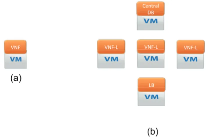
Fig. 4. Two implementation options of VNF on VMs: (a) a single VNF on a single VM, (b) a single VNF on a pool of VMs.
the control plane is of utmost importance, this paper aims to devise fault detection and restoration methods for the control plane avoiding double mobility registration. In addition, it introduces bulk signaling, which advances the current methods reducing the singling overhead within the core network as well as processing effort in the corresponding MMEs and HSS (Home Subscriber Server). Our vision is to provide such failure restoration service as a Self-Organized Network (SON) function [24][25], whereby network nodes may autonomously handle and adapt to the MME pool accordingly, while the reconfiguration process of affected MMEs is seamless.
III. VNF FAILURE RECOVERY: MME VNF CASE Recovery from a VNF failure depends largely on how the VNF is implemented. A number of implementation options can be envisioned [6]. Fig. 4 illustrates two exemplary ones. In Fig. 4a, a single VNF is instantiated on a single VM in a 1:1 mapping fashion. In Fig. 4b, components of a single VNF are instantiated on a pool of VMs in a 1:N mapping fashion. One VM runs a load balancer that balances the processing of incoming requests across multiple VMs running the logic of the underlying VNF (i.e., VNF-L). A central database can be instantiated on a separate VM hosting all state information about UEs connected to the VNF. In case of the 1:1 implementation option, a failure of the VNF (i.e., at the hardware level of the physical hardware providing VM or at the software level of VNF) would require a prompt recovery by instantiating a similar VNF on a different VM, restoring lost state information from other network nodes as explained below, and relocating all or subset of impacted UEs to the newly instantiated VNF (or to another appropriate existing one). In case of the 1:N implementation option, a failure of any VM running the VNF logic can be alleviated by balancing incoming requests to the appropriately working VNF-L VMs, till a new VNF-L VM is instantiated. A failure at the VM running the load balancing function can be also easily restored by promptly instantiating a new VM to do load balancing among the VNF-L VMs. However, a failure at the central database VM may lead to loss of important state information that cannot be easily retrieved. It may also
!"#$ !"#$ !"#$ !"#$ !"#$ !"#$ !"#$ !"#$ !"#$ !"#$ !"#$ !"#$ %&$ ''&$ ''&$ ''&$
Failed MME (VNF 1) Other MMEs
2. Failure detection on S1-MME 3. Bulk or profile paging
to all all Ues assigned to the failed MME VNF
2. Re-attachement of affected Ues another MME within the same pool 1. MME failed
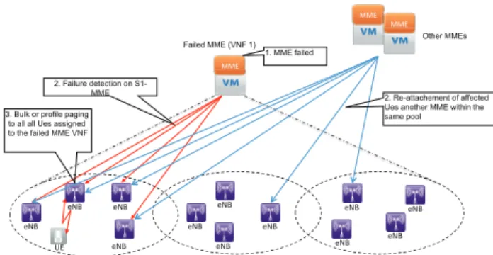
Fig. 5. eNB-initiated paging for MME VNF failure restoration.
hinder the working of VNF-L VMs, resulting in a total failure of the entire VNF. A subset of lost state information can be restored from other network nodes serving the impacted UEs, as explained below. In the remainder of this paper, we consider the worst case scenario whereby the whole VNF fails as in the 1:1 implementation option (i.e., alternatively, when the CDB VM fails in case of the 1:N implementation option).
The proposed VNF failure recovery framework is a combi-nation of different mechanisms, each with a specific objective, yet all aiming for a proactive and prompt VNF failure restora-tion to ensure Carrier Cloud service resilience. Firstly, there are different ways for the detection of a VNF failure. The first method could be via an explicit intervention/notification from the monitoring entity of the underlying datacenter (e.g., Ceilometer of OpenStack). Indeed, any abnormal behavior of the VM running the VNF can be noticed by the monitoring entity and reported directly to the Carrier Cloud service orchestrator [2][6]. Failure detection can be done also by the Operations & Maintenance (O&M) system of the EPC to which the VNF in question belongs. Indeed, O&M could detect VNF failure i) based on feedback from supervising software daemons running on the same VNFs or hosted on another VM, ii) based on periodic keep-alive/echo messages and responses, iii) having VNF immediately send an alarm to O&M right before it crashes (i.e., possible in case of partial failure or VM bugs), or iv) by analyzing related information (e.g., handover occurrences in case of MME VNF failure) from other VNFs/network nodes. In case of MME VFN failure, which defines the focus of this paper, it can be also detected directly by eNBs using S1-MME (i.e., using keep-alive messages of the Stream Control Transmission Protocol - SCTP - [34]). Alternatively, MME VNF failure can be detected by neighboring MME VNFs (i.e., VNFs deployed on other datacenters to cover other Serving Areas) using S10 protocol means or by S-GW VNFs using S11 protocol means. In the remainder of this section, we discuss how MME VNF restoration can be separately achieved for UEs in ECM-idle mode and for those in ECM-active mode.
A. MME VNF restoration for idle mode UEs
1) Principle: The proposed procedure, shown in Fig. 5, is
based on an enhancement to the paging procedure that enables paging of all UEs that have been served by a particular MME
[35]. Indeed, the “bulk” paging is characterized by the use of MME information - which is the leading part of GUTI - Globally Unique Temporary Identity - as identifier [3]. As shown in Fig. 5, upon detecting failure of MME VNF 1, all eNBs, with S1-MME connection to MME VNF 1, initiate a bulk paging of all UEs being served by the failed MME VNF 1, with identity of the failed MME VNF and some indica-tors for overload avoidance (e.g., randomized time interval) as will be explained later. During the re-attachment, eNBs redistribute responding UEs on the MME VNFs remaining in operation, taking load balancing into account. The service request procedure, initiated by a UE, as response to the paging will lead indirectly to a re-attach, in the following sequence. Effectively, a UE sends a SERVICE REQUEST message to the eNB. Due to the failure of the originally assigned MME VNF, the eNB needs to redistribute the UE to another MME VNF by releasing the Radio Resource Control (RRC) connection, e.g., using the cause - Load Balancing TAU Required - [3]. The UE will re-establish the RRC connection and subsequently perform a TAU. Such a mechanism would in principle trigger many UEs to re-attach at the same time. To avoid overload at the newly selected MME VNFs, the re-attach attempts should be spread out over time. This can be achieved by different mechanisms as will be explained later. Alternatively to the above-mentioned Service Request-based procedure, a UE may also re-attach to the network after receiving a paging message as a result of a MME VNF failure (i.e., indicated via a flag in the paging message) and that is following the usual attach procedure [3]. Paging UEs in idle mode and affected by the MME VNF failure can be also initiated by neighbouring MME VNFs. Generally speaking, a MME VNF A is said to be a neighbor of MME VNF B if both MMEs have at least one common Tracking Area [13] in their managed Service Area. Effectively, one or more neighboring MME VNFs may detect the failure of a MME VNF. They will then initiate bulk paging addressing idle mode UEs, with identity of the failed MME VNF and some indicators for overload avoidance, to trigger corresponding UEs to re-attach to the network (e.g., indicating “load balancing TAU required” as in [3]).
In this solution, duplicate paging shall be minimized, if not entirely avoided. This can be achieved via different methods. In case a neighbor MME VNF detects the MME VNF failure, it immediately starts the paging and notifies its neighboring MME VNFs that it has already paged the concerned UEs and there is no need to do that from their side. This mechanism assumes that MME VNFs have prior knowledge on the pool of MME VNFs that are able to cover a failed MME VNF. In case O&M detects the MME failure and notifies the neighboring MME VNFs, O&M explicitly indicates to each MME VNF which Tracking Area it should page. Additionally, eNBs may filter out duplicated paging messages stemming from different MME VNFs. In case of an inevitable reception of duplicate paging messages, a UE simply considers the first paging message and discards the following ones. For the sake of load balancing, the concerned eNBs run a MME VNF load balancing scheme (excluding the failed MME VNF) to ensure that not all UEs would connect to the same MME VNF as in [3]. Such load balancing at eNBs can be omitted in case
MMEs UEs
eNB
!!"# !!"# !!"# !!"# $%%#
Failed MME HSS
MME Failure Detection
Bulk Paging
Aggregation TAU Request Messages
Aggregation TAU Request/Response Messages
Fig. 6. Idle mode signaling for redistributing UEs to operative MME VNFs after a MME VNF failure and possible places for signaling message aggregation.
the MME VNF, selected to cope with the affected UEs, is implemented in a 1:N fashion, as described above.
2) Bulk signaling management: Whilst signalling
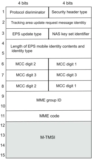
conges-tion, due to simultaneous attempts from many affected UEs, can be avoided at MME VNFs by taking load balancing into account, this imminent congestion can be also avoided by handling signalling messages from affected UEs in bulk. Indeed, to cope with the constraints MME VNFs may have in terms of the maximum number of signaling messages (e.g., Tracking Area Updates in Fig. 6) they can handle per second, eNBs could hold back signaling messages (e.g., TAUs) from UEs in order to aggregate them and send them in one single message towards MMEs. MMEs could do also the same operation for several location updates (i.e., being part of the TAU procedure) towards HSS (Fig. 6). For example, MMEs may wait for a predefined timeout or till a number of location update requests arrive (or both) to proceed with a bulk of location update requests towards HSS. Using the possible aggregation of TAU messages, being issued from a large number of UEs, at eNBs as shown in Fig. 6, we demonstrate the potential of bulk MTC signaling in comparison to the state of the art. TAU messages consist of mandatory fields, worth 15 octets and a set of optional fields (see Fig. 7). Since we concentrate only on UEs that are associated with the same MME VNF, the only parameter which is UE specific, is the M-TMSI (MME Temporary Mobile Subscriber Identity), which identifies a device at one MME VNF. The other fields, consisting 11 octets out of a total of 15 octets, are common to all UEs associated with the MME VNF. Assuming N affected UEs associated with the same MME VNF, it is possible to bulk N TAUs in a single message of (4 N + 11) Bytes, while with individual messages (N x 15) Bytes are needed. As shown in Fig. 6, further aggregation towards HSS could be made at the MME VNF; this means that the message content can be compacted considerably. Moreover, the effort of parsing the parameters of many messages is also reduced to a minimum, which shall reduce by a large factor the overall time spent for the procedure. Accordingly, signaling efficiency can be improved even if all Information Elements (IEs) for the many
4 bits 4 bits
Tracking area update request message identitiy
Length of EPS mobile identity contents and identity type
MCC digit 2
Protocol disriminator Security header type
NAS key set identifier EPS update type
MCC digit 1 MCC digit 3 MCC digit 3 MCC digit 2 MCC digit 1 MME group ID MME code M-TMSI 1 2 3 4 5 6 7 8 9 10 11 12 13 14 15
Fig. 7. A typical format of a TAU message.
original signaling messages would differ, just by avoiding the processing of multiple messages (e.g., every message must be acknowledged, i.e., protocol state needs to be kept for some time) and by much more efficient parsing. It is also of vital importance that eNBs are not congested with too many signalling messages from affected UEs. This can be achieved by scheduled paging and/or their responses. Indeed, bulk paging at MME VNFs or eNBs can be performed per specific groups of UEs, based on certain priority metrics (e.g., access class), or in a randomized manner using a predefined randomization time. Responses from UEs can be also carried out in a randomized manner and over a time interval follow-ing a hash function that takes UEs’ unique identifiers (e.g., International Mobile Subscriber Identity - IMSI, subscription information available at UE, etc.) as input values (based on new UE functionality).
3) Profile ID-based signaling management: Although
han-dling signaling messages (e.g., TAU messages) in bulk have advantages, its main drawback is the delay it adds in pro-cessing the messages. Indeed, the sending node (i.e., eNB) has to await a timeout or till a number of signaling messages is received, before processing with the delivery of signaling messages to the recipient (e.g., MME VNF). The purpose of
4 bits 4 bits
Tracking area update request message identitiy
Length of EPS mobile identity contents and identity type
MCC digit 2
Protocol disriminator Security header type
NAS key set identifier EPS update type
MCC digit 1 MCC digit 3 MCC digit 3 MCC digit 2 MCC digit 1 MME group ID MME code M-TMSI 1 2 3 4 5 6 7 8 9 10 11 12 13 14 15 2 3 4 5 1 Profile ID M-TMSI 8bits TAU with profile ID
Fig. 8. Example of profile ID creation: TAU message.
the solution proposed herein is to achieve the goal of the “bulk” in reducing the amount of traffic sent on the network, but without compromising the delay in handling messages. The proposed solution defines methods for creating and managing, in a dynamic way, profile identifiers referring to a set of IEs that are common in messages relevant to a group of UEs and replacing the common IEs with the created profile ID. Creating a profile ID to refer to these common IEs and sending it instead of all common IEs would definitely reduce the amount of traffic exchanged between the eNB and the MME VNF. The importance of replacing common IEs in messages by a profile ID, similar in spirit to Robust Header Compression (ROCH), becomes more significant knowing that the size of messages is increasing with every release of the specifications. Fig. 8 depicts the case of creating profile ID for a TAU message. As mentioned in the bulk signaling management solution, a TAU message consists of mandatory fields, worth 15 bytes, and a set of optimal fields. Considering only UEs that are associated with the same MME VNF, the only parameter that is UE-specific is the M-TMSI. Therefore the other IEs are common and can be grouped and replaced by a profile ID, as shown in Fig. 8. Referring to Fig. 6, the nodes that could be potentially involved in the creation of the profile ID are eNBs and the MME VNFs selected for restoration. The profile ID can be a random value or a function of the group ID of relevant UEs and other metrics. The group ID can be explicitly indicated in the messages, inferred from the eNB (and/or other information elements) of relevant UEs, inferred from subscription data of UEs downloaded on demand or a priori from HSS or another relevant node, or inferred from a mapping between the relevant procedure and the locations (e.g., cells, tracking areas, service areas, etc.) of the relevant UEs. As second step, eNBs communicate the profile ID and its features to the MME VNF, optionally along with instructions on when to delete the profile ID at the receiver, event type, etc. This notification can be either in the form of a dedicated signaling message or can be inserted into the first relevant message sent after the profile creation. The profile notification message can be optionally acknowledged by the MME VNF.
New MM U eNB !!"# $%&'# ($$# Detect MM fail , 1. S1-AP-S1: U Re
2. Update Acce Bearer Re 3. Update Acce Bearer Re Detect MM Fail 4. S1-AP: S1 U Re 5. Tracking Area A Update Location Re Update Location Re Tracking Area
Fig. 9. Example of profile ID creation: TAU message.
In response, the MME VNF stores the profile ID and its attributes. For the subsequent messages relevant to the profile ID, the eNBs do not insert common IEs; they instead insert only the profile ID. In this way, the amount of communications on the interface between the two entities (eNBs and MME VNFs) can be reduced; a reduction that becomes important in case of a potential number of UEs being affected by the failed MME VNF. Using again the example of TAU messages, the profile ID will generate (Nx6) Bytes (when N UEs are affected), which is less than the classical procedure (Nx15) Bytes, but more than the case of Bulk (4N+11). However, the profile ID based signaling management solution reduces significantly the delay in processing signaling messages. B. Restoration from MME VNF failure for affected UEs in active mode
Regarding UEs in ECM-connected mode and which are affected by a MME VNF failure, the objective is to get their contextual/state information, previously available at the failed MME VNF, which is distributed over different network entities (e.g., S-GW VNF, P-GW VNF, and eNB) without impacting the ongoing sessions of the UEs. Recovering pieces of state information from different network entities could be an inter-esting approach, particularly in case of the failure of the VM running the central database of a NFV implemented in a 1:N fashion. The state of the art solution is to duplicate/mirror all information in highly resilient nodes/database implementations of VNFs. Accordingly, whenever a MME VNF fails, the UE contextual information can be recovered instantaneously from these mirrors. However, this intuitively comes at high costs in terms of configuration. In contrast, the solution, described in the remainder of this section, is based on more intelligent, cooperative behavior among network elements or functions, which allows a considerably simpler MME VNF implementation, corresponding to the Carrier Cloud vision [2][6]. In particular, a newly selected MME VNF (after failure of the serving MME VNF) will recover the state information from eNBs (step 1 in Fig. 9) and S-GW VNFs (step 3 in
Fig. 9). The state information recovered by the new MME VNF from the S-GW VNFs (in step 3) include per UE bearer information such as IMSI, Mobile Equipment Identity, S-GW TEID (Tunnel Endpoint Identifier) for S11/S4 interfaces, PDN-GW IP address and TEID for S5/S8 interfaces, eNB TEID for S1-u interface, PDN charging characteristics, and EPS bearer QoS. The state information recoverable by the new MME VNF from eNBs (in step 1 in Fig. 9) include per UE, EPS bearers information (TEID and eNB IP address) and Aggregate Maximum Bit Rate (AMBR). Since per UE and EPS bearer information must be exchanged for many UEs, the information exchange between eNB / SGW and MME VNF (steps 1-4) can also be achieved by means of bulk signaling or profile-ID creation (i.e., per UE and EPS bearer information can be aggregated in a single signaling exchange). The flowchart of the proposed solution is shown in Fig. 9. The mechanism is applied by each eNB being in a tracking area that was serviced by the failed MME VNF. It concerns only UEs in connected mode that have been registering with the failed MME VNF. Note that an eNB can easily sort out these UEs. The steps of this solution are as follows:
1) eNB detects MME VNF failure and selects a new one out of the remaining MME VNFs in operation. In case another MME VNF is not available, the EPCaaS service orchestrator may be triggered to instantiate a new MME VNF [2][6]. Load balancing is taken into account in the selection of a new MME VNF, particularly when VNFs are implemented in a 1:1 mapping fashion [6]. MME VNF selection can be done for an individual active UE or for a set of active UEs with common factors (e.g., being assigned the same S-GW VNF, those to experience imminent handoffs, etc) and defined by a unique identifier (e.g., Connection Set ID according to [9]) allocated locally. Prioritization among the UEs or the formed sets of UEs can be envisioned, i.e., intuitively UEs with imminent handoffs should be prioritized over other UEs
2) eNB sends UE’s S1 bearer information to the selected MME VNF requesting a UE context update. Some of the provided context could be UE’s IMSI, corresponding S-GW VNF, and reason for update (i.e., failure of the relevant MME VNF). A bulk of update requests can be also performed for each formed set of UEs.
3) MME VNF then sends an Update Access Bearer re-quest to the corresponding S-GW VNF querying UE’s S1 bearer information. MME VNF, in turn, can also group UEs into different groups, uniquely and locally identified, and send a bulk of update bearer requests for each formed group of UEs.
4) In response, S-GW VNF sends an Update Access Bearer Response. Here, the information on the corresponding PDN-GW VNF can be also included.
5) As a confirmation, the newly selected MME VNF re-sponds with a S1 UE context update response to the eNB
6) When UE detects MME VNF failure (e.g., based on error message following an attempt to initiate a new
0,1 1,1 2,1 n,1 0,0 1,0 2,0 n,0 ! f f f f r r r r nλ µ (n-1)λ (n-2)λ λ nµ 3µ 2µ
Fig. 10. Transitions graph of the envisioned system.
PDN connection using old GUTI) or is triggered to perform TAU (e.g., by eNB via a RRC connect signaling message), it sends a tracking area update. MME VNF relocation will then take place without impacting the user plane, ensuring service continuity.
It should be noted that while in the above-described flow, the TAU request is handled for each individual UE in connected mode, the same bulk signaling handling, described for UEs in idle mode, could be applied.
IV. ANALYTICALMODEL
A. System Models
Having described in details the proposed VNF failure restoration solutions in carrier cloud, we focus our attention, in this section, on providing an analytical model of the overall framework. The key objective of the envisioned model is to estimate the number of active/idle UEs when a MME VNF fails. Here, we consider an EPCaaS system consisting of one
MME VNF, one eNB and n UEs. We assume that each UE
is either in Idle or Active mode. We assume that the time duration of a UE in Idle mode (resp. Active mode) follows
an exponential distribution with rateµ (resp. λ). In the same
way, the time duration before a MME VNF failure occurs and the time duration for restoring from a failed MME VNF are
exponentially distributed with respective ratesf and r. These
assumptions lead us to model the system using a Markov
chain X = {Xt, t ≥ 0} on the state space S defined by
S = {(i, j) | i = 0, . . . , n and j = 0, 1}, for every n ≥ 1
In this model, Xt = (i, j) indicates that, at time t, there
are i active UEs in the network and the MME VNF is in
state j. While j = 0 indicates that the MME VNF is in the
failed state,j = 1 represents the fact that the MME VNF is
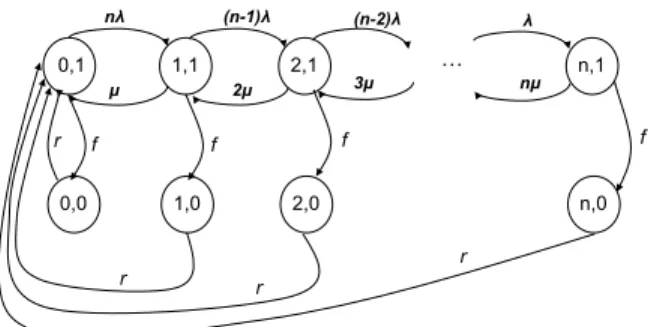
working properly. Fig. 10 illustrates the transitions graph of the envisioned system.
The different transitions are as follows:
• If a UE goes to active mode while already i (0 ≤ i ≤
n − 1) UEs are active and the MME VNF is active, then
there is a transition from state (i, 1) to state (i + 1, 1)
with rate(n − i)λ.
• If a UE goes to idle mode while already i (1 ≤ i ≤ n)
UEs are active and the MME VNF is active, then there
is a transition from state(i, 1) to state (i − 1, 1) with rate
• If a MME VNF failure occurs while alreadyi (0 ≤ i ≤ 0)
are active and the MME VNF is active, then there is a
transition from state(i, 1) to state (i, 0) with f .
• If the MME VNF is recovered while already i (0 ≤
i ≤ n) are active, then the system transits from state (i, 0) to state (0.0) with rate r. We argue this transition by the fact that recovering from a MME VNF failure leads to its restart or the instantiation of a similar MME VNF on a new VM. However, no UEs are attached to the restarted/instantiated MME VNF until eNBs become aware of this new state. In the proposed model, we assume that eNBs become instantly aware of any change in the MME VNF state via the incremented MME restart counter sent through the GTP tunnel.
We denote by A the infinitesimal generator of X. The
off-diagonal entries of matrixA are thus
A(i,0),(i+1,0)= (n − i)λ, for i = 0, . . . , n − 1,
A(i,0),(i−1,0)= iµ, for i = 1, . . . , n,
A(i,0),(i,1)= f, for i = 0, . . . , n,
A(i,1),(0,0) = r, for i = 0, . . . , n.
The diagonal entries of A are, for i = 0, . . . , n, A(i,1),(i,1)=
−((n − i)λ + iµ + r) and A(i,0),(i,0)= −r.
The Markov chain X being irreducible and with finite
state space, it has a limiting distribution that we denote by
π. We thus have for every (i, j) ∈ S, limt−→∞ {Xt =
(i, j)} = π(i,j). To compute the stationary distribution π,
we introduce the set S0 = {(i, 0) | i = 0, . . . , n} and
S1= {(i, 1) | i = 0, . . . , n}. This partition of the state space
S induces a decomposition of matrix A as A = ! Q D1 C D2 " ,
where matrixQ contains the transition rates between states of
S1, matrixD1contains the transition rates from states ofS1to
states ofS0, matrixC contains the transition rates from states
of S0 to states of S1 and matrix D2 contains the transition
rates between states of S0. Note that we have D1 = f I and
D2= −rI, where I is the (n + 1, n + 1) identity matrix. The
stationary distributionπ satisfies
πA = 0 and #
(i,j)∈S
π(i,j) = 1.
We decompose the row vectorπ using the partition S1, S0 as
follows:
π = (π(1), π(0)).
The linear system πA = 0 can then be written as
$
π(1)Q + π(0)C = 0
π(1)D
1+ π(0)D2 = 0.
We then have π(0) = f π(1)/r. We denote by the column
vector with all entries equal to1; its dimension being specified
by the context of its use. We obtain
1 = π = π(1) + π(0) =f + r r π (1) . We thus obtain π(1)(Q + f C/r) = 0 with π(1) = r f + r.
The matrix T = Q + f C/r is the transition rate matrix of an
irreducible Markov chain on the state spaceS1. Its stationary
solutiony satisfies yT = 0 with y = 1. We thus have
π(1) = r
f + ry and π
(0)= f
f + ry.
In order to computey, we consider the linear system yT =
0, which can be written as: ⎧ ⎪ ⎪ ⎨ ⎪ ⎪ ⎩ −nλy0+ (µ + f )y1+ f (y2+ · · · + yn) = 0
(n − i + 1)λyi−1− ((n − i)λ + iµ + f )yi
+ (i + 1)µyi+1= 0, for i = 1, . . . , n − 1
λyn−1− (nµ + f )yn = 0 or equivalently as ⎧ ⎪ ⎪ ⎨ ⎪ ⎪ ⎩ −(nλ + f )y0+ µy1+ f = 0
(n − i + 2)λyi−2− ((n − i + 1)λ + (i − 1)µ + f )yi−1
+ iµyi= 0, for i = 2, . . . , n
y0+ y1+ · · · + yn= 1,
(1) where the last equation of the previous system has been
replaced by the normalizing conditiony = 1. We then have
the following recurrence relation ⎧ ⎪ ⎪ ⎪ ⎨ ⎪ ⎪ ⎪ ⎩ y1=nλ + fµ y0−fµ yi= (n − i + 1)λ + (i − 1)µ + fiµ yi−1
−(n − i + 2)λiµ yi−2, for i = 2, . . . , n.
To solve this recurrence, we start with any positive value ofy0,
sayy0= 1, then we compute all the yi, fori = 1, . . . , n and
finally we get the real values ofyi by dividing each computed
value by the sum of theyi. Oncey is obtained we easily get
vectorsπ(1) andπ(0) and therefore vectorπ.
We denote by NI (resp. NA) the number of UEs in idle
(resp. active) mode when the MME VNF is recovered. We
then haveNA + NI = n
{NA = ℓ} = πℓ,0 and {NI = ℓ} = πn−ℓ,0
and so the expectations are E[NA] =
n
#
ℓ=1
ℓπℓ,0andE[NI] = n − E[NA].
B. Performance metrics
Knowing the average number of active/idle UEs, we can evaluate the performance of the two proposed signaling management solutions, bulk signaling and profile ID-based signaling management. As comparison terms, we use two other conventional solutions. In one solution, all UEs are notified at the same time; whereas in the other, UEs are notified using a random notifications scheme. Indeed, once a MME VNF failure occurs, the affected UEs perform TA updates based on the following four schemes: (i) TAU with no intelligence, whereby all UEs perform TA updates at the same time; (ii) TAU based on random notification, whereby UEs
are notified when to perform a TA update based on a random distribution; (iii) TAU based on bulk signaling, whereby UEs are notified similarly to the random notification-based TAU and additionally eNB performs bulk signaling; (iv) profile ID-based TAU, whereby TAU messages are compressed using a relevant profile ID and all UEs perform updates based on a random notification. Most of the metrics considered herein are for the MME restoration case whereby affected UEs are in idle mode. Recall that we use a uniform distribution with
a mean Tu/2 to allow UEs to randomly perform TA updates.
Tu is the time period used to disperse UE signaling to avoid
simultaneous transmissions.
1) Signaling overhead: Signaling overhead allows us to
compare among the above-described schemes in terms of the cost incurred by the exchanged signaling messages, after the failure of a MME VNF and during a predetermined time period T . For a TAU operation with no intelligence, the average size of the exchanged messages is given as follows:
E[msg] = 15E[NI]
Here, the size depends only on the number of TAU messages needed to relocate UEs from one MME VNF to another MME VNF or to reconnect UEs to the restarted MME VNF. Since all UEs are notified at the same time, all UEs in idle mode are concerned by sending a TAU message of 15 bytes. The random notification-based TAU approach is different, as UEs are explicitly informed when to perform TAU based on a random distribution. Thus, the average overhead due to signaling messages sent in this case is given by:
E[msg | NI = ℓ] = 15 ℓ # i=1 i!ℓ i " pi(1 − p)ℓ−i that is E[msg] = 15 n # ℓ=0 ℓ # i=1 i!ℓ i " pi(1 − p)ℓ−iπn−ℓ,0,
wherep is a probability that a UE sends a TAU message during
the time interval T. This probability is equal to T /Tu, where
T ≤ Tu.
For the bulk signaling-based TAU scheme, the average size of the signaling messages is given as follows:
E[msg | NI = ℓ] = 11 + 4 ⌈ℓ/k⌉ # i=1 i!⌈ℓ/k⌉ i " pi(1 − p)⌈ℓ/k⌉−i that is E[msg] = 11 + 4 n # ℓ=0 ⌈ℓ/k⌉ # i=1 i!⌈ℓ/k⌉ i " pi(1 − p)⌈ℓ/k⌉−iπ n−ℓ,0
where⌈ℓ/k⌉ is the size of the bulk. It represents the number
of TAU messages that a eNB must await to create a bulk. Finally, for the profile ID-based TAU scheme, the average signaling overhead is given by:
E[msg | NI = ℓ] = 11 ℓ # i=1 i!ℓ i " pi(1 − p)ℓ−i that is E[msg] = 11 n # ℓ=0 ℓ # i=1 i!ℓ i " pi(1 − p)ℓ−iπn−ℓ,0.
2) Dropping probability at the eNB: This metric represents
the dropping probability of TAU signaling messages sent by
UEs after a MME VNF failure. We denote by CeN B the
capacity of the eNB to handle TAU messages at the same time.
For the baseline TAU scheme with no additional intelligence,
the loss event is the event {NI > CeN B}. The dropping
probability at eNB is thus derived as follows:
Pdrop= {loss} = {NI > CeN B}
=)n
ℓ=CeN B+1πn−ℓ,0=
)n−CeN B−1
ℓ=0 πℓ,0.
For the random notification-based TAU scheme, this probabil-ity is given by
Pdrop =)nℓ=CeN B+1 {loss | NI = ℓ} {NI = ℓ}
=)n ℓ=CeN B+1 )ℓ i=CeN B+1 !ℓ i " pi(1 − p)ℓ−iπ n−ℓ,0
Finally, for the bulk signaling-based TAU scheme, it is given as follows:
Pdrop=)nℓ=CeN B+1 {loss | NI = ℓ} {NI = ℓ}
=)n ℓ=CeN B+1 )⌈ℓ/k⌉ i=CeN B+1 !⌈ℓ/k⌉ i " pi(1 − p)⌈ℓ/k⌉−iπ n−ℓ,0
It is worth noting that in case of using profile ID-based signaling management mechanism, the drop probability is equal to the case of random notification-based TAU scheme. This is attributable to the fact that the profile ID-based TAU approach compresses the TAU message size, but does not reduce the number of TAU messages in the network.
3) Overall processing time: This metric helps in showing
the impact of reducing the number of signaling messages (bulk signaling approach) or their size (profile ID-based approach) on the processing time of each message by the core network entities. For this purpose, we assume that there are M entities involved in a particular process (e.g., in case of
TAU procedure,M = 5, involving eNB, MME VNF, S-GW
VNF, PDN-GW VNF, and HSS), each with an average bit
processing speed P and an inter-process delayd.
In case of the baseline TAU scheme involving no additional intelligence, the processing time needed during a time interval T is given by: processing = M! 15NI P + dNI " if NI ≤ CeN B M! 15CeN B P + dCeN B " if NI > CeN B
The expected processing time is then given by E[processing | NI = ℓ] = M*15 P + d+ *ℓ1{ℓ≤CeN B}+ CeN B1{ℓ>CeN B} + that is E[processing] = M*15 P + d +,)CeN B ℓ=0 ℓπn−ℓ,0+ CeN B )n ℓ=CeN B+1πn−ℓ,0
-TABLE I
PARAMETERS USED IN THE NUMERICAL ANALYSIS AND THEIR VALUES.
nMME 1 neNB 1 nUE 200 M 5 d 0.02s Tu 0.2s CeNB 20 msg P 20 msg/s
For the random notification-based TAU scheme, the average processing time duration is derived as follows:
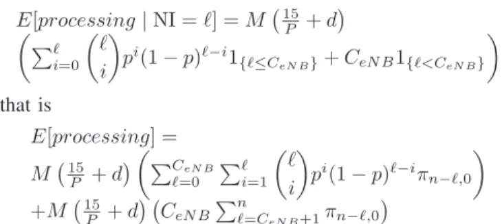
E[processing | NI = ℓ] = M*15 P + d + ! )ℓ i=0 !ℓ i " pi(1 − p)ℓ−i1 {ℓ≤CeN B}+ CeN B1{ℓ<CeN B} " that is E[processing] = M*15 P + d + ! )CeN B ℓ=0 )ℓ i=1 !ℓ i " pi(1 − p)ℓ−iπn−ℓ,0 " +M*15 P + d+ *CeN B )n ℓ=CeN B+1πn−ℓ,0 +
For the bulk signaling-based TAU scheme, the average pro-cessing time duration can be computed as follows:
E[processing | NI = ℓ] = M (4⌈ℓ/k⌉ + d) , that is
E[processing] = M (4)n
ℓ=0⌈ℓ/k⌉πn−ℓ,0+ d)
Finally, for the profile ID-based TAU approach, the average processing time duration is derived in the same way as follows:
E[processing] = M*11 P + d + )CeN B ℓ=0 )ℓ i=1 !ℓ i " pi(1 − p)ℓ−iπ n−ℓ,0 + M*15 P + d+ CeN B )n ℓ=CeN B+1πn−ℓ,0.
4) Bulk size: This metric concerns only the proposed bulk
signaling management solution. Indeed, this metric indicates the probability that a bulk is created during a certain time
periodT . It depends on the bulk size Bsize and T . It is given
as follows: {bulk creation} = )n ℓ=Bsize+1 )ℓ i=Bsize+1 !ℓ i " pi(1 − p)ℓ−iπ n−ℓ,0 wherep = T /Tu. V. NUMERICAL RESULTS A. Scenarios
This section evaluates and compares the performance of the above-mentioned four mechanisms using the above-described Markov chain-based analytical model. The envisioned network consists of one MME, one eNB, and 200 UEs connected to
the eNB. We defineρ = λµ as the ratio of the duration when a
UE is in idle mode to the duration when it is in active mode.
The higher the value ofρ is, the higher the likelihood of a UE
to be in active mode. We assume that the eNB cannot handle
0 50 100 150 200 250 300 350 400 0.01 0.1 1 10 E[msg] Active/Idle No Intelligence Random Notification Bulk Signaling Profile ID
(a) Medium failure rate scenario.
0 100 200 300 400 500 600 700 800 900 0.01 0.1 1 10 E[msg] Active/Idle No Intelligence Random Notification Bulk Signaling Profile ID
(b) High failure rate scenario. Fig. 11. Average signaling overhead.
more than 20 TAU requests at the same time; in case more TAU requests reach the eNB at the same time, the additional ones are simply dropped. Two scenarios of MME VNF failure are considered:
• High failure rate, wheref =1 week and r=3 days.
• Medium failure rate, wheref =3 weeks and r=3 days.
Table I summarizes the different values used to derive the numerical results.
B. Results
Fig. 11 plots the signaling overhead for the four schemes in both scenarios. Here, the bulk size is set to 50 messages, i.e., 50 messages are required to create a bulk. As expected, we observe that the bulk signaling-based approach achieves the best results, followed by the Profile ID-based mechanism. This performance is attributable to the fact that the bulk signaling based scheme reduces the number of signaling messages sent between the eNB and the MME VNF, while the Profile ID-based scheme reduces the signaling message size by creating a dedicated profile ID replacing the common IEs in TAU messages, compressing accordingly the signaling messages. Moreover, we notice that for all schemes apart of the bulk signaling-based scheme, the signaling overhead experienced in case of the high failure rate scenario is higher than that experienced in the medium failure rate scenario. Indeed, the bulk signaling-based scheme maintains very low overhead under both scenarios. From the figure, it is also observed that
the signaling overhead increases when there are more UEs in idle mode than UEs in active mode. Finally, the random notification-based signaling management mechanism exhibits better results than the baseline TAU approach. This suggests that with some minor intelligence incorporated in the signaling management, important gains can be achieved in terms of reducing the signaling overhead.
0 0.05 0.1 0.15 0.2 0.01 0.1 1 10 Pdrop Active/Idle No Intelligence Random Notification Bulk Signaling
(a) Medium failure rate scenario.
0 0.05 0.1 0.15 0.2 0.25 0.3 0.35 0.4 0.01 0.1 1 10 Pdrop Active/Idle No Intelligence Random Notification Bulk Signaling
(b) High failure rate scenario. Fig. 12. Signaling message dropping probability.
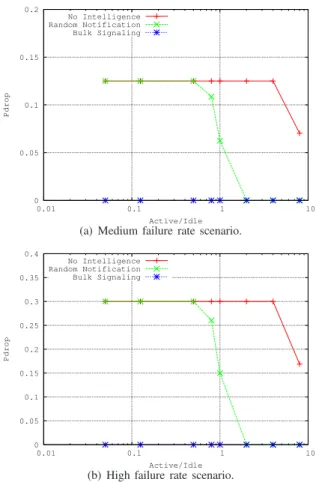
Fig. 12 shows the dropping probability of TAU messages under the two envisioned scenarios. The figure does not plot results of the Profile ID-based signaling management scheme as they are similar to those obtained by the random notification-based scheme. Again, the bulk signaling-based mechanism exhibits the best performance as it reduces the number of messages transmitted to the minimum, not exceed-ing the eNB capacity. The worst case is observed in case of the baseline TAU approach, wherein the drop probability remains at the maximum value (for both scenarios) until the proportion of active/idle UE (ρ) reaches 10. We argue this by the fact that when the baseline solution is used all idle UEs try to send TAU messages at the same time, which leads to exceed the eNB capacity most of time.
0 2 4 6 8 10 0.01 0.1 1 10 E[Processing] Active/Idle No Intelligence Random Notification Bulk Signaling Profile ID
(a) Medium failure rate scenario.
0 2 4 6 8 10 12 0.01 0.1 1 10 E[Processing] Active/Idle No Intelligence Random Notification Bulk Signaling Profile ID
(b) High failure rate scenario. Fig. 13. Average processing time.
A similar trend is seen in Fig. 13, which plots the average processing time obtained in case of the four signaling manage-ment schemes and under both scenarios. The bulk signaling-based mechanism outperforms all the other mechanisms, as it significantly reduces the processing time thanks to the reduc-tion of the number of messages to process. The profile ID-based solution, on the other hand, exhibits better performance in comparison to the baseline TAU approach and the random notification-based scheme. This better performance is mainly due to the fact that the profile ID-based solution reduces the size of TAU messages; replacing common IEs by an agreed profile ID. Moreover, we observe no big difference between the performances of the three mechanisms (No intelligence, Random and Profile ID) when the proportion of active/idle UE is less than 8. This is due to the fact that the processing time is mainly dependent on the CeNB when the probability of drop is high, which was the case for the three above mentioned mechanisms when (ρ ≤ 8) (see Fig. 12).
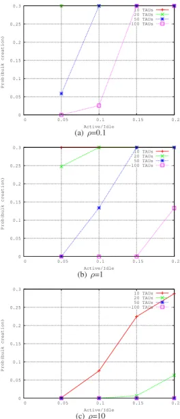
0 0.05 0.1 0.15 0.2 0.25 0.3 0 0.05 0.1 0.15 0.2 Prob(bulk creation) Active/Idle 10 TAUs 20 TAUs 50 TAUs 100 TAUs (a) ρ=0.1 0 0.05 0.1 0.15 0.2 0.25 0.3 0 0.05 0.1 0.15 0.2 Prob(bulk creation) Active/Idle 10 TAUs 20 TAUs 50 TAUs 100 TAUs (b) ρ=1 0 0.05 0.1 0.15 0.2 0.25 0.3 0 0.05 0.1 0.15 0.2 Prob(bulk creation) Active/Idle 10 TAUs 20 TAUs 50 TAUs 100 TAUs (c) ρ=10
Fig. 14. Probability of generating a bulk message after a certain time period.
From the results obtained so far, the bulk signaling-based mechanism exhibits the best performance. However, its good performance comes at the price of additional delays to the actual transmission of TAU messages, and ultimately to the reattachment of UEs to the network. In Fig. 14, we plot the probability of creating a bulk after a certain time period (T ) for three different populations of active and idle UEs (i.e., ρ=0.1, ρ=1, and ρ=10), considering four bulk sizes (i.e., 10, 20, 50 and 100 TAU messages) and assuming the high failure rate scenario. The figures clearly indicate that bulk messages are created within shorter times when there are more UEs in
idle state (i.e., small values of ρ). However, when there are
less UEs in idle state, the generation of bulk messages takes longer times; even when forming bulks with small sizes. This observation is trivial as the higher the number of idle-mode UEs sending TAU messages, the higher the probability to rapidly create a bulk message becomes. Furthermore, it is observed that the time required to create a bulk message is somehow proportional to the bulk size.
To conclude, the bulk signaling management scheme defines the best way to reduce signaling overload that may occur after restoring the failure of a MME VNF, particularly in the presence of high number of idle-mode UEs. However, if there are not that many idle-mode UEs, the profile ID-based signaling management approach could be more appealing as it does not incur any delays to the transmission of TAU messages and subsequently to UE reconnection. Its signaling overhead is also still within acceptable ranges.
VI. CONCLUSION
In this paper we devised efficient proactive restoration mechanisms to ensure service resilience in Carrier Cloud. The aim of these mechanisms is to reduce the network overload may happen due the control signaling messages issued to restore the MME VNF entity. The first mechanism is based on bulk signaling, i.e. create only one single message to replace a certain number of signaling messages in a bulk, while the second one creates message profile, i.e. reduce the signaling message header by replacing repetitive information element by a profile ID. To evaluate the performance of the devised mechanisms, an analytical model based on Markov chain is provided. Obtained results indicate the superiority of the proposed solutions compared to the current 3GPP solution.
REFERENCES
[1] “Cisco Visual Networking Index: Global Mobile Data Traffic Forecast Update , 2013-2018”, White Paper, Feb. 2014.
[2] T. Taleb, “Towards Carrier Cloud: Potential, Challenges, & Solutions,” in IEEE Wireless Communications Magazine, Vol. 21, No. 3, Jun. 2014. pp. 80-91.
[3] 3rd Generation Partnership Project, “General Packet Radio Service (GPRS) enhancements for Evolved Universal Terrestrial Radio Access Network (E-UTRAN) access,” TS 23.401, V10.2.1, Jan. 2011. [4] 3rd Generation Partnership Project, “Architecture enhancements for
non-3GPP accesses,” TS 23.402, V10.2.1, Jan. 2011.
[5] Authored by network operators, “Network Functions Virtualization: An Introduction, Benefits, Enablers, Challenges, & Call for Action,” Oct. 2012
[6] T. Taleb, M. Corici, C. Parada, A. Jamakovic, S. Ruffino, G. Karagiannis, and T. Magedanz, “EASE: EPC as a Service to Ease Mobile Core Network,” in IEEE Network Magazine. (to appear)
[7] A. Ksentini and T. Taleb, “Light Mobile Core Networks for Machine Type Communications,” to appear in IEEE Access Magazine. [8] T. Taleb and K. Samdanis, “Ensuring Service Resilience in the EPS:
MME Failure Restoration Case,” in Proc. IEEE Globecom 2011, Hous-ton, Texas, USA, Nov. 2011.
[9] 3rd Generation Partnership Project, “Restoration Procedures,” TS 23.007, V10.2.0, Dec. 2010.
[10] 3rd Generation Partnership Project, “Study of EPC Nodes Restoration,” TR 23.857, V1.2.0, Mar. 2011.
[11] T. Taleb and A. Ksentini, “On Alleviating MTC overload in EPS,” in Elsevier J. on Ad Hoc Networks, Vol. 18, Jul. 2014, pp. 24 - 39. [12] M. Scholler, M. Stiemerling, A. Ripke, and R. Bless, “Resilient
deploy-ment of virtual network functions,” in Proc. of ICUMT, St. Petersburg, Russia, Sep. 2013.
[13] A. Kunz, T. Taleb, and S. Schmid, “On Minimizing SGW/MME Relocations in LTE”, in Proc. ACM IWCMC’10, Caen, France, Jun. 2010.
[14] T. Taleb and A. Ksentini, “VECOS: A Vehicular Connection Steering Protocol,” in IEEE TRANS. on Vehicular Technology.
[15] D. Tipper, T. Dahlberg, H. Shin, C. Charnspripinyo, “Providing Fault Tolerance in Wireless Access Networks”, IEEE Communications Mag-azine, Vol.40, No.1, Jan 2002.
[16] S. Pack, T. You, T. Choi, “Performance Analysis of Robust Hierarchical Mobile IPv6 for Fault Tolerant Mobile Services”, IEICE Transactions on Communications, Vol.E87-B, No.5, May 2004.
[17] Y-F Huang, M-H Chuang, “Fault Tolerance for Home Agents in Mobile IP”, Computer Networks, Vol.50, No.18, Dec 2006.
[18] Y-B. Lin, “Per-user checkpointing for mobility database failure restora-tion”, IEEE Transactions on Mobile Computing, Vol.4 , No. 2, Mar/Apr 2005, pp.189 - 194
[19] H-N Hung, Y-B Lin, N-F Peng, S-I Sou, “Connection failure detection mechanism of UMTS charging protocol”, IEEE Transactions on Wire-less Communications, Vol.5 , No.5, May 2006 , pp.1180 - 1186 [20] J-W Lin, J. Arul, “An Efficient Fault Tolerant Approach for Mobile IP
in Wireless Systems”, IEEE Transactions on Mobile Computing, Vol.2, No.3, Jul/Sep 2003.
[21] J-W Lin, M-F Yang, “Fault-Tolerant Design for Wide-area Mobile IPv6 Net-works”, Journal of systems and Software, Vol.82, No.9, Sep 2009 [22] 3rd Generation Partnership Project, “Study on PCRF failure and
restora-tion,” TR 29.816, V10.0.0, Oct. 2010.
[23] P. Calhoun, “Diameter Base Protocol,” Network Working Group, RFC 3588, Sep. 2003.
[24] 3rd Generation Partnership Project, “E-UTRAN; Self-configuration and self-optimizing network use cases and solutions,” TR 36.902, V9.3.0, Dec. 2010.
[25] S. Dixit, E. Yanmaz, O.K. Tonguz, “On the Design of Self-Organized Cellular Wireless Networks”, IEEE Communication Magazine, Vol.43, No.7, Jul 2005.
[26] N. McKeown et al., “OpenFlow: Enabling Innovation in Campus Net-works,” SIGCOMM CCR, Vol. 38, No. 2. ACM, 2008, pp. 69-74. [27] J. Batalle et al., “On the Implementation of NFV over an OpenFlow
Infrastructure: Routing Function Virtualization,” in 2013 IEEE SDN for Future Networks and Services (SDN4FNS), Trento, Italy, Nov. 2013. [28] A. Basta et al. “A Virtual SDN-Enabled LTE EPC Architecture: A Case
Study for S-/P-Gateways Functions,” in 2013 IEEE SDN for Future Networks and Ser-vices (SDN4FNS), Trento, Italy, Nov. 2013. [29] J. Kempf et al., “Moving the Mobile Evolved Packet Core to the Cloud,”
Proc. WiMob, Barcelona, Spain, 2012.
[30] F. Yousef, J. Lessman, P. Loueiro, S. Schmid, “SoftEPC - Dynamic Instantiation of Mobile Core Network Entities for Efficient Resource Utilization”, in Proc. of IEEE ICC 2013, Budapest, Hungary, June 2013. [31] F. Machida, M. Kawato, and Y. Maeno, “Redundant virtual machine placement for fault-tolerant consolidated server clusters,” in Network Operations and Management Symposium (NOMS), 2010 IEEE, pp. 32-39, 2010.
[32] T. Taleb and Y. Hadjadj-Aoul, “QoS2: A Framework for Integrating Quality of Security with Quality of Service,” in Wiley J. on Security & Communication Networks, Vol. 5, No. 12, Dec. 2012. pp. 1462-1470. [33] EU FP7 Project, SECCRIT, URL: www.seccrit.eu
[34] R. Stewart, “Stream Control Transmission Protocol,” Network Working Group, RFC 4960, Sep. 2007
[35] T. Taleb, G. Punz, and S. Schmid, “Method for Handling Failure of a MME in a LTE/EPC Network,” European Patent” EP 2481228, May 2010.