THÈSE
En vue de l’obtention du
DOCTORAT DE L’UNIVERSITÉ DE TOULOUSE
Délivré par l'Université Toulouse 2 - Jean Jaurès
Présentée et soutenue par
Ronan BADUEL
Le 30 septembre 2019
Une approche intégrée d'ingénierie des systèmes ferroviaires
basée sur les modèles et prenant en charge leur validation
Ecole doctorale : EDMITT - Ecole Doctorale Mathématiques, Informatique et
Télécommunications de Toulouse
Spécialité : Informatique et Télécommunications
Unité de recherche :
IRIT : Institut de Recherche en Informatique de Toulouse
Thèse dirigée par
Jean-michel BRUEL et Iulian OBER
Jury
M. Vincent CHAPURLAT, Examinateur M. Ludovic APVRILLE, Examinateur
M. Marius BOZGA, Examinateur Mme Isabelle PERSEIL, Examinatrice M. Jean-michel BRUEL, Directeur de thèse
M. Iulian OBER, Co-directeur de thèse M. Drira KHALIL, Président
approach for railway systems
Acknowledgments
Though a personal work by nature, many people were involved in this thesis, and deserve to be cited. I would like to thank first Jean-Michel Bruel, Iulian Ober, Mohammad Chami and Eddy Doba, which have overseen my activities these past three years and helped me achieved my goals. I would then like to thank Vincent Chapurlat, who helped me find this thesis, reviewed it as a rapporteur and has been the professor that taught me system engineering before that. A special mention to the functional architecture team in BT. They welcomed me in the company, helped me with my work and made my period in Crespin very enjoyable. I hence thank Jerome, Samy, Laurent, Lucile, Ali, Mouhammadou, Maria, Carine, Aurelien, Emmanuel, Carlos, Delphine, Pierre and all the others in BT that helped during my time there.
I thank my family, which greatly supported me in my studies up to this Phd. A special thank to my brother, who helped proof-reading this work without counting the hours.
I finally thank the jury, who agreed to evaluate this work and provided both a serious scrutiny during the defense of the thesis and welcomed advices afterwards. I am liable to omit people, so I would like to thank the readers, be they contributors or persons interested in this work, for the value they bring to this work.
Abstract
Systems engineering is a field of study multidisciplinary by nature, using knowledge and techniques from different fields, from mathematics and computer science to organiza-tional theory. As such, it encompasses hundreds of different jobs and practices. It is a discipline used to develop complex systems, meaning systems being composed of different elements linked by relationships. While specifying, developing and validating individual components may not be an issue, doing the same for the whole system is often difficult. A complex system such as a train is developed by several teams of engineers with different viewpoints. We consider here the practice in Bombardier Transport (BT), a train manufacturing company. In BT, the functional architecture alone necessitates to be divided among different engineers, using different scopes of study. It is expressed at system level, meaning the level of abstraction of a vehicle (consist) forming a train. The system is not defined as a global element, it is induced by different pieces of information. This information is specified by several engineers or even teams of engineers, even when considering the system only as a whole without the elements composing it.
include information relative to sub-systems or components. In order to conceive the system, the information characterizing it should be expressed at system level or be linked to global properties or constraints. It means abstracting the information when possible. Considering the amount of information used to characterize a system, abstracting it helps to make it more manageable while overlooking unnecessary details which are not relevant to a global perspective. It can then be integrated into a coherent whole.
Achieving the abstraction and the integration of the information requires having traceability, so that every relevant piece of information is considered when studying the whole system. Relevant information about the whole system is taken into account when studying each of its parts. The notion of relevance mentioned here means that it has an impact on the part that is currently studied. For example, a train, which is a whole system, will generally not move if one of its doors, which is a component, is open. On the other hand, a door component will not open if the whole train is moving. In this example, with the train being considered as a complex system, information regarding each individual door will not be considered when studying the train as a whole, just as a door will not receive information regarding characterizing the train as a whole. It is however necessary to express, correlate and trace information between different levels of abstraction to know and/or specify a system and its behavior.
The goal pursued in this thesis is to provide a method to integrate information re-garding a train system during the design phase, enabling the specification, representation and validation of its behavior. To this end, several solutions are developed: concepts characterizing the system and its behaviors are developed and applied in models. The way the models are created and the information expressed through them is automatically checked using verification rules. The information and the models are then integrated. The integration is specified and checked using constraints and properties based on the system concepts developed.
R´
esum´
e
L’ing´enierie syst`eme est par nature un domaine d’´etude multidisciplinaire. Elle fait appel `
a des connaissances et des techniques d’origines vari´ees, allant des math´ematiques et de l’informatique `a la th´eorie de l’organisation. Ainsi, elle couvre des centaines de m´etiers et de pratiques diff´erents. C’est une discipline employ´ee pour d´evelopper des syst`emes, c’est-`a-dire des ensembles compos´es de diff´erents ´el´ements li´es par des relations. Bien que sp´ecifier, d´evelopper et valider chacun de ces ´el´ements s´epar´ement soit r´ealisable, faire de mˆeme pour le syst`eme dans sa globalit´e est souvent difficile.
Un syst`eme complexe tel qu’un train est d´evelopp´e par diff´erentes ´equipes d’ing´enieurs, chacune adoptant un point de vue diff´erent. On s’int´eresse ici aux pratiques au sein de Bombardier Transport (BT), une entreprise fabriquant des trains. A lui seul, le d´eveloppement d’une architecture fonctionnelle d’un train au sein de BT n´ecessite de r´epartir le travail entre diff´erents ing´enieurs, chacun s’int´eressant `a un cadre d’´etude par-ticulier. Une telle architecture est consid´er´ee au niveau d’abstraction du syst`eme ´etudi´e, qui est un v´ehicule formant un train ou une partie de train. Le syst`eme n’est alors pas d´efini comme un ensemble global, il est induit par diff´erentes informations. Celles-ci sont fournies par diff´erents ing´enieurs ou ´equipes d’ing´enieurs, quand bien mˆeme on s’int´eresse au syst`eme et non pas aux ´el´ements qui le composent.
Les exigences, c’est-`a-dire les attentes exprim´ees vis-`a-vis du syst`eme, comprennent g´en´eralement des informations relatives `a ses sous-syst`emes ou ses composants. Pour concevoir un syst`eme, les informations qui le caract´erisent doivent ˆetre exprim´ees `a son propre niveau d’abstraction ou bien ˆetre li´ees `a des propri´et´es ou contraintes globales qui lui sont propres. Cela demande d’abstraire les ´el´ements d’information chaque fois que cela est possible. Etant donn´e la quantit´e d’informations relatives au syst`eme, les abstraire facilite ainsi leur gestion tout en occultant les d´etails superflus. On peut alors les int´egrer au sein d’un tout coh´erent.
Abstraire et int´egrer les informations relatives au syst`eme n´ecessite de pouvoir les tracer, de fa¸con `a ce que toute information pertinente soit prise en compte lors de l’´etude du syst`eme global, et que toute information pertinente issue du syst`eme global soit prise en compte lors de l’´etude d’un des ´el´ements qui le compose. La notion de pertinence exprim´ee ici se rapporte `a l’impact que cela peut avoir sur l’objet ´etudi´e.
Un train, en tant que syst`eme global, ne pourra g´en´eralement pas bouger si l’une de ses portes, ´etant donc un de ses composants, est ouverte. De la mˆeme fa¸con, une porte, en tant que composant, ne pourra pas s’ouvrir si le train est en mouvement. On voit ainsi que l’´etude du train dans son ensemble ne tient pas compte des informations sp´ecifiques `a chaque porte, tout comme chaque porte ne consid`ere pas l’ensemble des informations caract´erisant le train. Il est en revanche n´ecessaire d’exprimer, corr´eler et tracer les informations entre les diff´erents niveaux d’abstractions pour connaˆıtre et/ou sp´ecifier un syst`eme et son comportement.
Le but de la th`ese pr´esent´ee ici est de fournir une m´ethode permettant d’int´egrer les informations caract´erisant un syst`eme de train au fur et `a mesure de sa conception, permettant ainsi la sp´ecification, la repr´esentation et la validation de son comporte-ment. Pour ce faire, diff´erentes solutions sont d´evelopp´ees : des concepts caract´erisant le syst`eme et son comportement sont d´evelopp´es et appliqu´es au sein de mod`eles. La fa¸con dont les mod`eles sont cr´e´es et dont les informations dont exprim´ees `a travers eux est v´erifi´ee automatiquement `a l’aide de r`egles de v´erification. Les informations et les mod`eles sont alors int´egr´es. L’int´egration elle-mˆeme est sp´ecifi´ee et v´erifi´ee `a l’aide de contraintes et de propri´et´es bas´ees sur les concepts d´evelopp´es vis-`a-vis du syst`eme.
Abbreviations
BDD: Block Definition Diagram BT: Bombardier Transport
BT SysMM: Bombardier Transport Modeling Method DITLOTT: Day In The Life-cycle Of The Train DSML: Domain Specific Modeling Language FA: Functional Analysis
FB: Functional Block
FBS: Functional Breakdown Structure FC: Functional Context
FMI: Functional Mock-up Interface FMU: Functional Mock-up Unit HIL: Hardware In the Loop HMI: Human Machine Interface HW: Hardware
IBD: Internal Block Diagram OA: Operational Analysis OB: Operability Analysis
OBS: Operational Breakdown Structure OMG: Object Management Group MIL: Model In the Loop
SHL: System Hierarchical Level PI: Product Introduction
RBS: Requirement Breakdown Structure SIL: Software In the Loop
SysMM: System Modeling Method SW: Software
TA: Technical Analysis
TCMS: Train Control Management System T0: Train 0
VB: Virtual Bird
V&V: Verification and Validation WBS: Work Breakdown Structure
1 Introduction 12
1.1 Context . . . 12
1.2 Needs . . . 14
1.2.1 Specify the train behavior . . . 14
1.2.2 Check the specifications for errors . . . 15
1.2.3 Enable communication of information between engineering teams . 17 1.2.4 Summary of needs . . . 19
1.3 Challenges . . . 20
1.4 Target . . . 23
1.5 Contributions . . . 26
1.6 Organization of the thesis . . . 27
I Problem analysis 28 2 Context 29 2.1 Bombardier Transport Modeling Method . . . 29
2.1.1 BT SysMM overview . . . 29
2.1.2 Operability . . . 35
2.1.3 System development at consist level . . . 46
2.2 Verification and validation process in BT . . . 50
2.2.1 Organization . . . 51
2.2.2 MIL: Cameo SysML . . . 52
2.2.3 SIL: Virtual Bird . . . 56
2.2.4 HIL: TRAIN0 . . . 58
2.3 Needs analysis . . . 59
2.3.1 List of issues . . . 59
2.3.2 Derived needs . . . 62
2.4 State of the art . . . 63
2.4.1 Specifying the train behavior . . . 63
2.4.2 Checking the specifications for errors . . . 65
2.4.3 Enabling communication of information between engineering teams 67 2.5 Contributions . . . 68
2.5.1 Concepts of states and modes . . . 68
2.5.2 Model verification method . . . 69
2.5.3 Behavior verification method and model . . . 69
3 Background: system theory and engineering 70 3.1 System theory and definition . . . 71
3.1.1 System concept . . . 71
3.1.2 System representation . . . 75
3.1.3 Method . . . 77
3.2 Systems engineering . . . 78
3.2.2 System representation . . . 81
3.2.3 Method . . . 84
3.3 Synthesis . . . 85
II Contributions 87 4 Concepts of states and modes 88 4.1 Concept of State . . . 90
4.1.1 State of the art . . . 90
4.1.2 Analysis . . . 91
4.1.3 Definition . . . 93
4.1.4 Example . . . 95
4.2 Concept of Mode . . . 95
4.2.1 State of the art . . . 95
4.2.2 Analysis . . . 96
4.2.3 Definition . . . 98
4.2.4 Example . . . 99
4.3 Application . . . 99
4.3.1 Definition of train states . . . 99
4.3.2 Definition of train modes . . . 103
4.3.3 Verification of the behavior . . . 106
5 Model verification method 107 5.1 Models V&V . . . 107
5.3 State of the art . . . 109
5.4 BT SysMM V&V . . . 110
5.4.1 Method Stakeholders . . . 110
5.4.2 V&V Method Overview . . . 114
5.4.3 Benefits . . . 116
5.5 Use case example . . . 117
6 Behavior verification method and model 120 6.1 Presentation . . . 120 6.1.1 Context . . . 120 6.1.2 Issues . . . 121 6.1.3 Related works . . . 122 6.1.4 Method . . . 123 6.1.5 Case study . . . 123
6.2 Behavior description through states . . . 123
6.2.1 States in the case study . . . 123
6.2.2 State constraints . . . 124
6.2.3 State constraints in the case study . . . 126
6.2.4 Use case pre-conditions . . . 127
6.2.5 Use case pre-conditions in the case study . . . 128
6.3 Verification method . . . 128
6.3.1 State constraints verification . . . 129
6.3.2 Use case preconditions verification . . . 130
6.3.3 Results . . . 130
6.4.1 Holonic structure for states . . . 132
6.4.2 Structure of the behavior . . . 135
6.4.3 Structure of modes in the case study . . . 137
6.5 Synthesis . . . 138
6.5.1 Method . . . 138
6.5.2 Traceability . . . 138
7 Conclusion 140 7.1 Contributions synthesis . . . 140
7.1.1 Concepts of states and modes . . . 140
7.1.2 Model verification method . . . 141
7.1.3 Behavior verification method and model . . . 143
7.2 Impact of the global solution . . . 144
7.2.1 Progress toward the overall objective of BT . . . 144
7.2.2 Consequences on BT . . . 145
7.2.3 Consequences on MBSE . . . 145
7.3 Future work . . . 146
7.3.1 Remaining work to be done in the company . . . 146
Introduction
This PhD provides solutions to specify, integrate and verify a train system behavior. In this introduction, the context of the work is explained, as well as the problematic that led to the development of the solutions presented in the next part.
1.1
Context
The work presented here results from a research project conducted in the industry and require some context. Bombardier Transport (BT), a train manufacturer, has been developing its systems engineering practice for several years, increasing the use of models, tools and general methods. BT is a big company of more than thirty thousand people that focuses its activity on six main implementations all around the world. Albeit being one of the leading company in train manufacturing, it faces a strong competition, and has an increasing need to save time and money while improving the quality of its products to satisfy the clients requirements. In order to get a contract, BT often has to be the quickest to deliver a product. This requires to build a satisfactory product the first time, or to face delay penalties otherwise.
We can summarize the current goals of BT as follows:
• Avoiding delay penalties.
• Limiting the number of iterations during the development of a train product. • Providing higher quality products that meet the clients’ expectations.
The problem considered here does not deal with the product itself, but the way it is developed. The Train technologies and components have remained roughly the same for the last decade, so the main part in developing or adapting a product relates to the specification of functions. A function is something performed by a train, taking inputs and providing outputs. A functional architecture is a hierarchical arrangement of func-tions [1]. Its definition leads to the choice and integration of adequate, often pre-existing components. The issue for BT is hence to specify what the train must do, when, and how. The object of study is hence the behavior resulting from the functional architecture being developed. Interviewing BT’s engineers, it appeared that the concept of behavior could be understood as “the peculiar reaction of a thing under given circumstances”, which is one of the definition given in the standard ISO/IEC/IEEE 24765 [1].
The current development process has an issue: the concept of behavior is understood but not formally defined in BT. The behavior of a train system as a whole is hence not specified, it is first induced by requirements and individual specifications, and later on by the design. One could say that the system and its behavior only exist in the engineers’ minds, using their experience and knowledge.
Information regarding the train behavior exists but needs to be captured. Since the development of a train is based on its functions and behaviors, engineers have to manipulate abstract information. Be it communicating specifications or searching for errors, the information contained must be correctly represented and understood by all. This is an issue in BT, as a same train project can involves development teams from different departments, countries or companies. Information actually represented can be expressed differently depending on the tool, the method, the language or the point of view adopted. This can lead to loss of information, misunderstanding or inconsistencies. Clients and company requirements regarding the solution have to be taken into ac-count all along the development process. The current tendency for the development of a design is to favor the reutilization of requirements, specifications and existing solutions whenever possible. BT is currently developing product families from which existing so-lutions can be chosen and adapted depending on the project. This once again requires a way to formalize and represent knowledge regarding the train and its behavior.
The kind of issues presented here lead BT to adopt, develop and improve Model-Based Systems Engineering (MBSE) [2] solutions, using SysML [3]. MBSE is the current and favored approach to the development of complex system [4], supported by research work and opportunities, which is why it is considered as a solution to BT needs and problems.
BT has developed a modeling method regarding the functional specification of a train system, the BT System Modeling Method (BT SysMM) [5], which is implemented through a SysML profile. This method is based on the standard ISO/IEC/IEEE 15288-2015 [6] as well as studies done to develop functional architecture with SysML [7]. BT SysMM is presented in further details in the chapter 2.
To reach the goals previously listed, BT needs to improve its development process. This requires to satisfy the following needs:
N 1. Specify the train behavior.
N 2. Check the specifications for errors.
N 3. Enable communication of information between engineering teams.
Those needs will be satisfied by solutions developed in an MBSE context, compatible with SysML and improving or completing the BT SysMM.
1.2
Needs
We analyze in this section the global needs of BT and decompose them into a list of detailed needs to be satisfied by the solutions developed.
1.2.1 Specify the train behavior
We first consider the specifications relating to the train behavior. Elements of the behav-ior are specified using scenarios and use cases. Scenarios are ”step-by-step description of a series of events that occur concurrently or sequentially” [1]. In BT, they are expressed using activity diagrams and sequence diagrams, or even drawn without an official mod-eling language. They correspond to sequences of operations performed in interactions with users and external systems. Those operations are called use cases. They correlate with services or capabilities performed by the train from the users’ point of view. Use cases are specified using requirements, activities or the actual use case SysML element. They are defined independently from the scenarios: a same use case can be mentioned in different scenarios.
A scenario corresponds to an intended utilization of a train system and is used to model sequence of use cases performed in a given set of circumstances, meaning the situation the system is in. Scenarios do not cover all possible utilizations of the train, and the circumstances they express are neither formal nor exhaustive.
A scenario can be considered as a piece of the train potential behavior. Depending on how the execution of the use cases is constrained and the design satisfies the behavior specified in the scenarios, we can obtain different train behaviors: integrating different behavior results in new ones, through the phenomenon of emergence [8].
Information on the circumstances of realization of the use cases and their integration into a global behavior is either incomplete, induced or “hidden” in textual requirements or specific models such as scenarios, which have limited scope. For example, a use case can indicate how to change the speed of windscreen wipers, and another to activate windscreen wipers for a duration after triggering a washing mechanism. In the model and documentation, there is nothing that says at which speed the wipers should be set at after washing, if there is a need for a timed activation if the wipers were already activated, etc. The example is trivial, and may be contained in a specific scope, but it is symptomatic of a lack of integration of the train capabilities.
The integration itself leads to the specification, comparison and prioritization of capabilities depending on the circumstances. We need to complete the existing modeling method with models enabling to specify and integrate the whole system behavior. Based on current specifications regarding the behavior, there is a need to:
N 1.1. Specify dynamic aspects between use cases.
N 1.2. Correlate the information expressed in different scenarios and use cases. N 1.3. Formalize the circumstances enabling the execution of each use case.
1.2.2 Check the specifications for errors
We now consider the second objective, which relates to detecting errors in the specifi-cations. In order to make a good product on the first try, errors have to be avoided or detected early. A general observation in the industry is that the later an error is detected, the more the cost [9]. This is why current solutions and improvements focus on the early stage of a train’s design. There are two aspects to consider when checking if the specifications are correct or not: it is necessary to check (i) whether the specifications are consistent with a train product; and (ii) whether the obtained product satisfies the initial expectations. This ’checking’ process corresponds to two kinds of activities called verification and validation.
Verification and validation are two concepts frequently used in systems engineering, and need to be defined. By default, the terms used in this thesis correspond to the definitions provided in the x ISO/IEC/IEEE 24765 standard on systems engineering vocabulary [1]. We define here the terms of V&V using the common definition and understanding of these concepts [10]:
• Verification: answering the question ”are we building the system right?” • Validation: answering the question ”are we building the right system?”
Figure 1.1: BT current validation process
We consider now BT’s current validation process, illustrated in Figure 1.1. It fol-lows three steps: Model In the Loop (MIL), Software In the Loop (SIL) and Hardware in the Loop (HIL). MIL is a validation conducted on a co-simulation through SysML models. SIL is performed on the developed software and emulated hardware through co-simulation. HIL is performed either on a bench test or a real train.
BT aims for a tool chained method that provided V&V solutions for MIL, SIL and HIL steps of the validation process. The method should focus on filling the gap between each of these steps so as to ensure traceability and continuity of the validation. SIL and HIL already having V&V solutions working, though not fully developed yet, the second objective was to develop a way to verify and validate the behavior based on SysML models, which are themselves developed over several steps following BT SysMM.
BT currently checks whether a train system performs the expected functions or not, using tests. Checking that the train behaves as expected, meaning that it can perform the right functions in the right circumstances is the responsibility of the functional engineers. They check behaviors that are part of the expected utilization of the system, expressed using scenarios. This can be done by means of execution or simulation on a co-simulation or a bench test, that other teams are in charge of developing.
Understanding the system as a whole and knowing how it should behave is something that is checked by engineers through their knowledge and experience, as well as their understanding of the requirements. There is no formal validation method regarding the behavior, engineers rely on manual execution or tests created from scenarios and their experience to evaluate whether the system is well-made and satisfactory or not. Just as all possible dynamics between different capabilities may not have been specified, they may not be verified and validated either. There are no formal requirements on what should be validated regarding the behavior.
We can summarize the needs for the system behavior V&V as follows:
N 2.1. Define V&V requirements for the integrated system behavior N 2.2. Provide V&V solutions of the behavior based on SysML models
N 2.3. Ensure traceability and continuity of specifications and validation results N 2.4. Fill the gaps between tools, models and development steps
1.2.3 Enable communication of information between engineering teams The definitions provided earlier are only relevant when talking about a system, here the train. As there a need to properly represent and communicate information regarding the system, there is a need to ensure that those representations are well made and correspond to expectations of the people receiving and using them. In an MBSE context, those representations are models. There is hence the need to verify and validate models, not the system itself. We will hence talk of system V&V, and model V&V. In the case of model V&V, we use the definitions of the IEEE 1012-2012 standard [11]:
• Verification: ensuring that the models created have been correctly built.
• Validation: ensuring that the system represented by the models matches the re-quirements traced to the information displayed or induced.
As there is a need for the exchange and reuse of information, there is a need to check that any kind of model created as part of the development process will be created and understood in the same way by any engineer. This implies to verify the model. A modeling language comes with its own rules which force the model to be constrained and avoid ambiguity in the way it is built. Beyond the fact that the models are correct, the chosen modeling language has to carry a unique semantics regarding the real system characterized by the models. This is not validation, this is verification, i.e., the semantic is not checked but rather the models are verified with respect to the semantic rules of the chosen modeling language.
We come back to the need to formalize information in models. Concepts have to be expressed to characterize the real system and its behavior. Defining all concepts to be used means creating an ontology. An ontology is a ”logical structure of the terms used to describe a domain of knowledge” [1]. Van Ruijven explains the needs of ontology in MBSE [12]. Supposing the creation of a formal ontology is achieved, there is a need to verify the model accordingly, to see if its elements properly express the corresponding concepts.
Any verification solution will have to be deployed and used in all BT implementations. It shall be used to standardize the way models are created and understood. It hence has to be part of BT SysMM.
The needs toward enabling proper communication of a train specifications in BT can be listed as follows:
N 3.1. Define an ontology that enables us to express system concepts in all models N 3.2. Develop a model verification solution according to the ontology and modeling
method provided
1.2.4 Summary of needs We obtain the following list of needs:
N 1. Specifying the train behavior.
N 1.1. Specify dynamic aspects between use cases.
N 1.2. Correlate the information expressed in different scenarios and use cases. N 1.3. Formalize the circumstances enabling the execution of each use case. N 2. Checking the specifications for errors.
N 2.1. Define V&V requirements for the integrated system behavior N 2.2. Provide V&V solutions of the behavior based on SySML models
N 2.3. Ensure traceability and continuity of specifications and validation results N 2.4. Fill the gap between tools, models and development steps
N 3. Enabling communication of information between engineering teams.
N 3.1. Define an ontology that enables us to express system concepts in all models N 3.2. Develop a model verification solution according to the ontology and
mod-eling method provided
N 3.3. Implement the solution in a method supporting the system development
Before addressing those needs, it is necessary to consider the scope in which solutions must be developed and what are the constraints and limitations to consider. More importantly, we have to identify the challenges toward solving BT issues. Such challenges will be linked to current research work in MBSE.
1.3
Challenges
In this section, we link the needs of BT to scientific challenges in MBSE. We reference several sources to sum up the challenges faced in an MBSE approach.
Figure 1.2: INCOSE MBSE roadmap [4]
We mainly refer to the MBSE roadmap, shown in Figure 1.2. This roadmap shows that MBSE is evolving and has yet to reach maturity. Developing and adapting MBSE solutions for a company is in itself a challenge [13]. BT needs correspond to the need for a well-defined MBSE, as described in the roadmap.
The issues encountered in BT can be compared to those addressed by Ingham [14]:
• Sub-system-level functional decomposition fails to express the whole system be-havior.
• There is a gap between the requirements and their implementation. • The system behavior is not always explicitly specified.
The first challenge presented by Ingham can be linked to the notion of emergence we presented earlier. The second can be linked to the needs in BT N 2.3. and N 3., as the proper information must be traced and communicated. The third correspond to the need N 1.
BT needs to verify and validate train systems behavior. Works [15, 16, 17] show that one should specify, and if possible validate, the expected behavior of the system as a whole using requirements and scenarios, before any design or implementation. The main issue encountered to achieve such a task is that a model of the system is required to define and support the behavior. The lack of a formal description of the system at specification level prevents its automatic verification [18]. Rather than just specifying what the system-to-be does, we have to specify “what” system we want to obtain [18]. Having an integrated model of the system at the early step of design is a challenge.
We can see in [19] that requirements tend to be textual-based. Using models to express requirements is not a common practice, as explained in [20]. Developing an MBSE approach for requirements engineering is a challenge [21]. Furthermore, SysML, which is the language we want to use here, manipulates requirements as blocks with textual properties. New ways to use SysML elements have to be created in order to specify requirements in models, as presented in [20].
How to perform validation on system behavior is a field of research in systems engi-neering [22]. Studies that show that the issues considered in BT are parts of different challenges that are rarely or ill-resolved in common solutions. For example, emergent behavior, differences in granularity of the information or the fact that implementation details can pollute the model are discussed in [23]. The issue regarding various levels of detail regarding the specifications is also highlighted in [16].
Another study [24] explains that validation is seldom attempted regarding the dy-namics of a system, and mentions incomplete information as a source of uncertainty when modeling and validating complex systems. Information can be found partially in the requirements, but it is often incomplete. Supposing the information is available, it needs to be correctly integrated in models to be useful. Having an MBSE solution enabling to transmit information from requirements to a functional architecture is a challenge, as explained in [25].
The difficulties encountered can be linked to a current research topic that is early validation [26, ?]. The integration and application of different V&V solutions in the overall development and modeling process is also an issue [27]. The same study highlights the issue of expressing and continuously checking system properties through different or evolving models, which can be linked to BT needs in terms of V&V requirements and traceability.
As mentioned in the need N 3.1., an ontology is necessary to enable communication and consistency of the specifications in the models. Van Ruijven explains the needs of ontology in MBSE [12], arguing that a standard ontology for MBSE has yet to be defined and the ones used in practice lack consistency. This is supported by the MBSE roadmap defined by the INCOSE, presenting the need for an MBSE theory and ontology to be considered by the year 2020.
We summarize the challenges as follows:
C 1. Having an integrated model of the system at the early stage of design.
C 2. Making use of SysML elements to specify requirements regarding the system be-havior.
C 3. Anticipating and/or managing the emergence phenomenon in the behavior. C 4. Formalizing, completing and standardizing information in the specifications. C 5. Integrating and applying V&V solutions in the overall development and modeling
process.
C 6. Expressing and continuously checking system properties through different or evolv-ing models.
C 7. Supporting the MBSE approach by a formal ontology
The way the needs previously expressed are linked to the challenges identified is given in the Figure 1.3.
Figure 1.3: Links between BT needs and identified research challenges
1.4
Target
All the challenges presented in the previous section will not be solved in this thesis, in part because there are independent teams in BT that are responsible for some of them. The rest is due to the limitations on the scope of the thesis to keep the issues manageable and relevant to the company. We provide the scope in which solutions are to be developed as well as limitations and constraints to take into account.
We consider issues and limitations from different points of view, resulting in the definition of seven domains that we will discuss in this thesis:
• Ontology. • Semantic. • Integration. • Specification.
• Verification & Validation. • Traceability.
• Modeling.
“Method” and “MBSE” are not mentioned in these domains as it overlaps with the method that we are currently trying to define, as part of an MBSE solution to the issues identified. As such, the domains are used to characterizes the different solutions, goals and benefits of the developed method.
The solutions to be developed will support the BT SysMM. BT SysMM is deployed and used by the functional architecture department, responsible for functional specifi-cations of the whole train. Engineers belonging to this team are working closely with requirements engineers. The functional architecture department provides specifications to the teams or external suppliers working on the sub-systems of the train. They also work with teams working on verification and validation of the whole train system, taking part in the process. This study is hence centered on the role and work of the functional architecture department. Specifications and models will be provided to the validation department.
According to the Figure 1.1 and according to the need N 2.4., there is a need to interface V&V tools and enable the exchange of models. However, the SIL and HIL solutions are outside the scope of this study. Furthermore, the methods and models used in SIL are still in development, while the use of SysML models in MIL has been confirmed. The first step in bridging the gap between a tool and V&V steps of the validation process is to define and formalize information regarding the behavior and the criteria used to check it. It is why the solutions developed focus on the SysML models, specifications and requirements to be transmitted and not the technical aspects, which are already studied by the validation team. The need N 2.4. will be covered by specifying the specifications and validation requirements to be transmitted.
Each functional architect is responsible for the specification, design, verification and validation of the system regarding his own scope. They are responsible for the global functional design along the development process. This is why the focus is put here on the definition of the upper layer of the system representation, which is the more abstract way to represent a train. The information manipulated can however be defined with various levels of abstraction.
A level of abstraction is a ”view of an object at a specific level of detail” [1]. We consider four levels of abstraction: train, system, sub-system, component. Expressing information at system level means the information will not mention sub-systems or components. For example, the energy supply of a train characterizes the train, but it could mention the status of the batteries of the train, which are components. At train level, it would mention the train internal energy supply, without specifying any element at a lower level of abstraction, such as batteries.
Developing sub-systems is often the responsibility of external suppliers. As functional architects are responsible for specifying the behavior, not the physical architecture, they should manipulate information at train or system level, not lower. Sub-systems are defined as abstract entities and treated as black boxes. The solutions developed will focus on the system level or higher regarding the object of study and the information manipulated.
BT SysMM is supported by a SysML profile. Concepts have already been defined regarding the semantics associated to the modeling elements. Rather than developing a full ontology as specified by the need N 3.1., only concepts needed to represent a system and its behavior will be defined.
We summarize the scope of the solutions as follows:
• Methods, solutions and models are developed for the functional architecture de-partment.
• Specifications and models will be provided to the validation department. • V&V solutions are developed for MIL only.
• Studied information will be at the system level of abstraction or higher. • Solutions will be compatible will SysML models and BT SysMM method. • New concepts will directly characterize the system and its behavior.
1.5
Contributions
This thesis is organized around three main contributions, answering the needs of BT and providing answers to the related challenges.
The first contribution relates to the definition of the state and mode concepts, with the goal to model a system and it behavior. We define the concept of state to describe a system and the circumstances it is in at a given time. The concept of mode is defined in order to specify the behavior by linking actions to circumstances enabling to perform them. All of this is addressed in chapter 4.
The second contribution presents a solution to check SysML models for errors. A method is developed to create rules. These rules are short scripts that enable to check all instances of a SysML modeling element in a project. Any property, attribute and re-lationship can then be identified by a rule and compared to one or several criteria. Using such rules to constrain the way SysML elements are used, it is possible to automatically check models created by engineers for errors with respect to a modeling method. Based on the SysML profile of the BT SysMM, rules were created to check the semantics behind models, ensuring that engineers create the same models the same way, enabling their communication and reuse. This is presented in the chapter 5.
The third contribution uses the concepts of state and mode provided in chapter 4 to describe the system, correlate the information, precondition the use cases, perform verification activities on the behavior and generate a structure for the model of the system behavior. This is detailed in the chapter 6.
1.6
Organization of the thesis
This thesis is organized in two parts. The first part is an analysis of the issue. The chapter 2 presents the context of this work and the solutions used by BT, as well as their limitations, to conclude on a list of needs to be satisfied by the solution developed. The chapter 3 presents and comments the general system theory and current issues in systems engineering, to position this work regarding the state of the art and the challenges it addresses.
The second part presents the contributions. The chapter 4 proposes an innovative definition of the concepts of states and modes, used to characterize and model a system. The chapter 5 presents a method to verify SysML models to enforce semantics specific to BT company. The chapter 6 presents a behavior verification method which leverages the concepts of states and modes to integrate and verify train system behavior at a high level of abstraction. The chapter 7 summarizes the contributions and their deployment in the company, and discusses research and industrial opportunities to explore.
The annexes contain references and examples of some of the solutions deployed in the company.
Problem analysis
Context
This thesis has been conducted inside a team of functional engineers, in collaboration with experts from different sites of the company (France, Germany, England, Canada) in charge of developing the BT system modeling method for the train functional specifi-cations. This modeling method is applied on full scale projects but is still being worked on, as it requires improvements.
This chapter presents the Bombardier Transport System Modeling Method (BT SysMM) the validation process and solutions in BT regarding the train behavior.
2.1
Bombardier Transport Modeling Method
We presents in this section the BT SysMM. We first provide an overview of the method and the context in which it is deployed. We then present in more details the operability analysis, performed at train level, and the operational, functional and technical analysis performed at system level.
2.1.1 BT SysMM overview Work Breakdown Structure
BT projects are conducted based on the general Work Breakdown Structure (WBS) [28], shown in Figure 2.1. A WBS is a structure that describes the work to do in the project. All nodes of this structure are linked to work packages containing the details of inputs, outputs, work activities and milestones in each work domain.
Figure 2.1: The BT General Breakdown Structure [28]
All projects are different, and so are their WBS. Nevertheless, in order to ensure consistency, compatibility and communication, each WBS is built around the same base, which is the general WBS. The focus is put here on the design method, meaning only a few work packages are considered. They are highlighted in Figure 2.2. Our goal is to study how the behavior is specified through use cases, scenarios and functions.
Global modeling approach
Figure 2.3: System Hierarchy Level (SHL) for the train design [29]
Each project in BT is developed starting from the highest level of abstraction to the lowest. The current working level is called the System Hierarchy Level (SHL). The train is first considered as a whole, described as a black box, then it is divided into systems corresponding to consists. A consist is an independent element of a train, also called vehicle. The train can be constituted of one or several consists, each divided into subsystems, themselves divided into components.
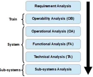
The Figure 2.3 describes the hierarchy of the train system elements. This hierarchy allows to decompose the development process of the train into more manageable steps, lowering the level of abstraction of the information considered and restricting the scope of study as we descend into its levels. The element considered at each step of the process, for example a consist or one of the subsystems, is called the System Of Interest. This SOI is the target of the modeling effort and define the scope of the element to consider. We are interested here in the development of the system behavior, from the definition of operational scenarios to the definition of a functional architecture. This is done first in the operability analysis (OB) performed at train level, and then at the system (con-sist) level through three consecutive steps: the operational analysis (OA), the function analysis (FA) and the technical analysis (TA).
BT SysMM follows the ISO 15288 standard [6], where a technical process is defined around successive steps. Specifying the system behavior and functional architecture would be done at the following steps:
• Stakeholder needs & requirements definition process. • System requirements process.
Figure 2.4: Train development process
Requirements analysis in BT corresponds to the first step. The train operability analysis is the second steps, used as a junction between requirements analysis and con-sist analysis, which comes next. The corresponding development process is shown in Figure 2.4.
Figure 2.5: Requirement Breakdown Structure (RBS)
The train development process is driven by requirements. All development steps receive requirements as inputs and generate requirements as outputs. Requirements are classified according to categories and the SOI they qualify. This classification is called the Requirement Breakdown Structure (RBS), shown in Figure 2.5.
Figure 2.6: Requirement driven design process [29]
The traceability and refinement of requirements is shown in Figure 2.6. The terms 0R, 1P, 2F, 3A do not correspond to development steps but to the classification of the requirements associated to or specified in it. For example, functional requirements will be expressed or traced in OA, FA and TA while being classified in 2F. The arrows correspond to traceability links between requirements.
Traceability is keeping track of information as it is refined or used in different mod-eling elements or documents. Refined requirements are traced to the initial ones. Ar-chitecture and functional elements can be traced to performance requirements linked to them, supposing they have some.
The traceability should be enforced between requirements, but tends to be lost through the modeling activities, as the requirements are traced to models. New re-quirements are obtained after several steps of modeling, making it hard to keep track of the initial requirements. We identify the following issue:
I 1. Requirements traceability is lost between modeling steps.
The Operability analysis (OB) step concerns the analysis of the utilization of the train, according to the requirements. Scenarios regarding the operations performed with the train are specified, then detailed as sequences of train activities which will correspond to use cases later in the process.
The functions are defined on the consist level, then linked to the subsystems in an architecture. The subsystems are then developed. Definition of the physical architecture and development of the subsystems are separate activities that are not covered in this study. At each level, a three-step development process is applied. Those three steps are presented in the next section.
The three-step modeling approach: OA, FA, TA
The system development in BT is done around a three-step approach at different hier-archical levels (Figure 2.4): Operational analysis (OA), Functional Analysis (FA) and Technical Analysis (TA). In practice, these steps are not assigned to a specific team.
The definition of functions, however, is performed by a team of functional architects and is supported by existing modeling methods. This analysis is conducted at the system (consist) level. The modeling method associated can be decomposed into the Operation Analysis (OA) and the Functional Analysis (FA). The Technical Analysis (TA) is in majority performed by another team dealing with the system architecture. While the same modeling method can in theory be applied to subsystems or even components, those are developed by either dedicated teams or external providers which often possess their own methods or models. They work more independently and are not considered in the scope of this study.
Regarding the specifications of functions at system level, the three steps can be defined as such:
• The OA aims to describing the behavior of the SOI from an external point of view. Its interactions with its environment are modeled, as well as the tasks it performs for the users or linked elements, which translate as use cases or functions.
• The FA aims to match uses cases and interactions to global functions, in order to build a functional architecture. Exchanges between those global functions are modeled, defining the internal mechanisms of the system.
• The TA corresponds for the main part to others activities such as defining the logi-cal and/or physilogi-cal architecture, as well as studying the variability in the available components (eg. different brands of batteries). It relates to the work of the func-tional architects when allocating functions to structural elements.
Development process and validation activities
The validation activities are generally performed along the modeling process. BT wishes to improve those activities and group them as a global tooled method. The Figure 1.1 presented in the introduction shows the validation process currently used by BT, as well as the solutions to be developed or integrated.
2.1.2 Operability
The goal of operability is to specify the behavior of the train at its own level of granu-larity. We define granularity as the level of details of the information specified, following the same decomposition as the SHL: train, consist, subsystem, components. Informa-tions should be set at a suitable level, generally the one of the SOI. In current practice in BT, the whole train can be set as a SOI, and be used to attach low level informations. This is something we try to avoid:
I 2. The specified information is too detailed for high-level SOIs.
Operability analysis (OB) is the most crucial step in our study, as it is where the expected system and its behavior can and should be specified through the integration of the expectations into a coherent whole. The OB is a step between requirements analysis and operational analysis (OA), as shown in Figure 2.4. Following this process, the requirements from 0R are divided into three categories: architecture (3A), functions (2F) and performances (1P).
The focus given on the functional aspect of the operability analysis, which enables the transition from the functional requirements captured, analyzed and formatted in the requirements analysis and classified as 0R, to those specified in the functional analysis, refined and classified as 2F.
Concept of Operability
Operability was a concept first developed to express the analysis done at train level when performing the requirements analysis [30]. The objectives of the operability analysis can be summarized as follows:
• Analyze and complete 0R functional requirements to derive them as 2F require-ments.
• Define all planned utilization of the system through scenarios and use cases. • Describe the train situation and capabilities through its life-cycle.
• Integrate use cases and scenarios into a global behavior.
Operability is initially a requirement driven process, with requirements as inputs and outputs. It was originally performed on DOORS [31], the tool used to manage the requirements.
The operability concept in BT is inspired by the ANSI/AIAA G-043 A-2012 standard [32]. According to this standard, there is a need to develop an Operational Concept Document (OCD) that, among others things:
• Provides a clear vision of the intended uses and the resulting benefits of the system. • Provides the basis for system validation.
Method
There is no current official method in BT for operability analysis, as it is a work in progress. Several attempted versions of a modeling method have been made [33, 34, 35], and constitute iterations toward a working method. The main issue is that there is a lack of system concepts, preventing a formalization of the models and of the information they should contain. A fourth method is currently under development.
I 3. There is no modeling method for the specification of the expected behavior. I 4. There is a lack of system concepts to formalize and model the behavior.
Figure 2.7: Global operability analysis workflow [33]
As a modeling method for operability is developed, it has to be considered as part of BT SysMM. This is why the full operability analysis is divided into the OA, FA and TA steps, as those three steps are applied at each level of development. The operability analysis corresponds to the development step at the train level, meaning it has the train as a SOI. The Figure 2.7 is an early proposal workflow for operability analysis. The gray boxes correspond to steps performed in DOORS.
The focus is put on the specification of the system behavior and the modeling activ-ities. As such, we are not interested in the TA. The actual specification and modeling effort regarding functions and behavior in BT is done in the OB, OA and FA.
Inputs and outputs of the operability analysis, as it is the case for most development steps in BT SysMM, are essentially requirements. There is an intent for outputs to include models. It is then necessary for models to all be built the same way.
I 5. The models created must be consistent with the modeling method.
Focusing only on the modeling part of operability, a more detailed workflow can be defined, as illustrated in Figure 2.8 and Figure 2.10, taken from the most recent method [35].
Figure 2.8: Operability analysis workflow (part 1) [35]
In Figure 2.8, we see that after actors and scenarios have been defined, the scenarios are linked together through operational modes (which are explained in the next section), in an attempt to have an integrated behavior resulting from the possible actors inter-actions with the system. Each scenario corresponds to a complex operation, meaning an operation that cannot be easily detailed as basic interactions between actors and the train. All of this is done from the user(s) point of view, based on 0R requirements.
Figure 2.9: Example of scenarios integrated through operational mode contexts[35]
An example of scenarios allocated to operational mode contexts is given in Fig-ure 2.9. The modeling elements used are activities and activity diagram. While a train scenario/operation can correspond to a SysML activity, the notion of operational mode cannot, as it is not an action performed but rather a classification object or a description of the context/situation of the train. Operational modes and scenarios are not supposed to be executed sequentially, they are part of a dynamic behavior. There is no proper se-mantic in the way the models are defined here, as they do not respect SysML sese-mantics, with activities used the same way as blocks. This originates from the fact that require-ments engineers had the habit to draw informal scenario to be used in docurequire-ments. The information has to be shared on the modeling tool but the method enabling it has yet to be developed. We note the following issue:
Figure 2.10: Operability analysis workflow (part 2)[35]
In Figure 2.10, we see that train activities are defined. They will be used to detail the scenarios/operations defined earlier. Those train activities correspond to use cases that can be detailed as basic interactions between the actors and the system, something done later in the process at consist level. Train activities are supposed to be associated to train states. In this context, those “states” express the conditions under which activities are (can be) executed. The train states are to be integrated in one SysML state diagram specifying the evolution of the train and its behavior. However, there is an issue as there is no definition or method explaining what a state is and how it should be defined. Engineers know they need an integrated behavior of the train, and have made several attempts to define state diagrams describing either the evolution of the train states or its behavior. There is a need to make a distinction between the evolution of system and the evolution of its behavior. This is expressed in the following issues:
I 7. There is no definition or method explaining what a state is and how it should be defined.
I 8. There is no clear distinction between the evolution of system and the evolution of its behavior.
The Figure 2.10 includes a step where activities are supposed to be associated to states. The goal is to specify the condition under which activities can be realized.
However, there is a difference between the conditions for a given scenario and the conditions under which each activity can be performed. The engineer is left to won-der whether a given state qualifies a scenario (unwon-der which activities are grouped) or the activities themselves, that may be performed under a larger set of conditions. As activities are associated to scenarios and may be present in more than one of them, states defined around activities inside a scenario qualify the scenario and not the activ-ities. Consequently, it specifies particular uses of the train but not all of its potential behavior, preventing a full specification and integration. The method expressing this workflow was hence not successfully applied, as it failed to answer the issues regarding the specification and integration of both the system states and its behavior. We note the following issue:
I 9. The way the states are used and associated to SysML elements is not clear.
Integration
We present here the means used by BT to express integration. The current practice is to provide an operational life-cycle indicating the sequence of use cases and operations a system is supposed to perform in the context of a normal execution.
The environment, actors, interfaces, scenarios and use cases are defined in the context of a train daily life-cycle once delivered and in use. This lead to the definition of the Day In the Life-cycle Of The Train, or DITLOTT, shown in Figure 2.11.
Scenarios are classified among the following categories [30], and constitute the oper-ational modes presented earlier:
• Normal Operation. • Restricted Operation. • Degraded Operation. • Emergency Operation. • Maintenance Operation.
Those categories can be divided into several other levels of classification. It forms what is called the Operability Breakdown Structure (OBS). The OBS was supposed to be used to classify use cases but failed to do so in practice. While the OBS is a good classification for scenarios, it is not a good one for the use cases called in them. Many use cases are performed in more than one scenario and across the different categories. Use cases are in fact classified in the Functional Breakdown Structure (FBS) as an input for the first step of the functional analysis that comes after the Operability analysis.
Figure 2.13: The three levels of the FBS [28]
The FBS is separated in 8 domains, as shown in Figure 2.12. Each domain is struc-tured on three levels (Figure 2.13). The different levels of the FBS can change from one project to another, and are defined or adjusted as part of the operability analysis. The use cases are then allocated to the third and last level of the FBS.
Operational modes, which are modes of utilization expressed from the user(s) point of view, tend to be mixed with operation modes, which characterize the train capabilities linked to a situation from its own perspective. Operation modes are shown in Figure 7.1 in the annexes. Operation modes have been defined in a previous method and are referred to in BT documents as a standard. They are often reused or adapted in the specifications, but their definition, adaptation or utilization is not formalized and do not appear in the workflow. The Figure 7.1 indicates that operation modes are supposed to be organized in separate hierarchical levels, but often characterize different pieces of information that are more or less correlated. For example, the energy supply modes (such as “battery power supply”) are contained under the higher level mode “In service mode”. However, those modes of energy supplied could be considered for other modes, as it is supplied in energy whether it is in service or not. Operation modes are in fact built by conditioning different pieces of information put in correlation, meaning conditions are set on the values of different pieces of information, for example the current energy supply while being in service.
The Figure 7.1 illustrates pieces of information used in actual projects. The ”modes” depicted in it are part of a standard in development and still possess flaws. The different types of information they express ought to be separately defined: modes characterizing the energy supply are grouped under one mode called ”service”, the reason being that they are only considered when the train enters service according to the scenarios, even though the energy supply modes can change in other circumstances.
Operation modes, such as “normal” or “emergency” can also be confused with the corresponding operational modes. The distinction between these two kinds of modes is not explicit in current practice and is made here as part of the analysis. The issues around modes can be summarized as follows:
I 10. There is a confusion on what a mode is and how it is used. I 11. The hierarchy between modes is not clearly defined. I 12. The way the different types of information are characterized and correlated is not clear.
Figure 2.14: Example of a state diagram of the operability modes
One of the goals of operability is to deliver a diagram summarizing the evolution of the train behavior. It sometimes represents the evolution of its driving modes, but it more generally exposes the evolution of its capability to perform operations, also called operability. The term carries the same meaning concerning the development step or this diagram: it is the way the system can be operated.
An example of the operability diagram is shown in Figure 2.14. The SOI in this diagram is a consist and not a train. The reason is that the train operability corresponds to the operability of the master consist, meaning the one controlling the others, if there are any. As the train is an abstract entity, engineers tend to study the consists it is composed of. This leads to an ambiguity as to what the SOI is under study at a given step of development.
Each train has a specific operability diagram. The elements of these diagrams are either called states or modes. They characterize the train and relate to the operability, hence to the evolution of the train readiness and capabilities. Operation modes or operability modes do not always characterize use cases or functions directly. They are often used to describe the situation in the scenarios. The realization of a use case may be possible in a broader scope than the scenario where it is called.
Train states describe the situation the train is in. It directly preconditions train activities. Train states are also defined in documentation to express a different kind of information, such as the train situation in its environment or its energy supply [29]. The information qualified by the states are not always separated. Train states tend to characterize different types of information at the same time, without concern about consistency. Even though each type of information has a finite set of values, they are not always individually or formally defined: in a same situation, the energy supply of the train can be said to be internal or being provided by its batteries. This difference in definition for the same information is ambiguous, given values of different types of information may not always be compatible. For example, a train cannot be moving with its parking brake engaged, proving that two different kind of information can constrain the values of one another. As such, there is an issue:
I 13. Constraints between possible simultaneous states are not formally defined. States are often mixed with operation modes or operability modes. Modes in BT, compared to states, are understood to be linked to the system functions, meaning func-tions are enabled or not depending on the modes currently activated. Those relafunc-tions are not clearly defined. Coming back to Figure 7.1 and the step where activities are supposed to be allocated to train states, we see that train states fulfill the same role as modes, demonstrating that those two concepts are mixed. Modes are used to both clas-sify scenarios and use cases and to represent the system behavior. There is an ambiguity in their meaning and application, just as there is for the states. We note:
I 14. The differences and relationship between states and modes is not clear. We have seen that scenarios and use cases are classified separately. This is a key point and issue to address in operability: switching between the user’s point of view previously adopted in the requirements analysis to the one of the system adopted in the functional analysis. Scenarios and use cases are classified according to utilization, situations and skill domains, while functions of the train are to be organized in system elements (logical and/or physical).
2.1.3 System development at consist level
BT SysMM currently specifies how to model the system (a consist), though it could in theory be also applied to subsystems. It applies a three-step development process for a given hierarchical level.
Each step of the process follows the same pattern: first defining the context with all interacting elements in a Block Definition Diagram (BDD), then specifying the exchanges between these elements in an Internal Block Diagram (IBD), and finally defining the other elements specific to these steps (use cases or functional blocks for example).
It should be noted that although the method is presented sequentially, the modeling work is in fact done iteratively. It is for example doubtful that all the information exchange will be specified in the first version of the IBDs. They will be completed after modeling sequence diagrams or other elements.
Operational Analysis
The goal of OA step is to express the system behavior from an external point of view, as well as what it is expected to perform. The elements of the BT SysML profile for the OA are the operational block, the operation context and some variation of the requirements and relations that will not be specified here.
Figure 2.15: The operational context and its related elements [36]
The operational block (named consist as it is the SOI) is defined for all elements in the OA. For each scope, an operational context is defined with all actors and environment elements interacting with the SOI.
Actors and environment elements are parts of a library that can be completed or adjusted following the requirements and the specifications in operability analysis. An example of an operational context definition is shown in Figure 2.15.
Once the operational context has been established, an IBD with all the interacting elements in the operational context is modeled.
The elements specific to the operational analysis and used as outputs of this step are then defined. Use cases are created, linked to sequence diagrams and activities. BT SysMM suggests creating the sequence diagrams before the use cases. Each sequence diagram specifies the interactions between the SOI and the elements of the context relating to a use case.
Another issue in the use cases definition is the expression of the preconditions, be it for the use case as a whole or for the operations described in the sequence diagrams. This information is taken from the requirements, and as such is not formal, nor com-plete, shared or known by all engineers working on different use cases and requirements. This corresponds to the need N 1.3. Part of the issue would be solved if we had a solution in operability analysis, where the same difficulty was encountered. However, the information would not be exactly the same, as the SOI has changed from the train to a consist. The states and modes expressed here would characterize a consist, not the train. We note one issue:
I 15. States and modes do not follow the evolution of the SOI.
In order to specify a given behavior, it is necessary to define the preconditions of each operation and action taken by or through the train. Preconditions are expressed informally, their specifications and meaning being based on the engineers knowledge and competence. The information is for the most part contained in the engineers minds, not in the model. Another concern is that the preconditions are not easily accessed, traced or manipulated. A solution to this issue has been to define spreadsheet files to put together the information in front a list of use cases, but ultimately failed as it had to be filled manually and the information was too detailed, redundant or unclear.
Once defined, the use cases are put in use case diagrams for more visibility. The use cases are linked to actors or relevant context elements. Traceability can be ensured at this step by allocating requirements to the use cases. Use cases would normally be linked to requirements in operability, where they were expressed as train activities. The traceability between train activities and use cases is not ensured. Ideally, use cases would be traced to the train activities elements, themselves linked to requirements. Requirements can be imported from DOORS as SysML elements.
![Figure 1.2: INCOSE MBSE roadmap [4]](https://thumb-eu.123doks.com/thumbv2/123doknet/2209648.13475/22.892.141.801.265.728/figure-incose-mbse-roadmap.webp)

![Figure 2.2: Elements of interest in the general WBS [28]](https://thumb-eu.123doks.com/thumbv2/123doknet/2209648.13475/32.892.213.689.628.900/figure-elements-general-wbs.webp)
![Figure 2.6: Requirement driven design process [29]](https://thumb-eu.123doks.com/thumbv2/123doknet/2209648.13475/35.892.140.755.472.786/figure-requirement-driven-design-process.webp)
![Figure 2.7: Global operability analysis workflow [33]](https://thumb-eu.123doks.com/thumbv2/123doknet/2209648.13475/39.892.147.745.387.747/figure-global-operability-analysis-workflow.webp)
![Figure 2.8: Operability analysis workflow (part 1) [35]](https://thumb-eu.123doks.com/thumbv2/123doknet/2209648.13475/40.892.133.830.333.648/figure-operability-analysis-workflow-part.webp)
![Figure 2.9: Example of scenarios integrated through operational mode contexts[35]](https://thumb-eu.123doks.com/thumbv2/123doknet/2209648.13475/41.892.163.730.149.536/figure-example-scenarios-integrated-operational-mode-contexts.webp)
![Figure 2.12: Functional domains defined in the first level of the FBS [28]](https://thumb-eu.123doks.com/thumbv2/123doknet/2209648.13475/44.892.149.768.649.839/figure-functional-domains-defined-level-fbs.webp)
![Figure 2.13: The three levels of the FBS [28]](https://thumb-eu.123doks.com/thumbv2/123doknet/2209648.13475/45.892.181.718.158.419/figure-levels-fbs.webp)