Revue E tijdschrift – 123ste jaargang /123ème année – n° 4-2007 (december/décembre 2007)
16
C.E.M.
Abstract
On the legal aspect, the new European Directive on ElectroMagnetic Compatibility 2004/108/EC concerns also
large machines. The conformity assessment procedure in that case should be clarified and which standards
should be applied and how. On a technical point of view, the special situation to characterise the EMC
beha-viour of large machines implies that current procedures are complex and very expensive, and in some cases even
not possible. Adapted measuring methodologies and procedures are needed. As a response to this situation and
within the European R&D Frameworks, the TEMCA2 project aimed to develop new and adapted methodologies
for the assessment of EMC related to this type of industrial large machinery. The present paper describes the
legal aspect for large machines and shows the objectives and the results of the European TEMCA2 project.
Résumé
D’un point de vue légal, la nouvelle directive européenne 2004/108/CE sur la compatibilité électromagnétique
(CEM) concerne également les grandes machines. Dans ce cas, la procédure de mise en conformité doit être
clarifiée ainsi que les normes applicables et comment les appliquer. D’un point de vue technique, la situation
particulière de la caractérisation d’un point de vue CEM de ces grandes machines implique que les procédures
actuelles sont complexes et très coûteuses, voire impossibles. Par conséquent, des méthodes et procédures de
mesures adaptées sont requises. En réponse à cette situation et dans le cadre des projets de recherches européens,
le projet TEMCA2 a développé des nouvelles méthodes adaptées à la mise en conformité d’un point de vue CEM
de ce type de grosses machines industrielles. Ce papier décrit l’aspect législatif pour les grandes machines et
présente les objectifs et résultats du projet européen TEMCA2.
Samenvatting
Juridisch gezien vallen grote machines nu ook onder de conformiteitsvereisten van de nieuwe Europese
Richtlijn omtrent ElektroMagnetische Compatibiliteit 2004/108/EC. Hierbij is het mogelijk om een eigen
procedure voor conformiteit te volgen. Deze procedure wordt verder uiteengezet en verklaard, met inbegrip van
de onderliggende normen die kunnen aangewend worden. Technisch gezien kan er gesteld worden dat de
klassieke testmethodes omtrent EMC bij grote machines complex en kostelijk zijn. In sommige gevallen zijn deze
klassieke methodes zelfs niet toepasbaar. Daarom is het wenselijk om aangepaste methodes te ontwikkelen en
aan te wenden. Het was precies om hieraan tegemoet te komen dat een Europees Onderzoeksproject "TEMCA2"
binnen het 5de kader-programma uitgevoerd werd. Het doel van dit project was precies om alternatieve
test-methodes voor EMC bij grote machines te ontwikkelen en te valideren. Deze bijdrage omvat zowel de juridische
aspecten voor conformiteit omtrent EMC van grote machines, als de resultaten van het onderzoeksproject
TEMCA2.
Alternative methodologies for the
evaluation of the EMC-Behaviour of large
machines
Johan Catrysse, Filip Vanhee, Jos Knockaert, Ivan Hendrickx, KHBO, Flanders Mechatronics Engineering Center, B 8400 Oostende, Belgium
Véronique Beauvois, EMC Lab, Applied & Computational Electromagnetics, University of Liège, B28 Institut Montefiore, 4000 Liège, Belgium
tion and EMC, both in certification/ testing and design for compliance. One of the important aspects is that they are basically system-integrators of elec-trical and electronic modules, assem-bled inside the final product. In this way, they “inherit” the responsibility of the final machine compliance with the European EMC Directive 2004/108/EC. And there is certainly a major problem when there is no compliance required for some modules or components being integrated.
Moreover, most of the machines have characteristics (size and dimensions, weight, supply voltage, power consump-tion, other auxiliary provisions as cooling water, pressured air …) that make the self-certification based on the complete machine testing on an EMC test-site or in an EMC laboratory very complex, expensive or even impossible. Most of the times, it is not feasible to transport the machine and evaluation must be carried out “in-situ” at the manufactur-er or usmanufactur-er premises.
EMC directive and standard
First of all, the EMC legal aspect should be considered. The new European Directive on ElectroMagnetic Compatibility 2004/108/EC [1] con-cerns also large machines.
Large machines is a delicate aspect of the EMC directive as they have to be classified as apparatus or fixed installa-tions [10]. The point 1.3 of the new EMC Guide published by the European Commission in March 2007 defines the scope for fixed installations. They men-tioned “the term fixed installations also applies to large machines, if they meet the definition given for fixed installa-tions, such as production lines. Large machines, in the usual sense of this term, are normally apparatus and have to be treated as such”.
If we consider a large machine as an apparatus, the conformity assessment procedure has been simplified to a single procedure. Even if harmonised standards are not applied, there is no compulsory involvement of a third party, but the manufacturer has the option of presenting his technical documentation to a Notified Body for assessment. The regulatory role of Competent Bodies has been removed. Concerning standards and based on the last Harmonised Standards list pub-lished in September 2007, one should consider the product family standards for machine tools EN 50370-1 [3] and EN 50370-2 [4], respectively for emis-sion and immunity.
Regarding the scope, machine tools may include motors, heating elements,
electric and electronic circuits and may be powered by the mains or any other electrical power source.
These standards do not cover fixed installations as considered by EMC Directive, neither safety consideration as in the Machinery Directive.
Of course, large machines are not only machine tools but this couple of stan-dards might be applied for other kind of machines as a reference when there are no European harmonised standards or where they do not cover all the protec-tion requirements applicable to the machine.
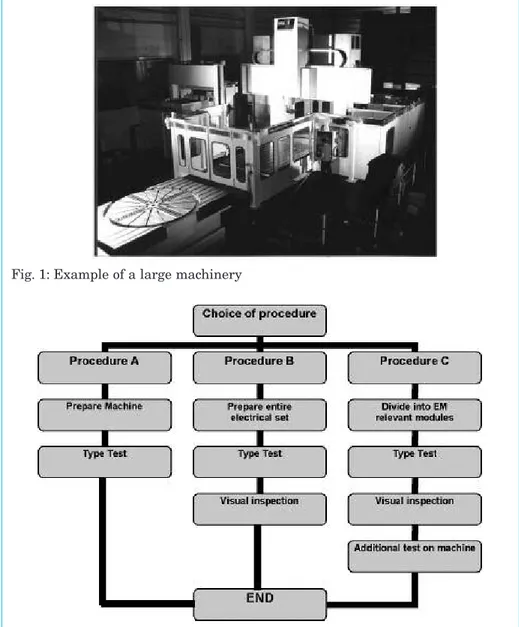
The test approach described in these standards is quite informative. Type testing of a finished product should be the normal method for conformity Fig. 1: Example of a large machinery
assessment. In the case of a complete machine tool or in the case of large machines, a complete testing is only technically and economically feasible for a limited number of machines. It should be well defined what a type-testable machine is considering weight, dimensions, operation, testing costs and testing delay conditions.
The decision for the test procedure is mainly based on the question if the machine contains or not electromagnetic relevant components and/or modules. In the second case, no tests are required. In the first case, three proce-dures are applicable:
– procedure A is a type-test on the com-plete machine,
– procedure B is a type-test on the entire electrical set of the machine, and a visual inspection of the machine regarding the correct installation of the components and cabling,
– procedure C is to divide the machine in EMC relevant modules and test them separately under lab conditions, if not already done, followed by a visual inspection, and a test as final check at the manufacturer premises.
The methodology applies as well for emission, as for immunity EMC requirements, and is given in the flow chart in Table 1.
It is clear that procedure C sounds interesting to the machinery community, also because this allows a flexible way of handling, especially for these machines including a lot of customer based options. It allows an in-depth characterization and validation of all separate modules, and only an addi-tional test is needed on the complete
machine. These final testing may be performed using alternative methods, as developed in the research project TEMCA2.
The TEMCA2 project
This project was conceived and pro-posed by a joint Working Group formed by CECIMO (European Committee for Co-operation of the Machine Tool Industries) and CENELEC. This group prepared also the EN 50370-1/2 stan-dards, dealing with EMC and Machine Tools.
The TEMCA2 project can be seen as a complementary action to these stan-dardisation activities, considering alternative test methods for large machinery. The aim was to develop and evaluate new methods that could not be included in the standards, because of the early stage of development of these alternative methodologies.
Although the scope of the project was regarding large Machine Tools, it is clear that identical methodologies can be used to certify large machinery. The three main objectives of TEMCA2 were:
– development of new methodologies and methods for the evaluation of con-ducted and radiated emission, generated by large machinery, as an alternative to the existing harmonized standards; – development of new methodologies and methods for the evaluation of immunity of large machinery, as an alternative to the existing harmonized standards;
– expertise transfer by means of a
guideline for machine manufacturers.
Conducted emission
The main problem for large machinery is related to two items:
– the current consumption, and the current handling capacity of a LISN; – the fact that it is nearly impossible to insert a measuring probe in the power mains cabling;
– if possible, to develop measuring setups, with a non-contacting probe for the power mains.
Therefore, a number of possible alter-native methodologies have been analysed, and an example of measuring results is given in the next sections.
LISN used as a voltage probe (or LISN in parallel)
In this case, the LISN is only used as a voltage probe, so that the current den-sity is not a restriction on its use. This method is specified in CISPR 16-2-1 [5], and requires the insertion of induc-tances between 30 and 50 µH in the power mains cabling. The only advan-tage of this method with respect to the “classical” use of a LISN is that a low current handling LISN can be used.
Voltage probe 50/1500 Ohm
Referring to both CISPR 16-2-1 [5] and CISPR 11, a voltage probe can be used for measuring the conducted emission levels. This method is not suffering from any restriction about the current density. But it needs a direct contact to the life wires of the power mains, and it introduces an extra attenuation of the
Revue E tijdschrift – 123ste jaargang /123ème année – n° 4-2007 (december/décembre 2007)
18
C.E.M.
signals of about 30 dB, which may cause problems in a noisy environment.
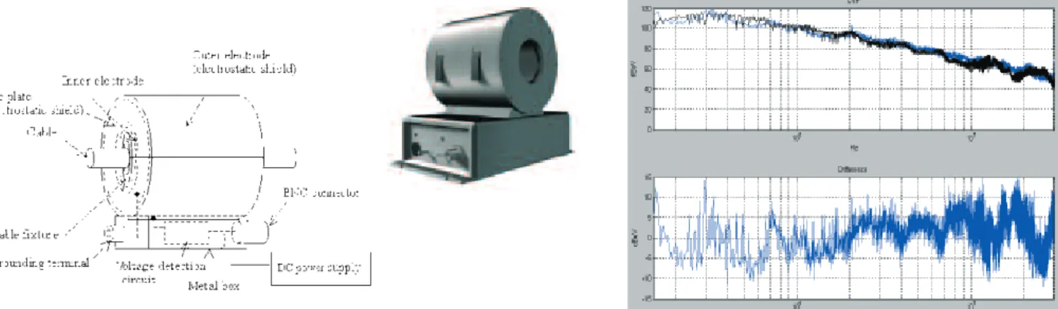
Capacitive Voltage Probe (CVP)
A capacitive voltage probe has been developed, for measuring conducted interference from signal and data com-munication lines. Originally, it has been standardized in CISPR 22, but is now part of the CISPR 16 set. Within TEMCA2, the probe has been evaluated Fig. 3. Voltage probe, and comparison of LISN (black) and voltage probe (blue)
Fig. 4: Capacitive Voltage Probe (CVP) and comparison of LISN (black) and CVP (blue)
Fig. 5: Comparison of LISN (black) and EFT clamp as voltage probe (blue)
for use of measuring the conducted interference at the power mains cabling. The main advantage of the CVP is the non-contacting measuring setup and the
built-in pre-amplifier, giving an overall flat attenuation factor. The CVP is shown in the next Fig. 4, which clearly shows the construction and use of the
probe, and an example of measured results is also given in Fig. 4.
EFT capacitive clamp for conduct-ed emission
The EFT capacitive clamp as described in EN 61000-4-4, is normally used to test the immunity of an equipment against Electrical Fast Transients. The EFT capacitive clamp is rather a large and rigid construction, and cannot be used where no flexible access to the cabling is available. This is a drawback with respect to the CVP (and also the capacitive foil). However, shorter lengths for an EFT clamp could be envisaged for practical use, but making
Revue E tijdschrift – 123ème année /123ste jaargang – n° 4-2007 (décembre/december 2007)
21
E.M.C.
Fig. 7: Calibration of the CFP
Fig. 10: Comparison between the simulated attenuation factors of the LISN and the CFP (lumped and transmission line model) (left), and comparison of LISN (black) and CFP (blue) measuring results (right)
Fig. 11: Antenna measuring setup (left) and test-wire setup (right)
Fig. 12: Picture of the GTO on a test-site and the CONCEPT equivalent for simulations Fig. 9: Parameter extraction details, obtained from CRYPTE, showing 67 pF capacitance
them less sensitive. The main advan-tage is the defined impedance level of 50 Ohm, ensuring a good match with a preamplifier and/or measuring receiver. Unfortunately, the attenuation of the EFT capacitive clamp is rather high, and will normally need a preamplifier which might cause problems in noisy environments.
Capacitive Foil Probe (CFP)
In order to combine all advantages of the discussed alternatives, a very flexible Capacitive Foil Probe (CFP) has been developed. It can be inserted in and around any power mains cabling. A capacitor is made by wrapping a foil (aluminium) around the cabling under test. The foil is connected to a measuring receiver or a preamplifier. A typical length of about 30 cm is used for this foil. A couple of practical examples is shown in the Fig. 6.
To validate this probe, both calibration measurements in the laboratory and simulations have been performed, in
order to identify and define the attenua-tion factor (or correcattenua-tion factor to be applied).
For the simulations, both a lumped capacitor model, and a transmission line model have been used. The labora-tory setup and the resulting attenua-tion factor are given in Fig. 7. Simulation details are shown in Fig. 8. From both, it follows that a short CFP of about 30 cm, rigidly wrapped around a cable, may be estimated to generate a capacitor of 50 up to 70 pF.
The characteristics for the transmis-sion line model of the CFP were obtained by using the parameter extraction software CRYPTE, available in the TEMCA2 project via the partner ONERA (France).
In the Figs 9 and 10, more details are given concerning the parameter extracted values, and the resulting data for the attenuation factor and an example of measurements are given.
It can be concluded that, concerning alternative measuring methodologies for conducted emission of the power mains, different measuring setups can be used, and which all provide fair results, given the fact that an appropriate calibration factor must be applied.
Radiated emission
The main problems for in-situ measure-ments for radiated emission are: – the lack of space to perform adequate measurements using antenna’s; – the background noise in an industrial environment.
Therefore, an alternative methodology has been developed, by putting a simple wire over the machine. This wire acts as an antenna, and is able to capture radiated emissions. The problem is to identify and define a correlation factor (or antenna factor) for this “test-wire” method. The general concept of measu-ring setups using antenna’s and using a “test-wire” is sketched in Fig. 11.
Revue E tijdschrift – 123ème année /123ste jaargang – n° 4-2007 (décembre/december 2007)
23
E.M.C.
Fig. 13: First proposal for an antenna-factor (k-factor), resulting from simulation and measurements
Fig. 14: Set of smaller wiring, carrying currents, and the larger “test-wire” for simulations
In order to understand the underlying phenomena, theoretical models have been developed, as well as a represen-tative test-specimen (GTO or Generic Test Object). This GTO has been send around the partners for a round-robin test, in order to compare classical antenna measurements and the results forthcoming from the test-wire method. In order to have a better understanding of the simulation process, first the GTO will be shortly discussed. The GTO has been designed as a generic machine. This means a type of metal enclosure, with noisy components inside (typically frequency converters) and a lot of cabling coming out for capturing data of external sensors. The noisy content was generated by an appropriate comb-generator, and the external cabling was provided by some wires near the ground and at a larger distance from the ground. The GTO is shown in Fig. 12. Using the simulation software CON-CEPT, both the field strength at 3 m distance and the induced voltage in the test-wire have been calculated. The cal-culated field strength is the reference to be used, when judging the radiated emission levels against the actual stan-dards and the specified limits. An antenna-factor or k-factor for the test-wire is obtained by calculating the ratio between the field strength and the induced voltage in the test-wire. In the next figure, the k-factors obtained from simulations and measurements of the GTO are compared, and a suggestion for practical use is shown.
Another simulation has been per-formed, by introducing a set of “sources”, simulated by wiring carrying
currents, and a larger “receiving” test-wire. This setup is shown in the Fig. 14. A set of 6 cables was placed at 60° interval, each carrying a current gene-rated by the same reference source, but using different load resistances. The induced voltages in the test-wire were recorded. By taking sources at both ends of the generator wires, 6 different situations were obtained. In the next figure, the induced voltages are shown. A first figure shows the influence of each wire/source combination, and the final one shows the average over all 6 combinations.
As a result, different proposals for the “antenna-factor” have been formulated. An on-going evaluation action is
cap-turing data, in order to get a better sta-tistical overview of different types of large machines, and to formulate a final proposal for an adequate antenna-fac-tor. The antenna-factor or k-factor was obtained by calculating the ratio between field strength at 3 m distance (antenna measurement) and the induced voltage in the test-wire. Fig. 16 shows 4 different proposals for this k-factor. From the first CONCEPT simulations of the GTO, a first proposal was made as “-10 to 30 dB at 300 MHz, and than flat”, by curve fitting of the calculated data. During the further evaluation process, based on more sim-ulations and measurements, different proposals were formulated. One of the “corrections” was based on the fact that Fig. 16: Different proposals for antenna-factor, given simulated results cable per cable (left) and all cables (right)
Fig. 17. Example of measurements using antenna method and test-wire method, for GTO in EMC labs
antenna’s, acting as passive circuits, should fit into a “n x 20 dB/decade” slope. In that perspective, the k-factor “– 5 to 15 dB at 300 MHz, constant 15 dB up to 700 MHz, then constant 25 dB” seems to give reasonable results. Different measurement sessions have been performed by the 4 EMC laborato-ries, participating in the TEMCA2 pro-ject. Tests were performed as well as on the GTO, under controlled lab condi-tions, as “in-situ” on large machinery. An example of measuring results is shown in Fig. 17. More details are shown in the next section, especially about the termination of the test-wire in a Common Mode 150 Ohm impedance.
Immunity testing of large
machinery
Concerning immunity testing, distinc-tion must be made between transients and modulated carriers from radio transmitters and the like. During the TEMCA2 project, it was found and shown by evidence that no combined test signal is able to cover both physi-cally different phenomena.
The main reason is that sharp edges of spikes will mostly interfere with logical circuitry, and that demodulated CW carriers (due to non-linear effects of components), will interfere in the pass-band of sensitive small-signal analogue amplifiers of sensors.
In practical situations of large machinery, surge seems not to be an issue, as most machines are not directly connected to the public mains, and appropriate pro-tection devices may be already provided for the machine. This allows visual inspection, checking for the correct application of these devices.
Another point is the restriction on radia-ted immunity, as it is not allowed to transmit RF signals to avoid distur-bances of established radio services. Radiated immunity testing can only be performed at the allowed ISM frequen-cies, where higher power can be used. The alternative is based on the applica-tion of EN 50370-2 standard [4]. In that standard, a test-path “C” is described, by testing separately all appropriated electronic modules and components
Revue E tijdschrift – 123ème année /123ste jaargang – n° 4-2007 (décembre/december 2007)
25
E.M.C.
Fig. 18: Examples of Bulk Current Injection clamps, EM 101 up to 1 GHz (above) and Körber up to 6 GHz (under)
Fig. 19: Comparison of BCI clamp (EM 101), EFT capacitive clamp and CFP probe for conducted immunity tests
Fig. 21: Conducted emission using LISN (left) and CFP probe (right)
Fig. 22: Sketch of the measuring setup for radiated emission using the test-wire method
Fig. 23: Applying the test-wire in practice (left) and its termination in 100/50 Ohm
Fig. 24: Comparison of measured radiated emission by antenna method (left) and test-wire (right)
Fig; 25: Example of comparison between antenna method and test-wire method, and proposed k-factors
under lab conditions, and a final check of the installation practice on the machine.
Another alternative method is to use a Bulk Current Injection (BCI) technique on the wiring and cabling, up to 1 GHz and higher. Research performed by CETIM and KHBO, but out of the TEMCA2 framework, has shown that for typical industrial cabling and wire harnesses, about 1.5 mA is found to be injected to simulate the effect of an impinging field strength of 1 V/m. This relationship can be considered as a worst-case rule of thumb, and more research is actually performed, in order to establish a fine-tuning for this value, which will be frequency-dependant. Alternatives for injection of modulated CW carriers are the use of the EFT clamp and the CFP probe. Fig. 19 shows the power needed (using a 40 dB ampli-fier) to generate 3 V on cabling, accord-ing to EN 61000-4-6. It is clear that all three clamps or probes can be used for applying BCI to cable harnesses. But they can also be used for injecting the EFT pulses.
The main advantage is that the same setup can be used for both conducted emission testing and for immunity testing, even up to an equivalent radiated immunity check up to 1 GHz.
By testing each subpart or module in this way, a very cost effective solution has been found. In more, this method allows during the design and engineering process, to evaluate the susceptibility caused by each (sub)set of cabling. Referring to EN 50370-2 [4], path C, compliance of the machinery may be shown by inspection and restricted testing/monitoring of the machine. Testing only at the allowed ISM fre-quencies is then part of this immunity assessment.
Technically, a remaining open question is about the fact if the test-wire could also be used for “radiated” immunity testing of large machinery.
Example of testing of a
large machine in practice
In this section, an example is given how to apply the methods discussed above
and to perform the tests under practi-cal conditions.
The machine to be tested is an Electrical Discharge Machine (EDM) tool from the company ONA™. The machine uses a wire for spark erosion machining and has been used as a reference machine in the TEMCA2 project.
Fig. 21 shows the measured conducted emission of the machine (ON/OFF) using a LISN as reference (left) and the CFP probe (right). It must be noted that no k-factor or correction factor was applied to the CFP measuring results (see above for a detailed analysis about the attenuation generated by the capacitive foil method).
Concerning radiated emission, Figs 22 to 25 show the setup using 6 positions of the test-wire and the practical layout of the test-wire, as well as the mea-sured results for radiated emission, using an antenna method at 3m dis-tance, and the test-wire method. Again, no k-factor or adapted antenna-factor has been applied to the test-wire mea-suring results (see above for a detailed analysis about the k-factor to be applied when using the test-wire setup).
Conclusions
In this paper, an overview has been given on the work performed and the results obtained during the TEMCA2 research project, on “Alternative EMC testing methods for large machines”. For conducted emission, an “easy to apply” CFP (Capacitive Foil Probe) has been identified, characterized and eva-luated.
For radiated emission, a simple test-wire method has been identified. For immunity testing, it has been found that transients and modulated CW signals must be separately treated, but that module testing up to high frequen-cies is possible using current injection techniques.
Anyway, it is referred to the standards EN 50370-1/2 [3,4] for EMC testing of large machinery, and especially to the “path C” to show evidence of com-pliance, by characterising relevant sub-parts and modules, and by checking the
final implementation in the machine by combined visual inspection and simple testing.
The work reported was obtained during the research project TEMCA2, No. G6RD-CT-2002-00865 for the 5th European Framework Program. The full report can be obtained from johan.catrysse@khbo.be
References
[1] Directive 2004/108/EC of the European Parliament and of the Council of the 15 December 2004 on the approximation of the laws of the Member States relating to electromagnetic compatibility and repea-ling Directive 89/336/EEC.
[2] TEMCA2, “Alternative EMC testing methods for large machines”, No. G6RD-CT-2002-00865 for the 5th European Framework Program, GROWTH, Objective 6.2.1. (Methodologies to support standardisation)
[3] CENELEC, EN 50370-1, EMC – Product family standard for machine tools. Part 1: Emissions, 2005
[4] CENELEC, EN 50370-2, EMC – Product family standard for machine tools. Part 2: Immunity, 2003
[5] CISPR 16-2-1, Specification for Radio Disturbance and Immunity Measuring Apparatus and Methods – Part 2-1: Methods of Measurement of Disturbances and Immunity – Conducted Disturbance Measurements, IEC, Rev. 1.1, 2005
[6] Knockaert J. et al., Comparison of alter-native conducted emission measurement methods using FSV and IELF algo-rithms, Proceedings EMC Europe 2006, Barcelona, pp. 718-722
[7] Final report TEMCA2 (can be obtained from johan.catrysse@khbo.be)
[8] S. Coets, V. Beauvois, J. Catrysse and W. Legros, Accuracy of the measure-ments performed in conducted emissions in case of large systems, Proceedings EMC Zurich 2003
[9] S. Coets, V. Beauvois, J. Catrysse and W. Legros, Comparaison de methods de measures alternatives en emission conduite pour les équipements de puis-sance, CEM 2006, Saint-Malo, 2006 [10] R. de Vré, Application de la directive
CEM 2004/108/EC aux installations fixes, Revue E, 2007
Revue E tijdschrift – 123ème année /123ste jaargang – n° 4-2007 (décembre/december 2007)
27
E.M.C.
FMEC (Flanders Mechatronic Engineering Centre), waar het Laboratorium voor EMC deel van uitmaakt. De onderzoeksdomeinen van de groep situeren zich rond EMC en
électromagnétique (CEM) et d’essais de puis-sance (LEP) dans l’unité de recherche Applied & Computational Electromagnetics (ACE).
Les controverses de l’énergie: Fossile, hydroélectrique, nucléaire, renouvelable
Franco Romerio
Presses Polytechniques et Universitaires Romandes Collection «Le savoir suisse»
140 p. - ISBN : 978-2-88074-590-5
28 septembre 2003, et la nuit blanche devint noire. Le sujet n’a pas fini d’interpeller et voici un ouvrage écrit par un professeur à la faculté des sciences économique et sociales de Genève où il coordonne le Groupe «Economie et politique de l’énergie». Il s’agit donc d’un point de vue suisse. Après un constat de complexité de la matière, l’auteur exa-mine les enjeux économiques, sociaux et environ-nementaux: «La planète pourra-t-elle survivre au développement économique?». Il ne s’agit pas ici de défendre une solution, ou un ensemble de solution, mais bien d’exa-miner les différents aspects de la problématique, en citant avantages et risques ou inconvénients. La sécurité d’approvisionnement, ainsi que la notion de «bouquet énergétique» sont discutés, de même que la politique énergétique de la Suisse. L’ouverture des marchés de l’électricité à la concurrence fait l’objet d’un long chapitre, le statut de la Suisse étant quelque peu différent du reste de l’Europe. Le livre se clôture par un sur-vol des technologies disponibles. En conclusion, un ouvrage intéressant qui livre un regard extérieur, hors Europe, hors milieu ingénieur, sur une problématique fort discutée dans nos cercles. Ce livre est publié dans la collection «Le Savoir Suisse» qui publie de petits ouvrages faisant le point sur des aspects particuliers dans des domaines aussi divers que la politique, la société, l’histoire, l’économie, l’environnement, les sciences et technologies, les arts.
http://www.lesavoirsuisse.ch - http://www.ppur.org
Nouvelles technologies de l’énergie – Volume 1
Sous la direction de Jean-Claude Sabonnadière Editions Hermes – Lavoisier
Traité EGEM : Electronique – Génie Electrique - Microsystèmes 303 p. - ISBN 2-7462-1376-1
http://www.hermes-science.com
Dix-huit auteurs, rassemblés sous la houlette du Prof. Jean-Claude Sabonnadière examinent les technologies les plus récentes en matière d’utilisation de l’énergie provenant de sources dites renouvelables. L’ouvrage est partagé en trois parties: le solaire, l’éolien et l’hydrau-lique et marin. Les technologies nécessaires à l’exploitation de chaque
type de source d’énergie sont étudiées en détail. Les composants, les systèmes, les asservisse-ments requis, le contrôle, l’insertion dans les réseaux électriques sont autant d’aspects étudiés pour chacune des sources envisagées. Les aspects économiques sont également abordés. Ce livre exhaustif est indispensable à toute personne acti-ve dans ce domaine, mais est également un outil pédagogique remarquable pour les étudiants se formant dans la discipline de l’exploitation des sources d’énergie dites renouvelables.