HAL Id: tel-00978956
https://tel.archives-ouvertes.fr/tel-00978956
Submitted on 15 Apr 2014
HAL is a multi-disciplinary open access
archive for the deposit and dissemination of sci-entific research documents, whether they are pub-lished or not. The documents may come from teaching and research institutions in France or abroad, or from public or private research centers.
L’archive ouverte pluridisciplinaire HAL, est destinée au dépôt et à la diffusion de documents scientifiques de niveau recherche, publiés ou non, émanant des établissements d’enseignement et de recherche français ou étrangers, des laboratoires publics ou privés.
Hassan Ali Ahmad
To cite this version:
Hassan Ali Ahmad. Design and Analysis of Distributed Mobility Management in IPv6 Mobile Net-works. Networking and Internet Architecture [cs.NI]. Télécom Bretagne, Université de Rennes 1, 2014. English. �tel-00978956�
N° d’ordre : 2014telb0306
S
Soouusslleesscceeaauuddeell’’UUnniivveerrssiittééEEuurrooppééeennnneeddeeBBrreettaaggnnee
Télécom Bretagne
En accréditation conjointe avec l’Université de Rennes 1
Ecole Doctorale – MATISSE
Design and Analysis of
Distributed Mobility Management
in IPv6 Mobile Networks
Thèse de Doctorat
Mention : Informatique
Présentée par Hassan Ali Ahmad
Département : Réseaux, Sécurité et Multimédia (RSM) Laboratoire : Orange Labs
Directeur de thèse : Xavier Lagrange
Soutenue le 28 Janvier 2014
Jury :
M. César Viho, Professeur, Université de Rennes 1 (Président) M. Thomas Noel, Professeur, Université de Strasbourg (Rapporteur)
Mlle. Lila Boukhatem, Maître de conférences, Université Paris Sud (Rapporteur)
M. Tarik Taleb, Chercheur Senior et Expert en Normalisation, NEC Europe (Examinateur) M. Xavier Lagrange, Professeur, Télécom Bretagne (Directeur de thèse)
Mme. Meryem Ouzzif, Ingénieur de Recherche Senior, Orange Labs (Encadrant) M. Philippe Bertin, Ingénieur de Recherche Senior, Orange Labs (Encadrant)
N° of order: 2014telb0306
U
UnnddeerrtthheesseeaallooffEEuurrooppeeaannUUnniivveerrssiittyyooffBBrriittttaannyy
Télécom Bretagne
In joint accreditation with University of Rennes 1
Doctoral School – MATISSE
Design and Analysis of
Distributed Mobility Management
in IPv6 Mobile Networks
PhD Thesis
in Computer Sciences
Presented by Hassan Ali Ahmad
Department: Networks, Security and Multimedia (RSM) Laboratory: Orange Labs
Thesis advisor: Xavier Lagrange
Defended on January 28, 2014
Thesis committee:
Prof. César Viho, Full Professor, Université de Rennes 1 (President) Prof. Thomas Noel, Full Professor, Université de Strasbourg (Reviewer) Dr. Lila Boukhatem, Associate Professor, Université Paris Sud (Reviewer)
Dr. Tarik Taleb, Senior Researcher & Standards Expert, NEC Europe (Examiner) Prof. Xavier Lagrange, Full Professor, Télécom Bretagne (Thesis advisor)
Dr. Meryem Ouzzif, Senior Research Engineer, Orange Labs (Supervisor) Dr. Philippe Bertin, Senior Research Engineer, Orange Labs (Supervisor)
Acknowledgements
I wish to express my gratitude to a number of people that helped me throughout my three-year journey to achieve my PhD degree.
I am truly grateful to my thesis adviser, Prof. Xavier Lagrange, and to my super-visors, Dr. Meryem Ouzzif and Dr. Philippe Bertin, for all their help and guidance throughout my PhD studies and dissertation. I wish I succeeded to build a close relationship with each of them.
I would like to thank the jury members, Dr. Lila Boukhatem, Prof. Thmoas Noel, Dr. Tarik Taleb, and Prof. Cesar Viho, for reviewing my dissertation and discussing it thoroughly.
I also would like to thank all my colleagues at Orange Labs, where I passed three years with daily interaction with them. I mention Pierrick Seite and Lucian Suciu for their help and for exchanging ideas. I also don’t miss to thank Servane Bonjour who initially proposed the PhD and was my supervisor during my first year.
I also thank my colleagues at Telecom Bretagne.
As I did several collaborations during my PhD, I would like to thank my colleagues from INTECS, Alcatel-Lucent, University Carlos III of Madrid, Intel Corporation, Samsung, and University of Aveiro for all the open discussions and for exchanging ideas.
Last but not least, many thanks to my parents and family, to Azary, and to all my friends especially Hadi, Imad, and Hussein for all their support.
Abstract
Current network architectures, as well as mobility management protocols, are generally deployed in a centralized manner. All the data traffic passes through a single centralized entity, and all the users’ bindings are managed at this entity as well. As the number of mobile users and the volume of their traffic increase, such centralized architectures are expected to encounter scalability issues as well as performance issues. Moreover, these protocols are designed to be always activated, managing all the services and all the traffic in the same way. They do not take into consideration that a given mobile user may not move during the use of a service or that a service may not require mobility functions at all. Such approaches may thus lead to non-optimal routing and large overhead due to tunneling mechanisms.
Recently, mobile network operators are experiencing a rapid increase in mobile data traffic. In order to cope with this, a new trend is to flatten networks architectures and hence IP mobility management protocols need to be adapted for such evolution. Therefore, there is a need to define novel mobility management mechanisms that are both distributed and offered dynamically. They should be distributed in order to avoid any network bottleneck or single point of failure, and to provide better reliability. They should be activated and deactivated dynamically as needed, in order to globally reduce the network resources consumption and to increase the achieved performances.
In order to cope with this context, the thesis concerns designing, analyzing, and evaluating novel IPv6 network architectures and mobility protocols that are distributed and dynamic, and in particular distributed mobility management (DMM). First, we present the different architectures of mobile data networks as well as existing mobility protocols. We then extract the DMM problem statement and present the DMM his-tory, discussing the related work. Before proposing any extension, we categorize the existing mobility schemes into global and local mobility management and carry out a comparative analysis on each category. We then draw out conclusions and perspec-tives, paving the way towards proposing enhancements or even a new scheme. After defining a use-case scenario and identifying our requirements and objectives, we pro-pose a new distributed dynamic mobility management scheme. The propro-posed scheme is mainly based on the mobile IPv6 (MIPv6) protocol, with an optional extension for the joint use with the session initiation protocol (SIP). The proposed scheme operations are detailed in different scenarios. In order to evaluate the proposed scheme, we carry out a qualitative analysis as well as a quantitative analysis in terms of mobility costs, handover, and quality-of-service. After assuring the benefits of the proposed scheme, we study its impacts on other aspects such as security considerations and location management, proposing a solution track for each.
Keywords: Distributed Mobility Management, Dynamic Mobility Management, IPv6, MIPv6, PMIPv6, SIP, Protocol Design, Performance Analysis, Mobile Networks, Network Architecture.
Contents
Abstract
vii
Contents
xii
Glossaries
xiii
Acronyms . . . xiii Symbols . . . xviiiIntroduction
1
I
State of the Art
7
1 Mobile Data Networks and Mobility Protocols 9 1.1 Mobile Data Networks . . . 91.1.1 3GPP mobile networks . . . 9
1.1.2 3GPP2 mobile networks . . . 17
1.1.3 Mobile WiMAX . . . 18
1.2 IPv6 Mobility Protocols . . . 19
1.2.1 Mobile IPv6 (MIPv6) . . . 20
1.2.2 Proxy Mobile IPv6 (PMIPv6) . . . 22
1.2.3 Session Initiation Protocol (SIP) . . . 24
1.3 Distributed Mobility Management . . . 26
1.3.1 Problem statement . . . 26
1.3.2 History of DMM . . . 28
1.3.3 Dynamic Mobility Anchoring (DMA) . . . 29
II
Protocols Modeling and Analysis
33
2 Analysis Models and Criteria 35
2.1 Introduction . . . 35 2.2 Analytical Models . . . 35 2.2.1 Network model . . . 35 2.2.2 Mobility model . . . 37 2.2.3 Refreshing rate . . . 38 2.2.4 Traffic model . . . 40
2.2.5 New traffic vs Handover traffic . . . 42
2.2.6 Delay model . . . 43
2.3 Cost Analysis . . . 44
2.3.1 Signaling cost . . . 44
2.3.2 Data packet delivery cost . . . 45
2.3.3 Tunneling cost . . . 45 2.3.4 Processing cost . . . 46 2.4 Handover Analysis . . . 46 2.4.1 Handover latency . . . 46 2.5 QoS Analysis . . . 47 2.5.1 Packet loss . . . 48 2.5.2 E2E delay . . . 48 2.6 Summary . . . 49
3 Analysis of Global Mobility Management Schemes 51 3.1 Introduction . . . 51
3.2 Mobile IPv6 (MIPv6) . . . 52
3.2.1 Overview on MIPv6 . . . 52
3.2.2 MIPv6 signaling and processing costs . . . 54
3.2.3 MIPv6 data and tunneling costs . . . 55
3.3 Session Initiation Protocol (SIP) . . . 56
3.3.1 Overview on SIP . . . 56
3.3.2 SIP signaling and processing costs . . . 56
3.3.3 SIP data and tunneling costs . . . 57
3.4 Mixed MIPv6-SIP (MMS) . . . 57
3.4.1 Overview on MMS . . . 57
3.4.2 MMS signaling cost . . . 58
3.4.3 MMS data and tunneling costs . . . 59
3.5 Numerical results and discussions . . . 59
3.5.1 Impact of the cell’s radius . . . 60
3.5.2 Impact of the sessions arrival mean rate . . . 62
3.6 Conclusions and Perspectives . . . 65
4 Analysis of Local Mobility Management Schemes 67 4.1 Introduction . . . 67
4.2 Proxy Mobile IPv6 (PMIPv6) . . . 68
Contents xi
4.2.2 PMIPv6 signaling and processing costs . . . 69
4.2.3 PMIPv6 data and tunneling costs . . . 70
4.3 Dynamic Mobility Anchoring (DMA) . . . 70
4.3.1 Overview on DMA . . . 70
4.3.2 DMA signaling and processing costs . . . 72
4.3.3 DMA data and tunneling costs . . . 73
4.4 Numerical results and discussions . . . 74
4.4.1 Impact of the sessions arrival mean rate . . . 74
4.4.2 Impact of the cell’s radius . . . 77
4.4.3 Impact of the network scale . . . 79
4.5 Conclusions and Perspectives . . . 81
III
Protocol Design and Evaluation
83
5 Distributed Dynamic Mobility Management 85 5.1 Introduction . . . 855.2 Preliminaries . . . 86
5.2.1 Use-case scenario . . . 86
5.2.2 Approach roots . . . 87
5.2.3 Requirements & Objectives . . . 87
5.3 Distributed Dynamic MIPv6 (DDM) . . . 88
5.3.1 Recall on MIPv6 . . . 88
5.3.2 DDM concepts . . . 89
5.3.3 DDM different scenarios . . . 89
5.4 DDM Protocol Operation . . . 91
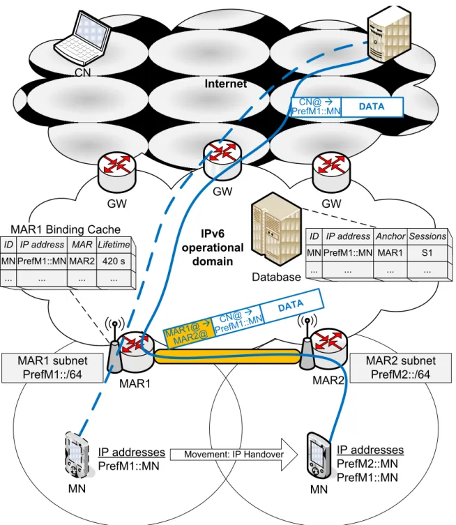
5.4.1 Detailed example on DDM operation . . . 91
5.4.2 Anchors/sessions database in DDM . . . 94
5.4.3 Global mobility support in DDM . . . 95
5.5 Joint DDM–SIP (JDS) . . . 97
5.5.1 Concept of joint DDM–SIP . . . 97
5.5.2 Source address selection . . . 98
5.6 Conclusion . . . 99
6 Qualitative and Quantitative Analyses 101 6.1 Introduction . . . 101 6.2 Qualitative Analysis . . . 102 6.2.1 Overview . . . 102 6.2.2 DDM vs MIPv6 . . . 102 6.2.3 DDM vs DMA . . . 104 6.3 Cost Analysis . . . 105 6.3.1 DDM mobility costs . . . 105 6.3.2 JDS mobility costs . . . 106
6.3.3 Parameters’ default values . . . 107
6.3.4 Impact of the sessions arrival mean rate . . . 108
6.3.6 Impact of network scale . . . 112
6.3.7 Impact of HA to AR deployment ratio . . . 114
6.4 Handover Analysis . . . 115
6.4.1 Handover latency . . . 115
6.4.2 Impact of wireless-link failure probability . . . 116
6.4.3 Impact of network scale . . . 117
6.5 QoS Analysis . . . 118
6.5.1 Packet loss . . . 118
6.5.2 Impact of sessions arrival mean rate . . . 118
6.5.3 End-to-End Delay . . . 119
6.5.4 Impact of wireless-link failure probability . . . 120
6.5.5 Impact of network scale . . . 120
6.6 Conclusions . . . 122
7 Complementary Studies 123 7.1 Security Considerations . . . 123
7.1.1 Introduction . . . 123
7.1.2 Threats, attackers and attacks . . . 124
7.1.3 Link-layer Security . . . 124 7.1.4 Bindings-related Security . . . 126 7.2 Location Management . . . 129 7.2.1 Introduction . . . 129 7.2.2 MIPv6-based Reachability . . . 129 7.2.3 SIP-based Reachability . . . 130
7.2.4 Location Areas Concept . . . 131
7.2.5 SIP with Location Areas . . . 131
7.2.6 Location updates load on SIP Registrar Server . . . 134
7.2.7 Numerical Results . . . 134
7.3 Summary . . . 138
Conclusions and Perspectives
139
Appendix: Résumé en Français
145
List of Publications
151
Glossaries
Acronyms
2G 2nd generation telecommunications system
3G 3rd generation telecommunications system
3GPP 3rd generation partnership project 3GPP2 3rd generation partnership project 2
4G 4th generation telecommunications system
A
AAA authentication, authorization, and accounting
ACK acknowledgement
AH authentication header
AP access point
AR access router
ASN access service network
ASN-GW ASN gateway
ASP access service provider
B
BA binding acknowledgement
BS base station
BSC base station controller
BT bidirectional tunneling
BTS base transceiver station
BU binding update
C
CA certificate authority
CDG CDMA development group
CDMA code division multiple access
CDN content delivery network
CN correspondent node
CoA care-of address
CoT care-of test
CoTI care-of test init
CPA certificate path advertisement
CPS certificate path solicitation
CSN connectivity service network
D
DA destination address
DAD duplicate address detection
DB database
DDM distributed dynamic MIPv6
DHCP dynamic host configuration protocol
DMA dynamic mobility anchoring
DMM distributed mobility management
DNS domain name system
DoS denial of service
E
EAP extensible authentication protocol
eNodeB evolved Node B
EPC evolved packet core
EPS evolved packet system
ESP encapsulating security payload
E-UTRAN evolved UMTS terrestrial radio access network F
FQDN fully qualified domain name
G
GGSN gateway GPRS support node
GPRS general packet radio service
GSM global system for mobile communications
GSMA GSM Association
GTP GPRS tunneling protocol
GTP-C GTP control plane
GTP-U GTP user plane
GW gateway
H
HA home agent
HLR home location registrar
HNP home network prefix
HoA home address
Glossaries xv
HoTI home test init
HSPA high speed packet access
HSS home subscriber server
HTTP hyper text transfer protocol
I
IEEE institute of electrical and electronics engineers IETF internet engineering taskfoce
IKEv2 internet key exchange version 2
IMS IP multimedia subsystem
IP internet protocol
IPsec internet protocol security
IPTV IP television
IPv6 internet protocol version 6
IQ info query IR info reply J JDS joint DDM-SIP L L2 layer 2 L3 layer 3 LA location area
LMA local mobility anchor
LTE long term evolution
M
MAG mobile access gateway
MAR mobility-capable access router
MEXT mobility extensions for IPv6
MIPv6 mobile IPv6
MITM man-in-the-middle
MME mobility management entity
MMS mixed MIPv6-SIP
MN mobile node
MS mobile station
N
NDP neighbor discovery protocol
NEMO network mobility protocol
NETEXT network-based mobility extensions
NETLMM network-based localized mobility management
NodeB UMTS base station
P
PBA proxy binding acknowledgement
PBU proxy binding update
PCF packet control function
PDN packet data network
PDSN packet data serving node
PGW packet data network gateway
PKI public key infrastructure
PMIPv6 proxy mobile IPv6
PPP point-to-point protocol
Q
QoS quality-of-service
R
RA router advertisement
RADIUS remote authentication dial in user service
RAN radio access network
RD router discovery
RFC request for comments
RNC radio network controller
RO route optimization
RR return routability
RRC radio resources control
RS registrar server
RSA rivest-shamir-adleman
S
SA security association
SA source address
SAE system architecture evolution
SAS source address selection
SDN software defined networking
SEND secure neighbor discovery
SGSN serving GPRS support node
SGW serving gateway
SIP session initiation protocol
SLAAC stateless auto address configuration
SMS short message service
SMTP simple mail transfer protocol
SPD security policy database
T
TCP transmission control protocol
TEID tunnel endpoint identifier
Glossaries xvii
TS technical specification
TV television
U
UDP user datagram protocol
UE user equipment
UMTS universal mobile telecommunications system
URI uniform resource identifier
UTRAN UMTS terrestrial radio access network V
VoIP voice over IP
W
WG working group
Wi-Fi wireless fidelity
WiMAX worldwide interoperability for microwave access
Symbols
δ IPv6 data packet size
ηa refreshing mean rate during LA-residence time ηbu
a ηa for the BU procedure
ηregister
a ηa for the REGISTER procedure
ηc refreshing mean rate during cell-residence time ηbu
c ηc for the BU procedure
ηregister
c ηc for the REGISTER procedure
θ IPv6 type 2 routing header size
λh handover traffic arrival mean rate
λn new traffic arrival mean rate
λs sessions arrival mean rate (to a mobile node)
µa LA-crossing mean rate
µc cell-crossing/handover mean rate
µs a typical session duration mean rate
ξ network scale (the ratio har,ar/har,central)
τ IPv6-in-IPv6 tunneling overhead size
Aa LA’s area
Ac cell’s area
Bwd bandwidth of a wired-link
Bwl bandwidth of a wireless-link
dwl(p) (general form) delay of a packet of size p sent over a wireless-link dx,y(p) (general form) delay of a packet of size p sent between x and y
DC data packet delivery cost
har,ar average number of hops between two ARs in the same domain har,central average number of hops between an AR and a centralized entity har,home average number of hops between an AR and the home network hinternet average number of hops through the Internet
hwl weighted wireless-link hop (between MN and AR)
hx,y (general form) average number of wired hops between x and y
Glossaries xix
Lc cell’s perimeter
Lwd propagation latency over a wired-link Lwl propagation latency over a wireless-link
LU location update
Mx (general form) message x size
N number of cells in network operational domain
Nanchor average number of anchors for an MN at a time
Ncn average number of CNs for an MN at a time
Np/s average number of packets per session NP L packet loss (number of lost packets)
Nr number of refreshing during cell-residence time Psip
cn the probability that the CN’s session is SIP-supported Pf probability that the wireless-link fails
Ph probability that a traffic is a handover traffic Pn probability that a traffic is a new traffic
P C processing cost
R cell’s radius
Rro (in MIPv6) the ratio between the number of packets sent in the RO mode and the total number of packets sent during the session
SC signaling cost
tc cell-residence time (random variable)
Tbu lifetime period of the BU message
TE2E end-to-end delay
THL handover latency
TL2 Layer 2 (L2) handover latency
TLU location update latency
TM D movement detection latency
Tregister lifetime period of the REGISTER message
T C tunneling cost
Introduction
Recently, mobile network operators are experiencing a rapid increase in mobile data traffic. Operators’ statistics show that 2012 has seen more mobile data traffic than all the preceding years combined [1]. Between 2012 and 2013, they show that the voice traffic has increased only two percent but the data traffic has doubled on mobile net-works [1,2,3, 4]. Nowadays, high-speed mobile data networks, such as 4G, are widely deployed all around the world. Mobile users can enjoy high data rate transmission. This stimulates the usage of smart phones and thus generates a dramatic increase of the load on mobile networks. A typical mobile PC is expected to generate 11GB, a tablet 3.1GB, and a smartphone around 2GB per month by the end of 2018 [4]. Not only the data traffic of current users is increasing, but also the number of subscriptions and users [1, 2,3, 4].
As a result, mobile network operators are expecting an explosion in mobile data traffic [1, 4, 5]. They are therefore performing various efforts to tackle such challenge, especially at the standardization organizations. Several new technologies and practices are showing up as hot topics. Fixed-mobile network convergence, mobile data offload-ing, decentralized network architecture, software-defined networks, cloud computoffload-ing, and many others are ongoing attempts to cope with the challenge of the new era of mobile data networks.
However, the presented challenge stems from the fact that current mobile network architectures are deployed in a hierarchical and centralized manner. Due to backhaul-ing of all data traffic, a centralized gateway experiences high demands, high bandwidth requirements, and also high processing loads. This is resulting in undesirable network bottleneck and single point of failure. This is also resulting in long communication paths between users and servers, which wastes network resources and leads to unde-sirable delays. Therefore, the mobile network operators’ new trend is to flatten the network architecture.
An essential function in mobile data networks is the mobility management. It relies on mobility protocols in order to provide session-continuity as well as reachability for mobile users. The users can enjoy non-interrupted Internet communications while moving around. The existing mobility protocols have been designed for the current network architectures, relying on a centralized entity. As network architectures are evolving and being flattened, mobility protocols need to be adapted and extended for such evolution.
In this context, the telecommunications operator Orange [6] initiated in 2008 sev-eral projects that consider distributed mobility management (DMM). Orange efforts resulted in a proposal called dynamic mobility anchoring (DMA) [7, 8, 9]. DMA was not based on the IETF [10] mobility protocols.
In 2010, Orange and others pushed the topic to the IETF for discussion. The topic gained interest from various telecommunications industry and academic institutes. At IETF, it was required to extend the IETF mobility protocols, such as mobile IPv6 (MIPv6) [11] or proxy mobile IPv6 (PMIPv6) [12], rather than to propose a new one. Therefore, Orange attempted [13,14] to adapt DMA to appear as an extension of one of the IETF mobility protocols, the PMIPv6 protocol.
However, the desire to design a DMM protocol that is based on existing mobility protocols was not satisfied. For this reason, Orange Labs in collaboration with Telecom Bretagne proposed at that time in October 2010 this PhD thesis to achieve this goal. This PhD was carried out in Orange Labs under an industrial contract for research (called CIFRE).
Beside contributing to the Orange internal project LETSMOVE, I contributed through this PhD to the European projects MEVICO [15] and CROWD [16] (and their deliverables), to the IETF standardization (DMM working group), as well as to several industrial and academic collaborations such as with Intel Corporation, Samsung, and University of Aveiro. In addition, I published several International publications and submitted a patent application.
In short, this PhD thesis concerns designing, analyzing, and evaluating novel net-work architectures and mobility protocols that are both distributed and dynamic.
The thesis is divided into three parts as follows.
Part I
In Chapter1, we review carefully the different architectures of the existing mobile data networks, including the 3GPP [17] (from the general packet radio service (GPRS) to the evolved packet system (EPS)), 3GPP2 [18] and mobile WiMAX [19] architectures. We also go over the current practices of the existing IP mobility protocols, namely mobile IPv6 (MIPv6) and proxy mobile IPv6 (PMIPv6). In general, these architectures and protocols are deployed in a hierarchical and centralized manner. Moreover, they are designed to be always activated, regardless of the mobility and service contexts. Besides, we consider mobility support at upper layers through the session initiation protocol (SIP) [20,21] since it performs in a very different manner, that is end-to-end. Throughout all of these reviews, we extract the distributed dynamic mobility man-agement (DMM) problem statement. Instead of being centralized, mobility manage-ment should be distributed in order to avoid any network bottleneck or single point of failure. Instead of being always-activated, mobility management should be dynami-cally activated and deactivated in order to reduce network resources consumption and
Introduction 3
to achieve better performance. As DMM is addressed at the the IETF (since 2010, when this thesis started) and then chartered as a working group, we present its history there. We also present and discuss the advantages and shortages of the most relevant work to our study, that is the dynamic mobility anchoring (DMA) scheme. DMA is a mobility management scheme that is, to an extent, based on PMIPv6 but relies on a distributed architecture.
The main contributions of this chapter are twofold. The first is to review thoroughly of the existing network architectures and mobility protocols. The second is to extract the DMM problem statement.
Part II
Since it is required to extend the existing mobility schemes, we aim in this part at investigating thoroughly the strong and weak points of each scheme. We consider this as an essential step before proposing any extension. In order to achieve this, we define an analysis framework, we categorize the schemes, and then we carry out a comparative analysis for each category. This part is partially published in [P1, P4, P6].
In Chapter2, we develop an analytical framework for protocols modeling and anal-ysis. In addition, we define a variety of analysis criteria that can examine thoroughly the mobility protocols. We define the cost analysis metrics in order to analyze the network resources consumption. We also define the handover and quality-of-service analysis metrics in order to examine both control and data planes performances.
Compared to the related studies in the literature, the main contributions are the following. The first is to develop analytically all the protocol aspects (e.g. refreshing rate) as well as the DMM-related aspects (e.g. new vs. handover traffic) that are not addressed before. The second is to define various analysis criteria that can investigate any mobility protocol aspects from several points of view. The third is to develop for each analysis metric a general analytical expression that can be applied to any mobility protocol.
At this stage, we consider the cost analysis as the priority since our main concern is the increase in mobile data traffic. We carry out two comparative cost analyses as follows.
• In Chapter 3, we consider the global mobility management schemes (i.e. can support global mobility all over the IPv6 Internet) MIPv6, SIP, and also their integration that is called mixed MIPv6-SIP (MMS).
• In Chapter4, we consider the local mobility management schemes (i.e. can support local mobility within a single operational domain) PMIPv6 and DMA.
After detailing the operations, procedures, and signaling exchanges, we develop for each scheme the analytical models of the mobility costs. We then investigate the impact of different parameters on them.
The main contributions of these two analyses are the conclusions and perspectives that we draw out after each analysis. Through these conclusions, we pave the way to-wards proposing enhancements or even a novel scheme. For instance, we demonstrate the benefits of the joint use of IP mobility and SIP. We also mention the interest in considering scenarios where the other communicating user is mobility-unaware. More-over, we examine the expected advantages of distributed architectures, on both control and data planes aspects.
Part III
After investigating the existing mobility schemes, we conclude their shortages and propose a novel one. We then analyze its performance and study its impacts on other networking aspects. Through some of the results of this part, we have contributed to [P2, P3,P5, P7, P8, P9, D1, D2, I1, I2].
In Chapter5, we propose a novel distributed dynamic mobility management scheme. The proposed scheme is mainly based on the MIPv6 protocol, called distributed dy-namic MIPv6 (DDM), with an optional extension for the joint use with SIP, called joint DDM-SIP (JDS).
After illustrating a use-case scenario, we define our requirements and objectives, considering the conclusions of all the previous analyses. Based on the requirements, we define the two concepts of the proposed scheme: distributed mobility management and dynamic mobility management. The former can be achieved by confining the mobility support and distributing the mobility anchoring functions at the access routers level, keeping the rest of the network unaware of the mobility events and their support. The latter can be accomplished by activating the IP mobility support only when needed, i.e., when both the mobile user actually undergoes an IP handover and the applicative service needs the mobility support as well.
In addition to proposing a new mobility scheme, the main contributions are the following. i) DDM supports both local and global mobility scenarios. The mobile user can move not only within its operational domain but also between different operational domains and access networks. This gains interest as the future wireless and mobile Internet is expected to be composed of several access networks. ii) Moreover, DDM considers both scenarios of full and partial deployment of the mobility functions at the access routers. The mobile network operator may opt to deploy the mobility functions either at each access router or at some of them only. This feature allows a trade-off between the targeted performance and deployment monetary cost. It also eases the architecture migration phase, allowing a step-by-step migration. iii) Besides, we introduce the optional joint use of DDM and SIP, JDS. In JDS, SIP supports mobility for the SIP-based sessions and DDM for the other sessions. The motivation behind such joint use is to reduce further the overhead and achieve better performance if possible, noting that SIP is an end-to-end protocol that does not rely on anchoring or tunneling mechanisms.
Introduction 5
After proposing a new scheme, it is essential to analyze and evaluate it in comparison with other protocols and proposals. It is also essential to study its impacts on other networking aspects.
In Chapter6, we carry out a qualitative analysis and a quantitative analysis. Beside DDM, we consider DMA, MIPv6, PMIPv6, and SIP. The qualitative analysis studies the main characteristics and impacts of the different schemes. It also discusses the main benefits of DDM versus the main relevant schemes, MIPv6 and DMA. The quantitative analysis includes a cost analysis, a handover analysis, and a quality-of-service analysis. We investigate the impact of many parameters on the different analyses metrics. As a result, all the performance evaluations encourage towards adapting the proposed scheme. We show that DDM reduces significantly the mobility costs and hence the network resources consumption. We also show that DDM reduces significantly the handover latency and end-to-end delay, providing better performance and quality-of-service to the end user.
In Chapter7, we present two complementary studies that are accomplished in order to complete and perfect the proposed scheme. The first concerns the security consid-erations. We study both the link-layer and binding-related security aspects. We then propose the use of some existing protocols and mechanisms to overcome the identified issues. The second concerns the location management for reachability support. We study the possibility of reachability support at the IP layer through MIPv6 as well as at the application layer through SIP. We then introduce the concept of location areas to SIP in order to reduce the location updates loads at the SIP servers. We compare, through performance analysis, those loads between the default mode of SIP and the proposed one.
Part I
CHAPTER
1
Mobile Data Networks
and Mobility Protocols
In this chapter, we present the different mobile data networks architectures as well as the different mobility protocols. Through the evolution of these architectures, we then introduce the need for distributed mobility management (DMM). We present the DMM problem statement, its history and current status at the Internet engineering task force (IETF) [10], as well as the related work.
1.1
Mobile Data Networks
After being designed for voice communications, mobile networks are nowadays utilized more for data services. Although voice is still one of the crucial services from users’ standpoint, it is seen as one of the plenty data services from the perspective of mobile network operators. Voice traffic is even foreseen to form a small percentage of total traffic and to consume network resource much less than e.g. video traffic. It is hence the mobile data era and mobile network operators are concerned more and more about the mobile data traffic.
In this section, we present an overview of mobile data networks, including the 3rd generation partnership project (3GPP) [17], the 3rd generation partnership project 2 (3GPP2) [18], and the worldwide interoperability for microwave access (WiMAX) [19] mobile networks, as well as their evolution from an architecture point of view.
1.1.1
3GPP mobile networks
Architecture evolution
After the initial design of global system for mobile communications (GSM, also called 2G) as a circuit-switched network in early 1990s, packet-switched extensions started to appear in late 1990s. The general packet radio service (GPRS, also called 2.5G) enhanced GSM by enabling mobile users to access the Internet. Afterwards, in early 2000s , the universal mobile telecommunications system (UMTS, also called 3G) inher-ited the GPRS architecture and combined the properties of the circuit-switched voice network and the packet-switched data network, offering more possibilities compared to
its predecessors. Then, the high speed packet access (HSPA, also called 3G+) extended UMTS, improving its performance. Later, with the unprecedented interest in mobile Internet, the evolved packet system (EPS) showed up, providing a pure packet-switched and all-IP network.
Although there are much more features to compare between these different systems, we are interested in discussing the evolution in their architectures. We focus then on EPS since it is the most recent system and its deployment is ongoing.
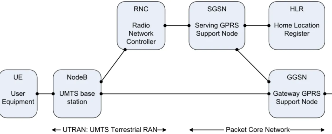
Fig. 1.1, Fig. 1.2, and Fig. 1.3 illustrate the GPRS, UMTS, and EPS networks ar-chitectures [22], respectively. The architectures of GPRS and UMTS are very similar to the extent that they are sometimes referred to as 2G-GPRS and 3G-GPRS, respec-tively. Their radio access network (RAN) is composed of two types of entities that act as base station and controller. Their packet core network is composed of three types of entities, the serving GPRS support node (SGSN), the gateway GPRS support node (GGSN), and the home location registrar (HLR).
Both SGSN and GGSN perform both data plane and control plane duties. The SGSN is responsible for authentication, authorization, and mobility management sig-naling. It is also responsible for data packets forwarding, being the first entity to see the IP data packets in the uplink and the last one in the downlink. The GGSN han-dles session initiation, handover, and session tear-down signaling from the SGSN. It is the topological anchor point of the mobility management, i.e. the topological point of attachment of the user’s IP prefix that is stable while moving. It is the gateway that is responsible for the routing from and to the external IP-networks such as the Internet. On the other hand, the EPS [23, 24, 25] introduces several modifications compared to GPRS and UMTS. It turns the network to all-IP, reduces the hierarchy levels, and separates the data and control planes to a certain extent. Hereafter we describe the EPS architecture in more details.
Evolved Packet System (EPS)
The access network in EPS is called evolved universal terrestrial radio access network (E-UTRAN) [23]. It is also referred to as long term evolution (LTE) access network. It is composed of a unique type of entities, namely the evolved node B (eNodeB). The eNodeB is the base station that offers the radio connectivity.
On the other hand, the core network in EPS is called evolved packet core (EPC) [24]. The EPC supports not only the LTE access network but also other types of 3GPP and non-3GPP access networks. The EPC is composed of four types of entities as follows.
• serving gateway (SGW);
• packet data network gateway (PGW); • mobility management entity (MME); • home subscriber server (HSS).
1.1. Mobile Data Networks 11 BTS Base Transceiver Station BSC Base Station Controller MS Mobile Station GGSN Gateway GPRS Support Node SGSN Serving GPRS Support Node
RAN: Radio Access Network Packet Core Network HLR Home Location
Register
Figure 1.1: GPRS network architecture.
NodeB UMTS base station RNC Radio Network Controller UE User Equipment GGSN Gateway GPRS Support Node HLR Home Location Register SGSN Serving GPRS Support Node
UTRAN: UMTS Terrestrial RAN Packet Core Network Figure 1.2: UMTS and HSPA Release 6 network architecture.
eNodeB evolved NodeB UE User Equipment PGW Packet Data Network Gateway MME Mobility Management Entity SGW Serving Gateway HSS Home Subscriber Server
E-UTRAN Evolved Packet Core
The gateways (SGW and PGW) deal with the data plane. They transport the IP data traffic between the user, referred to as user equipment (UE) in EPS, and the external networks.
The SGW is the point of interconnection between the LTE radio-side and the EPC. As its name indicates, this gateway serves the user by routing the incoming and out-going IP packets. It is logically connected to the other gateway, the PGW.
The PGW is the point of interconnection between the EPC and the external IP networks. These networks are called packet data networks (PDN), such as the Internet and the IP multimedia subsystem (IMS) [26]. The PGW routes packets to and from the packet data networks. The PGW also performs various functions such as IP ad-dress/prefix allocation or policy control and charging.
The MME deals with the control plane. It handles the signaling related to mobility and security for E-UTRAN access. The MME is responsible for the tracking and the paging of the user in idle mode.
The HSS is a database that contains user-related and subscriber-related information. Mobility management in 3GPP networks
Basically, 3GPP mobile networks rely on the GPRS tunneling protocol (GTP) [27, 28,
29] for mobility management. EPS allows also the partial usage of proxy mobile IPv6 (PMIPv6) beside GTP [24, 25]. PMIPv6 is described and discussed in Section 1.2.
As its name sounds, GTP is a tunneling protocol that allows the transportation of different networking protocols over the 3GPP core network. Its basic functionality is to uniquely identify the tunnel to which the user IP packets belong. It carries the user IP packets and manages the data plane. It also carries specific signaling traffic between various network entities.
GTP is sometimes considered as a group of communications protocols since it can be decomposed into GTP control plane (GTP-C) and GTP user/data plane (GTP-U) as follows. GTP-C is in charge of creating, modifying (such as adjusting quality of service parameters), and deleting tunnels for the user sessions. It also permits to handle user mobility within the access network. GTP-U encapsulates the user IP packets when passing from the radio access network to the core network and also through the core network.
As GTP establishes different tunnels between the network entities, each tunnel is identified by a tunnel endpoint identifier (TEID). Based on TEID, the network is able to choose the appropriate GTP tunnels to transfer the IP packets between the user and the packet data networks.
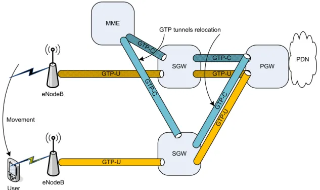
Fig. 1.4 shows the GTP tunnels in EPS network architecture. GTP-C tunnels are used on the PGW–SGW and SGW–MME interfaces. GTP-U tunnels are used on the PGW–SGW and SGW–eNodeB interfaces.∗
∗PMIPv6 can replace GTP on the PGW–SGW interface but neither on the SGW–MME interface
1.1. Mobile Data Networks 13 MME PGW SGW PDN User eNodeB GTP-U GTP-C GTP-C GTP-U
Figure 1.4: GTP tunnels in EPS.
MME PGW SGW PDN eNodeB GTP-U GTP-C GTP-C GTP-U eNodeB GT P-U User GTP tunnel relocation Movement
Figure 1.5: Intra-SGW intra-MME handover in EPS.
When the user moves from one eNodeB to another eNodeB, it may stay in the scope of the same SGW and MME, same MME but different SGW, same SGW but different MME, or different SGW and MME. Depending on the mobility scenario, the relocation of one or more GTP tunnels is needed.
Fig. 1.5 and Fig. 1.6 shows two examples on the intra-SGW intra-MME and inter-SGW intra-MME handover scenarios, respectively. In the first, only the GTP-U tunnel on SGW–eNodeB is relocated since the user is still in the scope of the same SGW and MME. This mobility is transparent to the PGW. In the second, all the GTP-U and GTP-C tunnels are relocated since the user changes the SGW. The old SGW–eNodeB GTP-U tunnel is torn down and a new one is established between the new SGW and new eNodeB of the user. The new SGW is selected by the MME. It is worth mentioning that during the handover, packet forwarding from the previous eNodeB to the new eNodeB may be done directly or through the SGW(s).
Note that GTP mobility management is a network-based approach. When the user undergoes a handover, GTP tunnel(s) relocation between the network entities is
SGW MME PGW SGW PDN eNodeB GTP-U GTP-C GTP-C GTP-U User GTP tunnels relocation Movement eNodeB GTP-U GT P-U GT P-C G TP -C
Figure 1.6: Inter-SGW intra-MME handover in EPS.
handled by the network. The user does not participate in the mobility-related signaling. GTP tunnels can be established only between the 3GPP network entities. GTP mobility management is restricted to the 3GPP domain, i.e. when the user is in the scope of 3GPP networks such as intra-EPS mobility and inter-3GPP mobility.
Mobility management hierarchy in 3GPP networks
As it appears from the two handover scenarios described above, when the user move far enough from the initial point of attachment, the handover has to be performed between higher level network entities. The only network entity that does not change during a session is the network anchor point, i.e. the GGSN in GPRS/UMTS/HSPA and the PGW in EPS. These levels of mobility management create a hierarchy. This hierarchy appears also in the number of network entities in a deployed network.
Fig. 1.7 illustrates the mobility management hierarchy in 3GPP networks architec-tures. The levels of hierarchy are depicted from top to bottom, where the anchor point is at the top and the base stations are at the bottom. The user would be in the bottom of the view moving horizontally.
Therefore, the 3GPP standardization organization attempted to reduce the levels of hierarchy in 3GPP architectures. For instance, HSPA Release 7 introduces new options in order to reduce the levels of hierarchy [30,31]. The first is to bypass the SGSN in the data plane and to establish direct tunnel between the radio network controller (RNC) and GGSN. In the second, the RNC can be bypassed also in order to establish direct tunnel between the NodeB and GGSN. Fig. 1.8 and Fig. 1.9 illustrate these options.
1.1. Mobile Data Networks 15
In EPS, the SGW and the PGW are specified independently but in practice they may be combined in a single entity [24] by network vendors. This entity is then referred to as the system architecture evolution (SAE) gateway (SAE-GW). In fact, it is the case in ongoing deployments. Fig. 1.10 illustrates this case.
Finally, it is worth mentioning that there are ongoing studies on the deployment of IPv6 in 3GPP mobile networks, particularly in EPS [32, 33, 34]. This encourages towards specifying new IPv6 mobility protocols for 3GPP EPS that are not hierarchical.
SGSN SGSN
GGSN
RNC RNC RNC RNC RNC
HLR
NodeB NodeB NodeB NodeB NodeB NodeB NodeB
(a) UMTS and HSPA Release 6
SGW MME MME SGW
PGW
eNodeB eNodeB eNodeB eNodeB eNodeB
HSS
(b) EPS
NodeB UMTS base station RNC Radio Network Controller UE User Equipment GGSN Gateway GPRS Support Node HLR Home Location Register SGSN Serving GPRS Support Node
UTRAN: UMTS Terrestrial RAN Packet Core Network
Figure 1.8: HSPA network architecture with direct RNC–GGSN tunnel.
NodeB UMTS base station RNC Radio Network Controller UE User Equipment GGSN Gateway GPRS Support Node HLR Home Location Register SGSN Serving GPRS Support Node
UTRAN: UMTS Terrestrial RAN Packet Core Network
Figure 1.9: HSPA network architecture with direct NodeB–GGSN tunnel.
eNodeB evolved NodeB UE User Equipment SGW PGW MME Mobility Management Entity HSS Home Subscriber Server
E-UTRAN Evolved Packet Core
1.1. Mobile Data Networks 17
1.1.2
3GPP2 mobile networks
The 3rd Generation Partnership Project 2 (3GPP2) [18] is a collaboration aimed at developing globally applicable specifications for third generation (3G) mobile systems. In practice, 3GPP2 is the standardization group for CDMA2000 which relies on the code division multiple access (CDMA) technology.
As a general philosophy behind the design of the 3GPP2 architecture, the IETF protocols are employed whenever possible [35]. This is in order to minimize the number of new protocols required and to maximize the utilization of well accepted standards and hence the speed to market. Fig. 1.11illustrates the network architecture of 3GPP2 mobile network architecture [36].
The radio access network (RAN) is composed of two functions, namely the radio resources control (RRC) and the packet control function (PCF). The former is respon-sible for radio resources and the latter for layer 2 connection.
On the other hand, the packet data serving node (PDSN) is responsible for establish-ing, maintainestablish-ing, and terminating the point-to-point protocol (PPP) [37] to the mobile station. The PDSN can be considered as the mobile station’s point of attachment.
For security, the architecture relies on a remote authentication dial in user ser-vice (RADIUS) server which provides authentication, authorization, accounting (AAA) management for the mobile stations.
To support IP mobility, the PDSN is connected, through an IP network, to the home agent (HA). The home agent is defined by the mobile IP (MIP) protocol and serves as the mobility management anchor point (as presented and discussed in Sec-tion 1.2). However, the home agent resides in the home network and this leads to mobility management hierarchy similar to the one described above in 3GPP networks. The CDMA development group (CDG) [38] states that, as of September 2013, there are 313 operators in 118 countries offering CDMA2000 service. It is is mostly used in North America and Asia Pacific. It is not considered as wide as 3GPP networks, though. RAN Radio Access Network MS Mobile Station HA Home Agent PDSN Packet Data Serving Node RADIUS Server IP network
1.1.3
Mobile WiMAX
Mobile WiMAX relies on the IEEE 802.16 standard [39] for the air interface and on the WiMAX forum [19] for the requirements, architecture, and protocols. The WiMAX forum has developed a network reference model to serve as an architecture framework for WiMAX deployments [40]. Fig. 1.12 illustrates the mobile WiMAX network archi-tecture.
The access network in mobile WiMAX is called the access service network (ASN). The ASN is owned by an access service provider (ASP) and is composed of two types of entities. The first is the base station (BS) which provides the air interface for users. It may also have some additional functions such as handover triggering, tunnel establishment, and radio resource management. The second is the ASN gateways (ASN-GW) which typically acts as a layer 2 traffic aggregation point within an ASN. It may also have some additional functions such as establishment and management of mobility tunnel with base stations, intra-ASN location management and paging, and routing to the selected core network.
The core network in mobile WiMAX is called connectivity service network (CSN). The CSN is owned by a network service provider (NSP) and provides IP connectivity and all the IP functions. It provides connectivity to the Internet, other public networks, and corporate networks. It is responsible for IP address management and includes the mobility management anchor point. It supports mobility, roaming, and location man-agement between ASNs, and also supports roaming between different NSPs. In addi-tion, the CSN includes authenticaaddi-tion, authorization and accounting (AAA) server(s) and provides per user policy management of quality-of-service and security.
Mobility management in mobile WiMAX relies on IP mobility protocols such as mobile IP (MIP) and hence the anchor point is the home agent (HA). We do not detail the IP mobility protocols here since we present and discuss them in Section 1.2. How-ever, the anchor point is in the CSN and this leads to mobility management hierarchy similar to the one described above in 3GPP networks.
BS Base Station MS Mobile Station CSN Connectivity Service Network
Radio Access Network Core Network
ASN-GW Access Service Network Gateway CSN Connectivity Service Network
1.2. IPv6 Mobility Protocols 19
Finally, it can be said that mobile WiMAX has been a step towards IP-based mobile networks. Although mobile WiMAX has been deployed in by more than 200 operators in more than 80 countries [41], it is not considered as wide as 3GPP networks.
1.2
IPv6 Mobility Protocols
After presenting the 3GPP, 3GPP2, and WiMAX mobile networks, we present and discuss in this section the IP mobility protocols.
IP mobility refers to the user’s movement, inside a network (local mobility) or between networks (global mobility), that leads to a change in the point of attachment at the IP level. The IP mobility event is referred to as IP handover. The IP mobility leads to a change in the user’s IP address and hence needs to be managed or handled appropriately in order to guarantee the continuity of the user’s ongoing sessions.
The IP mobility protocols refer to the protocols that can manage or handle the IP mobility. The main IP mobility protocols act at the IP layer in order to manage the IP mobility in such a way the user can still use its previous IP address. Consequently, the IP mobility is transparent to the upper layers. Other protocols act at the upper layers, such as the application layer, and handle the IP mobility even that they do not allow the user to use its previous IP address.
Hereafter, we present the following IP mobility protocols. • mobile IPv6 (MIPv6) [11],
• proxy mobile IPv6 (PMIPv6) [12], • session initiation protocol (SIP) [20, 21].
MIPv6 is the main host-based IPv6 mobility protocol and PMIPv6 is the network-based variant of MIPv6. MIPv6 and PMIPv6 are standardized by IETF and considered as the key IPv6 mobility protocols. They are well investigated, tested and deployed. They are included in several 3GPP, 3GPP2, and mobile WiMAX specifications such as [24, 25,36, 40, 42, 43]. It is essential to consider them in our study.
SIP is an application-layer signaling protocol standardized by IETF. It is well in-vestigated with lot of extensions, and deployed in mobile networks. Although IETF does not look at SIP as a mobility protocol, SIP can natively support mobility as well as reachability at the application-layer for Sbased sessions. Compared to IP-layer mobility schemes, SIP performs in a very different manner and hence it is highly interesting to include it in our study.
In this section, it is intended to introduce these protocols and describe them from architectural standpoint only. However, it is not intended to detail e.g. the opera-tions, procedures, and signaling since they are detailed and analyzed in later chapters, particularly in Chapter 3 and Chapter4.
1.2.1
Mobile IPv6 (MIPv6)
Mobile IPv6 (MIPv6) [11] is an IPv6 mobility protocol that provides session continuity and reachablity while moving around in the global IPv6 Internet. In the context of global mobility, it is not feasible to require additional mobility-related capabilities in all the serving access networks. The only entity that is guaranteed to be aware of the mobile node (MN) mobility is the MN itself. Hence, MIPv6 adopts a host-based scheme and the mobile node (MN) participates in the mobility-related signaling.
In MIPv6, each MN is always identified by its home address (HoA), regardless of its current point of attachment to the Internet. While situated away from its home, an MN is also associated with a care-of address (CoA), which provides information about the MN’s current location.
MIPv6 introduces a new network entity called the home agent (HA). The HA main-tains the MN’s binding between the home address and care-of address in the binding cache. This binding is updated by the MN itself, upon each IP handover. The HA is typically implemented at a router in the MN’s home network and serves as the mobility anchor of the MN. While the MN is away from home, the HA intercepts packets on the home link destined to the MN’s home address, encapsulates them, and tunnels them to the MN’s registered care-of address.
The default mode of communication in MIPv6 is called the bidirectional tunneling (BT) mode. IPv6 packets addressed to the MN’s home address are routed to the HA by standard IPv6 routing mechanisms and then tunneled from the HA to the MN. Similarly, IPv6 packets sent by the MN are tunneled to the HA first then routed to their final destination, the correspondent node (CN).
MIPv6 defines also a route optimization (RO) mode to allow direct communication between the MN and the CN. This is achieved through enabling the CN to cache the binding of an MN’s home address with its care-of address. Then, the MN’s care-of address is used by the CN as a destination address in the packets destined for the MN, and by the MN as a source address in the packets destined for the CN. However, the MN and CN are respectively required to use a new home address destination option and a new type 2 routing header that are defined by MIPv6. This introduces additional overhead. Note that the RO mode cannot be activated unless the CN is an MIPv6 client; this brings significant limitations to the usage of RO.
Fig. 1.13 illustrates the architecture and mobility management of MIPv6 in its default mode. The HA is located in the MN’s home network. The MN moves from visited network 1 to visited network 2, undergoing an IP handover. While the MN’s home address is always PrefH::MN, the MN’s care-of address changes from PrefV1::MN to PrefV2::MN. The MN updates its binding at the HA and the HA registers the new care-of address in the binding cache. All IPv6 data packets from and to the MN are routed via the HA through a tunnel between the MN and the HA.
From architecture point of view, it appears clearly that the HA is the MN’s anchor point in both control plane and data plane.
1.2. IPv6 Mobility Protocols 21 Internet AR2 AR1 CN HA CN Movement: IP Handover HoA: PrefH::MN CoA: PrefV1::MN MN HoA: PrefH::MN CoA: PrefV2::MN MN Visited Network 1 PrefV1::/64 Visited Network 2 PrefV2::/64 Home Network PrefH::/64 HA Binding Cache DATA CN@ PrefH::MN HA@ PrefV2::MN DATA CN@ PrefH::MN ID MN HoA PrefH::MN CoA PrefV2::MN Lifetime 420 s ... ... ... ...
1.2.2
Proxy Mobile IPv6 (PMIPv6)
Proxy mobile IPv6 (PMIPv6) [12] is an IPv6 mobility protocol that is based on MIPv6 but designed/optimized for mobility management in a localized domain, called PMIPv6-domain. In other terms, PMIPv6 provides mobility support in a single op-erational domain but not between different opop-erational domains such as in the global Internet. This limitation in the mobility scope allows the network to be operated in such a way it can manage the nodes mobility by itself. In other terms, the general knowledge on the possible points of attachment for the MN (i.e. the access routers of the domain) allows to implement some mobility functions in all of them so that the MN never attaches to a classical access router.
Compared to MIPv6, the main feature in PMIPv6 is to be network-based. This means that the MN is not required to participate in any mobility-related signaling. It is also not required to handle tunnel establishment and management. Instead, the net-work handles the mobility management on behalf of the MN. Accordingly, no additional capabilities (e.g. MIPv6 client) are required at the MN and the mobility management is totally transparent to the MN.
In order to achieve this, PMIPv6 introduces two network entities, namely the mobile access gateway (MAG) and the local mobility anchor (LMA), as follows.
The MAG is a function on an access router (AR) that manages the mobility-related signaling and also establishes the tunnel for an MN attached to it. It is responsible for tracking the MN’s movements to and from it and for signaling the MN’s LMA to update the MN’s binding. It is also responsible for establishing and managing the tunnel for the MN. It can be said that the mobility functions defined in MIPv6 for the MN are moved from the MN to the MAG.
On the other hand, the LMA is the home agent [11] for the MNs in the PMIPv6-domain. It is the entity that manages the MNs bindings states. It is also the gateway to the external networks such as the Internet. The LMA is the topological anchor point for the addresses, particularly the home network prefix(es), assigned to the MNs in the PMIPv6-domain.
Consequently, the IPv6 packets destined for the MNs addresses are naturally routed to the LMA through standard IPv6 routing mechanisms. The LMA encapsulates these packets and tunnel them to the corresponding MAG. The MAG decapsulates them and delivers them to the MN. Similarly, IPv6 packets sent by the MN are encapsulated at the MAG, tunneled to the LMA, and then routed to their final destination.
It is worth mentioning that in PMIPv6, the MN is always advertised the same home network prefix by the MAG with the help of the LMA. Consequently, the MN uses always its home address and does not need any care-of address. This makes the mobility completely transparent to the MN.
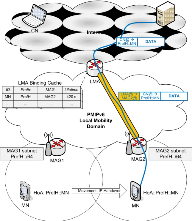
Fig. 1.14 illustrates the architecture and mobility management of PMIPv6. The LMA and multiple MAGs are located in the PMIPv6-domain. The MN moves from one MAG subnet to another MAG subnet, undergoing an IP handover. The new
1.2. IPv6 Mobility Protocols 23
MAG updates the binding at the LMA. The LMA registers the new MAG address in the binding cache entry of the corresponding MN. Then, a bidirectional tunnel is established between the MAG and the LMA for the MN’s data traffic. The figure shows an example how a data packet is sent from the CN to the MN; it is routed to the LMA, tunneled from the LMA to the MAG, and then delivered to the MN.
From architecture point of view, it appears clearly that the LMA is the MN’s anchor point in both control plane and data plane.
Internet PMIPv6 Local Mobility Domain MAG2 MAG1 CN LMA Movement: IP Handover HoA: PrefH::MN MN HoA: PrefH::MN MAG1 subnet PrefH::/64 MAG2 subnet PrefH::/64 LMA Binding Cache
MN CN DATA CN@ PrefH::MN DATA CN@ PrefH::MN LMA@ MAG2@ ID MN Prefix PrefH MAG MAG2 Lifetime 420 s ... ... ... ...
1.2.3
Session Initiation Protocol (SIP)
Session initiation protocol (SIP) [20] is an application-layer signaling protocol for creat-ing, modifycreat-ing, and terminating sessions with one or more participants. These sessions include Internet telephone calls, multimedia distribution, multimedia conferences, and text messaging. SIP supports the following five aspects: user location (to determine the location of a user), user availability, user capabilities, session setup, and session management (e.g. to modify session parameters).
SIP [20] introduces several logical entities to the network. For each domain (e.g. example.com) there is an SIP proxy server and a registrar server (RS). These logical entities are usually co-located when deployed. The proxy servers to help route requests to the user’s current location, authenticate and authorize users for services, implement provider call-routing policies, and provide features to users. Note that the user can obtain the IP address of the SIP proxy server by performing a domain name system (DNS) lookup of the domain name.
SIP identifies each user by a unique SIP uniform resource identifier (URI), e.g. alice@example.com. In order to associate the SIP-URI with the current IP address, SIP provides a registration function that allows the user to upload their current IP address to the registrar server. The registrar writes this association/binding into a database and the user is required to update their IP address upon initial attachment and also upon each IP address change, e.g. when undergoing an IP handover. This information in the registrar server is used by the proxy servers to locate the user when needed, e.g. to forward a request destined for the user. To conclude, it can be said that SIP can natively provide location management and hence reachability support.
In order to initiate a communication in SIP, the caller (e.g. sip:alice@orange.com) is required to invite the callee (e.g. sip:bob@telecomb.com). The invitation includes the caller’s IP address, the callee’s SIP-URI, the session identifier, and other fields. If the caller knows the callee’s IP address, then the invitation can be sent directly. Otherwise, a SIP proxy server can be used to forward the invitation. First, the caller performs a DNS lookup of the callee’s domain name (e.g. telecomb.com) which returns the IP address of the SIP proxy of the callee’s domain (e.g. sip:proxy.telecomb.com). The caller then sends the invitation to this SIP proxy server. The SIP proxy server obtains the callee’s IP address by performing a lookup of the callee’s SIP-URI (which is included in the invitation) at the registrar server. Then, it forwards the invitation to the callee. The callee replies to the caller either accepting or rejecting the invitation.
During the session, any of the communicating users can request to modify the session through re-inviting the other party directly (no need to pass through a proxy this time). Upon undergoing an IP-handover, the user can modify its IP address used to send and receive data packets for the session, without changing the session identifier. Then, the other party updates the session and uses the new IP address as a destination address in the data packets. Consequently, SIP can natively support terminal mobility for SIP-based sessions [21]. Compared to MIPv6/PMIPv6 where the HA/LMA is topologically the anchor point in the data plane, SIP is an end-to-end protocol; data packets are transmitted directly between the communicating users without any tunneling even after
1.2. IPv6 Mobility Protocols 25
undergoing an IP handover. Fig.1.15 illustrates the architecture and mobility support in SIP.
To sum up, although SIP is designed as a signaling protocol, it can natively sup-port both mobility and reachability at application layer for SIP-based sessions. From architecture point of view, SIP is an end-to-end protocol that relies neither on mobility anchoring nor on tunneling mechanisms, and hence it can be said that the data plane is distributed. On the other hand, the control plane relies on the registrar server, the proxy server, and also the DNS, and hence it is kind-of centralized.
Internet AR2 AR1 SIP user Movement: IP Handover IP address PrefV1::MN IP address PrefV2::MN Visited Network 1 PrefV1::/64 Visited Network 2 PrefV2::/64 Home Network
PrefH::/64 Registrar Database
SIP URI alice@orange.com IP address PrefV2::MN Lifetime 3600 s ... ... ... SIP Server (proxy & registrar)
DATA CN@ PrefV2::MN SIP user alice@orange.com alice@orange.com DATA CN@ PrefV1::MN
1.3
Distributed Mobility Management
1.3.1
Problem statement
Current network architectures, as well as IP mobility management protocols, are gen-erally deployed in a centralized manner. All the data traffic passes through a single centralized entity, and all the users’ binding-records are managed at this entity as well. As the number of mobile users and the volume of their traffic increase, such centralized architectures are expected to encounter scalability issues (e.g. network bottleneck, and single point of failure), security issues (e.g. attacks focused on the centralized anchor), as well as performance issues (e.g. centralized and non-optimal routing, large tunneling overhead).
Moreover, these protocols are designed to be always activated, managing all the services and all the traffic in the same way. They do not take into consideration that a given mobile user may not move during the use of a service, which exceeds 60 percent of the cases in operational networks [44] (see Table 1.1), or that a service may not require IP mobility functions at all. Such approaches may thus lead to non-optimal routing and large overhead due to tunneling mechanisms.
Recently, mobile users’ demand on data traffic is increasing dramatically. Operators’ statistics show that the usage of mobile data traffic has doubled during the last year. This is expected to continue in this decade [1, 4, 5] (see Fig. 1.16), especially with the deployment of 4G networks, resulting in an explosion in mobile Internet traffic. In order to cope with such rapid explosion, a new trend is to flatten networks architectures and hence IP mobility management protocols need to be adapted for such evolution.
A flat architecture is by principle composed of a unique functional entity, the access router (AR). The AR is the first-hop router and the user’s point of attachment at the IP level and, for simplicity, at the radio level as well. It provides basic attachment
Table 1.1: Cisco survey on mobile
Internet time at home, at work and on the move [44].
at home at work on the go U.S. 37.8% 19.6% 42.6% U.K. 45.6% 17.8% 36.6% Germany 43.4% 15.3% 41.3% France 33.1% 21.7% 45.2% Italy 39.6% 21.4% 39.0% South Africa 48.6% 21.4% 30.0% Mexico 28.2% 27.6% 44.2% Brazil 36.7% 24.7% 38.6% Korea 33.7% 31.7% 34.6% India 45.9% 30.4% 23.7% China 30.1% 32.7% 37.2% Average 38.4% 24.0% 37.5% 2012 2013 2014 2015 2016 2017 0 2 4 6 8 10 12 0.9 1.6 2.8 4.7 7.4 11.2 Ex ab y tes p er mon th
Figure 1.16: Cisco forecast on mobile data traffic [5].
1.3. Distributed Mobility Management 27
Internet
Operated IPv6 network
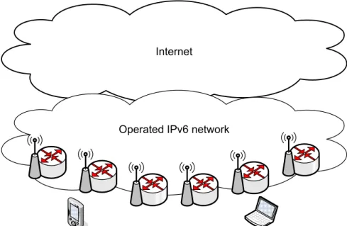
Figure 1.17: IPv6 mobile network with flat architecture.
functions such as IP address allocation and routing. The AR also provides the mobility-related functions and hence these functions are brought to the network edge closer to the user. All the ARs are connected to the Internet through an operated IPv6 network†. Fig.1.17illustrates an example of IPv6 mobile network with a flat architecture (derived by the telecommunications operator Orange).
In conclusion, there is a need to define novel mobility management mechanisms that are both distributed and offered dynamically. They should be distributed in order to avoid any network bottleneck or single point of failure, and to provide better reliability. They should be activated and deactivated dynamically as needed, in order to globally reduce their signaling load and to increase the achieved performances; with the endorsement of the dynamic mobility management the mobility functions are only activated when necessary, depending on the mobility behavior of the user, the type of used services, or the networking context in general.
Accordingly, the IETF chartered recently the distributed mobility management (DMM) working group [45]. Various efforts from both industry and academia are being performed on specifying DMM schemes. One of the DMM requirements [46] is to rely on the existing IP mobility protocols by extending and adapting them. This is in order to benefit such standardized protocols before specifying new ones, and also to facilitate the migration of networks architectures.
The thesis concerns designing, analyzing, and evaluating novel IPv6 network archi-tectures and mobility protocols that are both distributed and dynamic, and in partic-ular Distributed Mobility Management (DMM) architectures and protocols.
†Note that this IPv6-network is under an operator control, which means that the operator can
exceptionally use some control gateways if it is more suitable to keep some control functions separated from the ARs. For instance, the operator can use a control gateway for location management to provide reachability.