HAL Id: hal-01008539
https://hal.archives-ouvertes.fr/hal-01008539
Submitted on 7 Dec 2018
HAL is a multi-disciplinary open access
archive for the deposit and dissemination of
sci-entific research documents, whether they are
pub-lished or not. The documents may come from
teaching and research institutions in France or
abroad, or from public or private research centers.
L’archive ouverte pluridisciplinaire HAL, est
destinée au dépôt et à la diffusion de documents
scientifiques de niveau recherche, publiés ou non,
émanant des établissements d’enseignement et de
recherche français ou étrangers, des laboratoires
publics ou privés.
Numerical and experimental investigations of a rigid
cone striking the free surface of an incompressible fluid
Bundy Donguy, Bernard Peseux, Emmanuel Fontaine
To cite this version:
Bundy Donguy, Bernard Peseux, Emmanuel Fontaine. Numerical and experimental investigations of
a rigid cone striking the free surface of an incompressible fluid. ASME Pressure Vessel and Piping
Conference, 2001, Atlanta, United States. �hal-01008539�
NUMERICAL AND EXPERIMENTAL INVESTIGATIONS
OF A RIGID CONE STRIKING THE FREE SURFACE
OF AN INCOMPRESSIBLE FLUID
Bundl DONGUVLaboratoire de Mecanique et Materiaux Division Mecanique des Structures Ecole Centrale de Nantes -1 , rue de La Noe
44321 Nantes Cedex 3, France bundi.donguy@ ec-nantes. fr
Bernard PESEUX
Laboratoire de Mecanique et Materiaux Division Mecanique des Structures Ecole Centrale de Nantes -1 , rue de La Noe
44321 Nantes Cedex 3, France bernard.oeseux@ ec-nantes. fr
Emmanuel FONTAINE Principia R&D Zone Portuaire de Bregaillon 83507, La Seyne sur Mer, France
Emmanuel. Fontaine@ ifp. fr
ABSTRACT
In the present paper, the hydrodynamic impact problem of a blunt and rigid body is considered. The three-dimensional asymptotic problem is solved numerically using variational formulation together with finite element method. The so-called wetting correction is obtained through an iterative procedure. The numerical method is successfully validated against analytical solutions for simple geometries such as wedges and cones.
The second part of the paper describes an experimental investigation, which consists in series of free fall drop - tests of cone shaped models with different deadrise angles. Pressures at different locations have been measured and are compared against the numerical simulations. Good agreement is generally reported.
1 INTRODUCTION
In severe sea conditions, ship hulls experience slamming loads due to their large amplitude motions. These impulsive loads associated with the impact may induce locally plastic deformations of the hull. In extreme cases, they may threaten the integrity of the overall ship structure due to a large increase of the global bending stresses. The ability to better predict local and global structural responses of the ship hull to these impulsive loads appears necessary. From a practical point of view local flexion are included among dimensioning criteria of the hull.
Generally, impact loads are commonly estimated within the
simplest to describe the violent motion of the free surface in the
·vicinity of a moving surface-piercing body. Despite these simplifications, the resulting problem remains strongly non-linear because of the free surface boundary conditions which do not only include quadratic terms but also are written on an a priori unknown boundary.
Impact loads are especially high when the tangents to free surface and the body are almost parallel near the contact point, i.e. for a blunt body striking an almost flat free surface. In this geometrical configuration, an asymptotic analysis of the problem can be performed using the ratio between the immersion and the wetted length as the perturbation parameter. The famous Wagner's
(1932)
intuitive analysis has since then been put into formal basis and extended using the framework of matched. asymptotic expansions (Cointe, 1989, 1991, Howison et al.,1991).
In most studies planar flow in each cross section is assumed. Neglecting gravity effects, the free surface condition reduces, to the leading order, to a Dirichlet condition for the potential on the undisturbed position of the free surface. The flow is then similar to that around a flat plate placed perpendicularly into a uniform stream, for which an analytical solution can be derived.These classical asymptotic two dimensional solutions have been validated against experiments for drop tests of planar wedges (Chuang,
1967,
Fontaine & Cointe,1997),
cylinders (Cointe & Armand,1987),
or more generally ship cross-section (Zhao et al,reported although the comparisons require sometimes three dimensional side effects to be accounted for in a simplified way.
In the above mentioned studies, the body is assumed to be rigid. Structural deformations due to these two dimensional impact loads have been studied by Faltinsen
(1997)
and Korobkin(1995)
assuming the deformations velocities to be small compared to the vertical impact velocity. Recently, Donguy, Peseux & Fontaine(2000)
use the two-dimensional pressure distribution to compute the local deformations of the hull using FEM. For a realistic impact event, it is nevertheless shown that the local structural deformations exhibit a strongly three-dimensional character. If the two-dimensional cross flow assumption can be jus�ified for slender rigid bodies, three dimensional effects play a great importance when fully coupled fluid - structure interaction problem is considered.One of the next improvements in the modeling of the hydrodynamic impact problem is therefore to take into account the three-dimensionality of the flow. Within the blunt body asymptotic analysis, the main difficulty for solving the simplified problem is the evaluation of the contact line between the body and the free surface. If analytic or quasi-analytic solutions can be obtained in the two dimensional case, a purely numerical approach has to be developed to treat the more general three-dimensional situation. The aim of this study is to develop a three dimensional simplified method which allows to evaluate impact loads on a rigid body.
In the present paper, the classical two-dimensional asymptotic approach is extended to the three dimensional case. First, the simplified modeling is described, focusing attention on the physical assumptions sustaining the analysis. The numerical method used to solve the asymptotic problem is then presented. The approach is based on a variational formulation of the asymptotic problem together with the use of Finite Element Method. As suggested by Korobkin
(1982),
the contact line is evaluated using the displacement potential while the geometrical non-linearity associated with the determination of the wetted surface is solved through an iterative procedure. Pressure is finally obtained by velocity potential formulation approach. Comparing numerical results to classical asymptotic solutions finally validates the method. The two dimensional solutions for a wedge or a parabola, and the three dimensional one for the axisymmetric case of a cone are successfully recovered. The accuracy of the numerical scheme is also tested, in particular near the contact line where the asymptotic solution is singular.The second part of the paper describes a preliminary experimental investigation, which consists in series of free fall drop tests of rigid cone shaped models with different deadrise angles. The experimental parameters have been tchosen so that realistic impact situation is reproduced. As shown in earlier experiments, see e.g. Chuang
(1967),
performing accurate drop test experiments is difficult due to the complexity of the involved phenomena. Experimental results are very sensitive to small perturbations, such as small variation of the effective deadrise angle or air trapped phenomenon. In the present experiments, pressures at different locations have been measured and are successfully compared with the numerical simulations for the smallest deadrise angle. The practical domain of validity of the asymptotic solution is finally discussed in connection with the deadrise angle increase.2 THREE-DIMENSIONAL PROBLEMS 2.1 Exact formulation
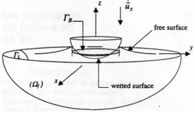
The flow generated during the impact of a body on a free surface is considered. The fluid is assumed to be perfect and incompressible, and the flow is irrotational. The velocity field can therefore be evaluated according to v = grad(/J , where l/J=t/J(x,y,z,t) is the velocity potential. The body shape is assumed to be given by its position
u$
=u$(x,y,z,t)
and the notation z=h(x,y,t) is used for the unknown free surface elevation.z
Figure
1.
Geometrical definitionsUnder these assumptions, the velocity potential satisfies the following boundary value problem :
�l/J=O aq, .:.
-an =us.n
a4'
+
.l(griid(/J)2+.E..+
gz =0
ar
2
p dh = aq, dt ar in.q.
(1)
on the body(2)
on the free surface
(3)
on the free surface
(4)
Equation
(2)
states the continuity of the normal velocity on the body. The kinematic and dynamic free surface conditions, eq.(3)
and(4)
respectively, express that the free surface is a material surface with constant pressure. In the far field, the fluid is assume to be at rest:and the following initials conditions:
h(x,y,O)=O t/J(x,y,z,O)=O
are imposed in the case of a fluid initially at rest. Once the potential is known, the pressure on the body can be derived from Bemoulli's equation:
P aq,
1
_ 2- = ----(grad4J) - gz
2.2 Asymptotic formulation
.
As mentioned earlier, numerous difficulties arise if one wish to solve directly the unsteady nonlinear boundary value problem. Indeed, the motion of the free surface is violent. Experimentally, jets
_developing along the body are observed (see e.g. Greenhow,
1987).
Classically, according to Wagner
(1932),
the problem is simplified into:�l/>=0
dl/J :.
-an
= us.n
l/>=0
dh = dl/>
dt dZ
(6)
onrs(7)
(8)
(9)
where r8 and rL are respectively the projections on the plane
z
= 0 ofthe wetted body surface and the free surface. The contact line fTt),
defined as the intersection between Ts and TL , is a priori Unknown.
The simplified problem
(6)-(9)
requires gravity effect andquadratic terms to remain small compare to the linear terms. The ·
displacements of both, the body and the free surface, must also remain small to justify the geometrical linearisation of the boundary conditions. These assumptions can be justified formally through an asymptotic analysis of the impact problem for a blunt and rigid body
(Cointe,
1989,
Wilson,1989).
The small parameter used in theasymptotic expansion is the ratio between the immersion and characteristic length scale of the body wetted area. The method of matched asymptotic expansions leads then to define three different zones in which three asymptotic expansions are performed and matched successively:
• the far field domain, where the flow is similar to the that
around a flat plate of unknown width in an unbounded fluid,
• the spray root domain near the contact line, where the flow overturns to create a jet,
• and the jet domain, along the body.
The perturbation procedure relies strongly on the blunt body
assumption. In the far field, the body boundary condition
(2)
can bewritten on the undisturbed position of the free surface without
introducing significant error, therefore justifying eq.
(6).
To theleading order, the quadratic terms in eq.
(3)
and (4) can be neglectedin the far field, but must be retained to describe the flow within the
jet. The exact dynamic condition, eq.
(3),
has been replaced by aDirichlet condition for the potential on the undisturbed position of the
free surface. Equation
(7)
is therefore applied onz
= 0. Physically,the acceleration in the fluid has been assumed to be large compared to gravity. For a body impacting the free surface with constant speed
V,
this assumption is justified until g. tiV < < 1. Finally, the simplifiedkinematic free surface condition states that the vertical displacement of the free surface is equal to the fluid vertical motion, evaluated on the linearised position of the free surface.
Within this modelling, the solution is singular on the contact line since the slope of the free surface and the vertical velocity tend to infinity. This singularity is physically correlated with the existence of a jet located near the intersection between the free surface and the body surface. This singularity also appears in the pressure distribution given to the leading order by :
dfP
p=-p
dt
(10)
In the present modelling, the far field solution for the pressure is matched to the asymptotic splution describing the flow in the spray root domain. The resulting composite solution is therefore regular and can be integrated to evaluate the corresponding impact loads.
At this stage, it is important to note that the three dimensional character of the flow has been retained in the equations. In particular, Laplace's equation is not simplified into its two dimensional form as would be usually done using strip theory based on slender body
assumption (see e.g. Fontaine et at
1997).
3 NUMERICAL RESOLUTION 3.1 Variational formulation
The weighted residual method consists in searching for
functions
l/>
that cancel the integral quantity:W
((/�)
=i
q> •R((/J) dD
(1 1)
n/
for all weighting functions q>. For our problem, the residue R(
l/>)
is setequal to
L1lf>.
After applying Green's identity and taking into accountthe boundaries conditions, the integral eq.
(11)
gives:(12)
The discretization of this equation is performed' using Gal er kin's
method. The potential
q,
and the weight functions q> are approximatedusing the same shape functions according to
(13)
The functions N1 depend on the types of elements, and
{ l/>t
denotesthe nodal potential vector of the finite element (e). Using these
approximations into eq.
(12)
leads to linear matrix system for theH{Q>} = {G,}
H� =foe N;,JNJ,;dD
{G� }e = fr• {N, }(�1.n)dSB
3.2 Determination of the wetted surface
(14)
(15)
(16)
To evaluate the right hand side of eq. (16), it is necessary to
know the wetted portion of the body, or, equivalently, the position of
the contact line between the body and the fluid. Due to the
deformations of the free surface, the wetted surface is part of the
unknown of the problem. An additional equation is therefore needed
to close the problem. Physically, the contact line is determined by
·
imposing to the solution to satisfy volume of the fluid conservation
(Wilson, 1989, Fontaine
&Cointe, 1992) or equivalently, by
imposing the existence of an intersection point between the elevation
of the free surface and the body as intuitively done by Wagner
(1932). Volume conservation should be automatically satisfied since
Laplace's equation is solved. Nevertheless, the problem is singular at
the initial time when the contact line reduced to a single point, thus
the need for an extra closure equation. As suggested by Korobkin
(1982), it is easier to introduce the displacement potential given by:
1f!(x,y,z;t)= f�tJ>(x,y,z;s)ds
(17)
instead of the velocity potential. The boundary value problem
satisfied by
1f1is similar to the one satisfied by
Q>except for the body
boundary condition. The main advantage of introducing this
transformation is that the value of
1f1on
z = 0is by construction the
free surface elevation. Solving for
1f1does not require the knowledge
of the temporal evolution of the free surface elevation. From a
numerical point of view, the same discretisation scheme is applied to
the displacement potential leading to:
H{lfl) =(G.,)
(18)
where the discretised body boundary condition writes:
(19)
The wetted surface is determined through an iterative procedure:
starting from an initial surface guess for (T8)0, the problem for
displacement potential problem is solved until that the free surface
elevation is equal to the position of the body at the boundary
fTt) :(20)
Once convergence has been reached, the position of the contact line
is known. the linear system for the velocity potential is then solved. It
is worth noting that the matrix
Hwhich depends only from the
geometry has already been assembled and so doesn't have to be
computed once again to solve the velocity potential problem. From
one time step to the other, the boundary mesh doesn't move, and
therefore no substantive derivative has to be introduced. As a result, a
simple first order backward finite difference scheme give an accurate
estimation of the pressure even close to the singularity as will be
demonstrated in the next section.
4 VALIDATION OF THE NUMERICAL PROCEDURE 4.1 Two dimensional case
The example of a two dimensional parabolic hull defined by
z=a/,
penetrating with constant velocity V a free surface initially at
rest, is considered. The numerical method previously described has
been applied to this case. Comparisons between numerical and
analytical results are presented in fig. 2 and 3. Triangular and
quadrilateral elements were used for the numerical computation.
0.1 ,..---r---, 0.05
�
0 "' 0 0.1 analytical numerical 0.2 0.3 y(m) 0.4 0.5Figure 2.
Comparison between numerical and analytical solutions for the free surface elevation around a parabolic hull.4 ··· ··· ··· 35 . · analytical 3-numerical · error(%)
11
"i::"25 ..�
..�
2-�
�1.5 ... 1 .. ··· ···· ··· ·· ···2 0ti::
)
.14 !12�. l�:
.
i�o�
6i4
•:
������-:.;
...u��.
,..!JJ;J:
0 0.05 0.1 0.15 0.2 y(m)Figure 3.
Comparison between numerical and analytical solutions for the outer pressure distribution on a parabolic hull. The errQrThe analytical expressions for the wetted width, the free surface elevation and the outer expansion of the pressure are classically given
by (Cointe,
1989):
·d2(t)
= 2Vt
a
h(y,t) = -Vt-
[
ra
y(al- 2Vt))'i- al]
P0.,,(y,t) = P
1V2(a(2Vt- al)�
(21) (22)
(23) Although the solution is singular at the intersection, the numerical scheme gives a relatively good estimation of the pressure distribution in this region. Practically, the error increase near the singularity has no real implications since the numerical solution is matched to the nonlinear spray root solution.
4.2 Three dimensional axlsymmetric case
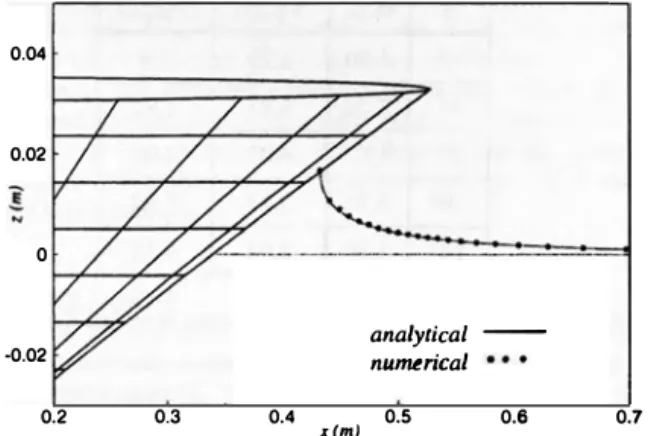
Comparisons for a cone shaped hull are presented in fig. 4 and
5.
Hexahedron types of elements were used in the numerical simulation. Good agreement between numerical and analytical results is obtained again. All parameters being comparable to the previous two dimensional computation, the relative error remains of the same order, despite the mesh is this time really three dimensional. In fig.
6,
the pressure distribution for a two-dimensional wedge and a cone having the same immersion are compared to estimate roughly three dimensional effects. The maximum error on the pressure distribution is around30%.
The figure also shows that the two dimensional computations appears also to be conservative.0.04 0.02 0 ..0.02 0.2 0.3 0.4 x(m) analytical - numuical 0.5 0.6 0.7
Figure 4. Comparison between numerical and analytical solutions for the free surface elevation around a cone shaped hull
To conclude this section, analytical and numerical results are very close to each others for both 20 and 30 cases. The evaluation of the free surface elevation remains nevertheless sensitive to the boundary between the structure and the fluid. To represent the singular behavior of the solution in the vicinity of this boundary, the finite elements mesh has to be refined in this zone. The regularity of the mesh is also an important parameter which controls the accuracy of the numerical resolution.
:r
anorync�
l--=
----nn�:
16�
numerical16
14
�
error(%)11
14
8
6
4
2 ·12_
oo�wu�o�.1ww�o�2�Ld�WL��o
y(m}Figure
5.
Comparison bet�en numerical and analytical solutionsfor the outer pressure distribution on a cone shaped hull
%�
�0�.2��0.�4��0�.6--�0.�8��
.v(m)Figure
6.
Comparison between the pressure distributions along acone and a wedge penetrating the free surface with same velocity. At each time, the immersion is the same for the two bodies
5 EXPERIMENTS 5.1 Experimental set-up
Free fall drop test experiments have been carried out on the
impact tower of the Fluid Dynamics Laboratory. at the Ecole Centrale
of Nantes (see fig.
7).
The use of a relatively large experimentalfacility ( 10 m height and
1
,4 m width) allows for a typical size of0.32m for the tested models, therefore reducing the possible influence of surface tension effects.
Cable
(j)
-.r+--+-t---- pliers®
n==;::�l�tj�--
Guided frameFigure
7.
Impact tower: experimental set-upCones shaped models were rigidly attached to a cylindrical support
itself connected to the guided frame of the
impact tower. The models
were set free without initial velocity by means
of pliers �operated
by two
hydraulic jacks.
During thedrop, the cone was guided by a
system of cables <V
which
allowsto control the relative position
between the body and the free surface. After impact into water
surface, the cone was
stopped progressively by a metallic frame
covered with foam.
Three different cone shaped
models with deadrise angles of 6,
10, and 14 degrees have been successively tested (see fig. 8). The
effective thickness of the steel models
were sufficiently important,
reaching from
25
to50
mm, so that therigid body assumption is
verified during impact. The aim
of this first set of experiments is to
test the accuracy and domain of validity of
the simplified numerical
method previously described, but also to prepare
more complex
experiments to study the influence of hydroelasticity effects. The impact velocity was chosen to rise realistic values from
3 to 6 m/s
approximately.
The drop height of the model was set up to 3.0 m.
Due to rubbing of the pulley-cables connections,
additional
weight were necessary to reach the desired impactvelocity.
Cone
I.
I
Sensor 2 Sensor 1I
�A�--- .
_.·.__ ���·, �· ... ,� .... ' .---n.----40 e = 16Figure
8.
Detailed views of the cone shaped models with differentdeadrise angles
Drop velocity and pressure
measurements
were performedduring impact. Two quartz ICP
compensated pressures sensors were
set at 40
mm and90 mm from the cone symmetry axis (fig. 8). These
sensors are well suited for impact measurements.
Their samplingfrequency is up to
400 kHz,and the measurement range
is0
to69
bar. They also allow for the use of relatively long
wires(20
m)without altering the electric signal
so that the data processing systemdoes not need to be too close to the
water.The drop velocity was measured by mean of a dynamo connected to
the guidance pulley of the cable.
Finally, pressure and velocitysignals are plotted
and recorded by a numerical memory oscilloscope.The cones were dropped against
calm water. At least three drops were performed ineach test
condition to make sure of the repeatability of the measurements. Results presented below are representative' of these drop test series.5.2 Comparisons between theorv and experiments
Table 1 reports the main parameters of
each experiment, i.e. thedrop height
(H)and the falling velocity at the initial time
of impacton sensor 1 and sensor
2.The two maximum values of
the pressure atthe two locations, measured and calculated, for
the three deadriseangles
(�) are presented in table
2.Numerical and
experimentalresults for the pressure levels are found to be in reasonable
agreementalthough the pressure is always slightly over predicted, indicating
thatthe numerical model is therefore conservative.
On the first sensor, and for the
sm
allest deadrise angle, theexperimental value is by far over predicted.
Physically, it is believedthat air entrapment
occurs, leading to a decay of the pressure. Thisphenomenon has also been observed by Chuang (1971)
on cones withdeadrise angles smaller than 1°, and
by Hagiwara, Yuhara(1974)
forwedges with deadrise angles lower than 3
degrees.�
Hcml vl(m/s) v2(mls)60
1,80
3,79
3,9
60
2,705,87
5,9
2 IQO1,80
4,03
4,08
IQO 2,705,87
5,92
14°
1,80
3,94
4,16
Table 1.
Measured velocities for different free fall drop heightsP1 (bar) P2 (bar)
�
Exp.
Nu m.
Exp.
Nu
m.60
7,8
10,5
8,3
11
60
15
25,3
26,4
25,7
IQO3,5
4,25,2
4,3
10°
7,8
9
10,6
9,1
14°
1,3
21,7
2,2
Table
2. Experimental-numerical pressures levels comparison for different heights of impactsExamples of temporal evolution of the pressure on the two
probes are presented in fig. 9 (a) to (e) corresponding to the different
deadrise angles and impact velocities. Although experimental and
numerical distribution pressures don't fit exactly the same in details,
the experimental distribution is globally well represented by the
'numerical simulation. Both signals show a pressure peak travelling
along the body, followed by a plateau. The location of the peak is
clearly well described by the simplified theory. The wetted length
seems therefore to be correctly estimated. This local qJ.Iantity results
nevertheless from global volume conservation property as mentioned
previously. It is therefore not surprising that the modeling is able to
give a good estimate of this quantity. The pressure rise immediately
after impact is also well reproduced. The simplified model is indeed
asymptotically valid for small times. The level of the peak, i.e. the
maximum pressure, is reasonably estimated for the smallest deadrise
angle, but the error increase with an increase of the deadrise angle.
According to the asymptotic solution, the level of the pressure peak
should not vary along the body. The experiments clearly indicate that
the peak intensity increases between the two probes. This discrepancy
can be partially explained by the fact that the impact velocity of the
cone is also increasing due to gravity acceleration. This phenomenon
is not reproduced in the numerical simulation where the impact
velocity remains constant. A posteriori calculus confirms that the
velocity increases immediately after impact, the acceleration
decreasing but remaining downward. The plateau level is also slightly
over estimated, certainly as a result of using a simplified body
boundary condition. It is well know that the geometrical linearisation
of the boundary condition yields to an overestimation of the pressure
coefficient (see e.g. Faltinsen, 1997, Fontaine
&Cointe, 1997).
Secondly, we observe two zones where oscillations are
generated. In the first zone we couldn't give definitely an explanation
for this oscillations. In the second zone, the oscillations correspond
not only at the moment when the cylindrical support come into the
water but also to the flat circumference. Then, this is the body
geometry which generates the second zone oscillation.
Even if the different experimental results outline above are
rather good, examination of the angle impact, who doesn't fit exactly
with the real one, prevent us to validate wholly the experimental
investigation. We are now setting a new scheme which allows to
control this parameter.
6 CONCLUSION
In the present paper, the three-dimensional Wagner problem is
solved numerically using a variational formulation together with a
finite element method. The so-called wetting correction is obtained
through an iterative procedure. The numerical resolution is validated
computing simple problems, such as the water impact problem of a
wedge with small deadrise in the two dimensional case, or a cone for
the three-dimensional case. Good agreement is obtained between
numerical and analytical solution. This paper also describes a first
series of drop-test experiments. These drop-tests consist in the
impacts of rigid cones on a free surface initially at the rest.
Experimental histories are well predicted by numerical pressure
simulations, although differences are reported. In particular, it has
been found a dissimilarity between peak pressure values (the first
peak being weaker than the second), resulting from an increase in the
velocity. The retardation effect, resulting from impact loads, appears
latter on in the experiments.
We are now leading new drops-tests investigation for which
measurement of the velocity is made by incremental coder. It allows
us a more accurate analysis of results.
7 ACKNOWLEDGMENTS
The authors gratefully acknowledge the financial support of
French Direction Scientific of the Delegation Generale de
l'Armement.
8 REFERENCES
Cointe, R., Armand, J.L., 1987, "Hydrodynamic impact analysis of a
cylinder"
J. Offshore Mechanics and artic Engineering,vol. 9, pp.
237-243
Cointe, R., 1989, ''Two dimtnsional water solid impact"
Journal ofOffshore Mechanics and Arctic Engineering,
vol.l l 1, pp.1 09-114
Chuang, S.L., 1967, "Experiments on slamming of wedge- shaped
bodies"
Journal of Ship Research,pp. 190-198
Chuang, S.L., Milne, D.T., 1971, "Drops test of cones to investigate
the three-dimensional effects of slamming"
Navy Naval ShipResearch and Development Center, Report 3543
Donguy,
B.,Peseux, B., Fontaine, E., 2000, "On the ship structural
response due to slamming loads "
Proc. of European Congress on Computational Methods in Applied Sciences and Engineering,Barcelona
Faltinsen,
0.,Zhao, R. 1997, "Water entry of �hip sections and
axisymetric bodies"
High Speed Body Motion in Water,Kiev
Faltinsen,
0.,1997, 'The effects of hydroelasticity on ship
slamming"
Phi/. Trans. R. Soc. Lond.,vol. 355, pp. 575-591
Fontaine, E., Cointe, 1997, "Asymtotic theory of water entry",
HighSpeed Body Motion in Water,
Kiev, NATO conference.
Greenhow, M., 1987, "Wedge entry into initially calm water"
Applied Ocean Research,
vol. 9, pp. 214-223
Hagiwara, K., Yuhara T.,1974, "Fundamental study of wave impact
loads on ship bow"
Journal of the Society of Naval Architectvol. 135
Howison, S.D., Ockendon, J.R., Wilson S.K., 1991, "Incompressible
water entry problems at small deadrise angles"
Journal of Fluid Mecha
nics,vo1
.222,pp. 215-230
Korobkin, A.A., 1982, "Formulation of penetration problem as a
variational inequality"
Din. Sploshnoi Sredy,vol. 58, pp. 73-79
Magee, A, Fontaine, E, 1_998, "A cou
p
led approach for the. evaluati.on
of slamming loads on shtps"
Proc. 7t lnt. Symp. on Practzcal Deszgnof Ships and Mobil Units,
The Hague Netherlands
Korobkin, A.A., 1995, "Wave impact on the bow end of a catamaran
wetdeck"
Journal of Ship Research,vol. 39, pp. 321-327
Wagner, H., 1932, "Uber Stoss und Gleitvorgange an der Oberflache
von Fltissigkeiten"
Z. Ang. Math. Mech.,vol. 12, pp. 193-215
Wilson, S.K., 1989, 'The mathematics of ship slamming"
Ph.D. thesis, University of OxfordZhao, R., Faltinsen, O.M., Aarsnes, J.V., 1996, "Water entry of
arbitrary two-dimensional sections with and without flow separation"
& �. -.---�---.---,---�--�
(b)
I
5 f- ---·---1--..,..----+----l----1 12,---�---�---.---,(c)
r 10 r---- ___ . ---l--1---+---l pressure on sensor pl pressure on sensor p2 numerical simulation .---.---·-�---·---·-· 101---ll---t 81---(d) (e) 24�-�---�-�----�----�!
20 1---�i----___....__j_
___________ i --··----· -. I If
�----��---�·---· --'---.1
t
1----&---iM--+------r---
_,Figure 7. Pressure histories (a) cone 14°- (b)-(c) cone 10°- (d)-(e) cone 6° (I) velocity during all the drop test