HAL Id: hal-01991725
https://hal.archives-ouvertes.fr/hal-01991725
Submitted on 4 Feb 2019
HAL is a multi-disciplinary open access
archive for the deposit and dissemination of
sci-entific research documents, whether they are
pub-lished or not. The documents may come from
teaching and research institutions in France or
abroad, or from public or private research centers.
L’archive ouverte pluridisciplinaire HAL, est
destinée au dépôt et à la diffusion de documents
scientifiques de niveau recherche, publiés ou non,
émanant des établissements d’enseignement et de
recherche français ou étrangers, des laboratoires
publics ou privés.
Overview and Measurement of Mobility in DASH7
Wael Ayoub, Fabienne Nouvel, Abed Ellatif Samhat, Jean-Christophe
Prévotet, Mohamad Mroue
To cite this version:
Wael Ayoub, Fabienne Nouvel, Abed Ellatif Samhat, Jean-Christophe Prévotet, Mohamad Mroue.
Overview and Measurement of Mobility in DASH7. 2018 25th International Conference on
Telecommu-nications (ICT), Jun 2018, St. Malo, France. pp.532-536, �10.1109/ICT.2018.8464846�. �hal-01991725�
Overview and Measurement of Mobility in DASH7
Wael Ayoub
∗†, Fabienne Nouvel
∗, Abed Ellatif Samhat
†, Jean-christophe Pr´evotet
∗,and Mohamad Mroue
†∗Institut National des Sciences Appliqu´ees de Rennes — IETR-INSA, Rennes, France. † Faculty of Engineering - CRSI, Lebanese University, Hadath Campus, Hadath, Lebanon
Email∗: [email protected] Email†: [email protected], [email protected]
Abstract—Recently, the evolution of low-power wide area net-works (LPWANs) provides Internet of Things (IoT) with an approach between the short range multi-hop technology and the long-range single-hop cellular network technology. LPWANs provide connectivity by using long-range communication with low data rate in unlicensed bands. They are developed to satisfy the requirements of IoT communication needs, but less attention is given to the mobility of the End-Devices (EDs). In this paper, we consider DASH7 which is a well-defined LPWAN standard provided by DASH7 Alliance. After a brief overview of this technology, we focus on EDs mobility to show how the mobility can be achieved while transmitting data. An appropriate testbed is setup for testing. Experimental results show the mobility delay time for an ED to switch between two gateways (GWs).
Index Terms—IoT communication, LPWAN, DASH7 alliance protocol, Mobility.
I. INTRODUCTION
By 2020, there will be billions of smart things connected to Internet with high potential economic impact, according to Cisco’s expectation [1]. A massive part of this expectation is to be covered by Wide Area Networks (WANs). In addition to cellular networks, several Low Power Wide Area networks (LPWANs) [2] have appeared and they are gaining a significant part of the market in the recent years. These networks are specified for connecting things to Internet and recognized as IoT (Internet of Things) protocols. From these protocols, a well-defined LPWAN standard is the DASH7 Alliance Protocol (D7AP). D7AP [3] is an open source Standard for bi-directional Wireless Sensor and Actuator Network (WSAN) applications. It operates in the Sub-1 GHz bands based on the ISO/IEC 18000-7 [4] standard and specified by the DASH7 Alliance. The ISO/IEC 18000-7 standard defines the parameters of the active air interface communication at 433 MHz. D7AP inherits the default parameters from ISO 18000-7 and extends the standard by defining a complete communication stack from the application layer to the physical layer [5]. This stack contains a high level of functionality optimized for active RFID and WSAN. Also, it ensures interoperability among different oper-ators. Conversely to legacy RFID systems [6], D7AP supports tag-to-tag communication. In 2013, D7AP 0.2 was published by the DASH7 Alliance. The last version, D7AP 1.1, was published in April 2016. Table I summarizes the specification of the DASH7 wireless technology. D7A mediates between the short range area networks such as Bluetooth, Zigbee, etc. and the long ones like LTE or 3G. D7A outstrips in industrial and urban network installations enabling the connection of actuators
TABLE I
D7A PROTOCOLSPECIFICATIONS
Specification DASH7 technology Support Standard ISO/IEC 18000-7 Operational Frequencies 433.92, 868, 915 MHzUnlicensed ISM band Modulation 2-GFSK Coverage Range (Km) 1 - 2 (extend usingsubcontroller) Data Rate (kbps) (16, 8, 4 channels)13, 55 ,200 Topology Tree, Simple routing 2 hops
and messaging applications (sensors, alarms, states), exceeding ranges up to 1000 m. For low data rate, the link budget can exceed 125 dB with a 14 dBm transmission power. It also allows over-the-air (OTA) code upgrade and reactive downlink access. D7A is named as Bursty, Light, Asynchronous, Stealth and Transitive (BLAST) network technology. Bursty refers to transmitting short and sporadic sequences of data. D7A speci-fies a small packet size limited to 256 bytes, which is considered as Light. The communication is asynchronous, and is based on a command/response approach with no periodic synchronization. It is stealth because devices do not need periodic discovery beacons to be able to respond in communication. It is defined as transitive because D7A supports mobility. End-devices can move within different GWs coverage.
In this paper, we consider the mobility of EDs between two GWs through an experimental study. We investigate the WizzKit features which is an implementation of D7A [7] and we measure the mobility delay time for an ED moving between GWs. The paper is organized as follows. We first describe the D7AP network implementation in section II and provide details about the architecture, equipments and used protocol. In section III, we present the testbed and the experimental study. In section IV, the mobility of EDs in typical scenarios is discussed. Finally, Section V draws a conclusion.
II. D7AP NETWORKIMPLEMENTATION
A D7A network is composed of sensor nodes, actuators and gateways that are connected to a web service in the Cloud, as shown in Fig. 1. One of the suppliers of full D7A network equipments is WizziLab [7]. It provides the WizziKit which is a full Wireless Sensor-Actuator Network, with services for fast and easy network deployment. WizziKit supports D7A over LoRa [8] which is an extension of the D7A physical layer in
order to use LoRa modulation. This is useful to benefit from a long range communication but it also leads to increasing the power consumption and packet duration. All features of D7A are still conserved and the link budget can be increased beyond 160 dB with a transmission power of 14 dBm. The WizziKit firmware is compatible with the D7A Specification v1.1 that was released in January 2017. The Wizzikit components can operate in the 868 MHz ISM band for Europe or in the 915 MHz ISM band for USA.
A. Architecture
The D7AP Architecture consists of EDs and GWs that are de-ployed in a star network as shown in Fig. 1. EDs communicate with D7A-IP GWs and these GWs are connected to a WizziKit Cloud Service using the MQTT protocol [9]. This protocol is a lightweight publish/subscribe messaging transport used to handle simultaneously up to thousands of connected MQTT clients. The Cloud server provides a simple XML configuration framework to set up sensors, control the actuators and monitor the data that are received from EDs and GWs.
Fig. 1. DASH7 Alliance Protocol Architecture [7].
B. Equipments
To test the D7A network, we used the Wizzikit which is composed of:
Dash7 Gateway (GW): The GW2120 is a fully integrated DASH7 Gateway that operates in the 868 or 915 MHz ISM bands. This GW is based on the GL-iNet AR150 Smart Router with enhanced MQTT firmware. It can be controlled directly from its on-line interface and configured for bi-directional communication with any D7A with FSK modulation or D7A with LoRa modulation. This gateway can be connected to the Internet either by Ethernet or Wifi. After connection establish-ment, data are sent to the cloud server over the MQTT broker. At the physical layer, it may use the 2-FSK, GFSK, and LoRa modulation schemes. It can be configured to transmit data either based on FSK data rates 9.6 / 55.6 / 166.7 kbps or based on all LoRa data rates.
DASH7 Node (ED): The node is based on Nucleo Shields (SH2050) connected to Nucleo L432KC [10]. Nu-cleo L432KC is based on a STM32L432KC micro-controller (ARM Cortex M4) and MBED enabled the STM32L432KC. The Nucleo L432KC is compatible with the SH2050 DASH7 Communication Shield. The Nucleo Shield (SH2050) features a full LoRaWAN protocol stack that is configured as a Class A ED and compatible with D7AP v1.1. ED data are sent to the dash7board through one GW. The SH2050 provides a DASH7 modem and a bunch of sensors to the Nucleo L432KC. The on board sensors are:
• accelerometer / magnetometer (LSM303C) • barometer (LPS25HB)
• humidity and temperature (HTS221) • Visible Light Sensor (TEMT6000)
Wizzlab provides a free access to Dash7Board cloud Network service (NS) with the Wizzikit. This NS handles the network management, security, device version, data decoding, and data routing.
C. Communication
An ED can be seen as a file system. Communications between an ED and a GW in D7AP can operate in two modes: i. Push mode, used by an ED to send data to a GW using tag-talks-first scheme, as shown in Fig. 2 (yellow notification). ii. Pull mode, which is based on a request/response mechanism. It is initialized by the GW or the NS (green, blue and violet).
Fig. 2. DASH7 Alliance Protocol Communication Model [7].
III. DEFINEDSCENARIOS ANDMEASUREMENT RESULTS In this work, our purpose is to investigate the mobility in D7AP through experimentation. Mobility management in IP networks has to provide seamless connectivity during IP handover, whereas in IoT, it consists in sensing an ED to send data to a remote client when requested. Thus, mobility in the IoT environment is different from the mobility management found in IETF [11] protocols. The ED mobility will be tested using the Wizzikit. Fig. 3 shows two cases: i. case 1 where the coverage of the two GWs is with overlap. ii. case 2 in which there is no overlap between the coverage of the two GWs. With
respect to the first case, we denote by ”uplink” direction the data transfer from an ED to a GW, and by ”downlink” the opposite direction (GW to ED).
Fig. 3. Studied cases to test mobility.
A. Range Test
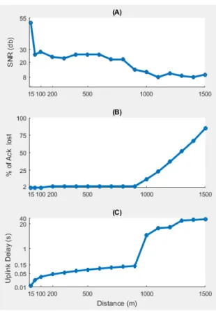
Before starting with mobility, we installed one GW at the top of our department building at the university (height = 21.5 m), then we moved the ED around, in a line of sight (LOS) trajectory, going up to 1.6 km. During the movement, we made sure that both ED and GW were communicating in LOS. The ED was configured to transmit the temperature value in uplink. The value consists of a 4 bytes payload and was sent every 30 seconds. All other configurations have been left to default. The uplink data were monitored using the Dash7 cloud server (NS). During testing, we have noticed that, at the distance of 1600 m, the GW was still able to receive uplink data from the ED, but the ED was not able to receive an acknowledgment (ACK). Fig. 4-a shows the measured SNR in dB, when the ED moves from a range within 15 an 1500 m. Note that, as expected, the SNR decreases when the distance increases and the communication undergoes high degradation when SNR is below 8 dB, which corresponds to a distance greater than 1000 m. As the ED is not receiving an ACK at this distance, it repeats non-ACK uplink until the number of repetitions runs out or drops data when queue is full.
Fig. 4-b and -c, show the percentage of ACK loss and the uplink delay, respectively. For a distance less than 1000 m, the ED receives ACKs from the GW on time. When the distance increases beyond 900 m, the number of ACKs loss increases exponentially until it reaches 90% at 1500 m. As the number of repetitions increases, repeated uplinks cause delay for the subsequent data. This delay increases until it becomes twice the value of the time required in the uplink phase. As shown in Fig. 4-c, at the distance of 1300 m, the uplink delay is 36 s. B. Mobility
Our testbed is shown in Fig. 5. The WorkStation (WS) is installed between the GWs and the NS. This WS acts as a router that provides Internet connection to the two GWs: A2 and
Fig. 4. Results related to testing the range.
9E. It is connected to Internet using a WiFi card and provides the connection over the Ethernet port. On the WS, we use Wireshark [12] program to monitor sent/received packets on the Ethernet port. On Wireshark, we can detect and determine when the ED switches between the two GWs. Then, we calculate the time of this switching (Mobility time). We have installed both GWs with a distance of 1000 m between them to ensure dealing with the mobility of case 1 as shown in Fig. 3. We start moving from GW A2, which has an IP 192.168.137.2 to GW 9E that has the IP 192.168.137.3.
1) Downlink (Request-Respond): GW A2 requests the value of temperature from the ED. This query is written, generated and transmitted using the MQTT client found in the GW. Fig. 6 shows the request (number 3) sent by the GW to the ED. Then, the ED provides a response to GW A2. This response is used to indicate that the request has been received (number 4). A special TAG Action with the requester (ID=c3) is inserted at the beginning of the Application Layer Protocol (ALP) Command to be marked. After processing, the ED returns the value of the temperature to the GW (number 8). Finally, the ED terminates the process (number 11). The overall duration of the process is shown in Table II and in the Gantt chart depicted in Fig. 7.
Fig. 6. Request/Response Packets.
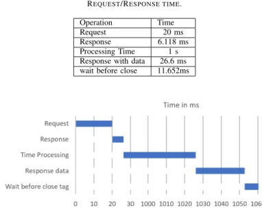
The values shown in Table II are the average values for the tested request/response commands that have been repeated 10 times. The time between a GW request and an ED response is 26.118 ms. Then, the ED requires 1.0266 s for data processing and responding. Finally, the ED waits for 11.652 ms to get new data from the GW. It then closes this tag ID.
In reality, the request is generated by the Application Sever (AS) or a Cloud user that is connected to a NS. A forwarding table on the NS is used to route the downlink messages. For every ED, this table contains the nearest GW address. This table is generated and periodically updated or checked every time uplink data are received. In the case where an ED broadcasts uplink data, a NS may receive the same uplink data from multiple GWs. Then, the NS selects one of the GWs based on the highest RSSI and sets its address in the table as the nearest GW to this ED.
When the AS generates the request, the time value is equal to that stored in Table II plus the time delay between the GW and the AS. This delay depends on the link speed between the WS and the NS. An easy way to measure this delay is to ping
the NS IP address from the WS. In our case the average time is equal to 200 ms.
TABLE II REQUEST/RESPONSE TIME. Operation Time Request 20 ms Response 6.118 ms Processing Time 1 s Response with data 26.6 ms wait before close 11.652ms
Fig. 7. Gantt chart for Request/Response Time.
When the ED moves to the coverage of GW 9E without transferring any data, requests will be forwarded by the NS to the GW covering the previous location of the ED. In such a case, no response will be received. The NS will consider the device as unreachable and will send a ”Device Unreachable” message to the AS. Then, it will wait until new uplink data are received from this ED to update the forwarding table.
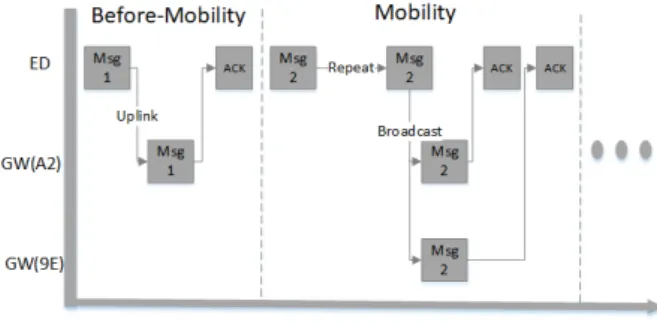
2) Uplink (Notification): AN ED is configured to provide a temperature value (4 bytes of data every 5 s) As shown in Fig. 9-(Before-mobility), the ED sends data to GW A2. During its movement, at a distance of 800 m from GW A2, the ED sends an uplink ’Msg 2’ but no ACK is received from GW A2 as shown in Fig. 9-(Mobility). In this case, the ED repeats the same uplink transmission in broadcast. These repeated uplink data are received by both GWs. As shown in Fig. 8, uplink data appears on the sequence number 202 by GW 9E and 208 by GW A2, whereas the original message was 195. Then each GW replies with an ACK to the ED. This procedure is repeated 15 times. The time needed to switch between the two GWs is 305 ms. It represents the mobility time in D7AP.
Fig. 8. Mobility time delay extraction.
IV. EDMOBILITY IND7AP
Consider a scenario including three GWs and two EDs. Each ED is installed in a car; the first one is yellow and the second
one is black as shown in Fig. 10. First, let us consider that the yellow car moves from GW2 towards GW1. At position A, the ED turns on and broadcasts an uplink message. In this case, only GW2 receives the message and sends back an ACK message. Thus, the ED selects GW2 to forward all the subsequent uplink data. During the movement, the yellow car reaches position B. The ED continues to send uplink messages to GW2 as long as ACK messages are received back from it. This occurs even if the RSSI of GW1 is greater than that of GW2 at this position. At position C, GW2 is out-of-range and the communication between ED and GW2 is lost. In the absence of an ACK message from GW2, the ED switches to broadcast mode. In this case, only GW1 receives the uplink message from ED and sends back an ACK message. Then, all next uplink data will be sent to GW1. Consider now the case of the black car
Fig. 9. Reporting before/ in Mobility.
Fig. 10. Mobility in D7AP network.
that is moving from GW1 towards GW2 and passing through an area covered by all the three gateways, GW1, GW2, and GW3. At position D, the ED starts broadcasting an uplink message in order to select the best available GW. It ends up by selecting the only available one, GW1. At position E, the ED continues to communicate through GW1 as long as it receives ACK from GW1, even if it is now in a zone covered by both GW1 and GW3. At position F, GW1 is now out-of-range and the communication is lost. The ED switches into broadcast mode and repeats the uplink data till receiving an ACK from any GW in range.
Meanwhile and before selecting a particular GW by an ED, the NS detects and removes any duplicated broadcast messages. Then, GW3 and GW2 will acknowledge. The ED selects the GW with the highest RSSI, GW2 in this case. At position G,
nothing changes and the ED continues to communicate through GW2.
Using Wireshark, the total time delay required to re-establish the communication in case 1 (with GWs coverage overlap) is around tm = 305 ms. For case 2 (without GWs coverage
overlap), the delay equals to tmplus the time duration ti spent
by the ED in the uncovered zone. The time ti is the ratio of
the velocity of the ED over the distance traveled by the ED in the uncovered zone.
V. CONCLUSION
This paper provides the basic details of D7AP and highlights the mobility supported by this technology.After presenting the architecture of this standard, the features of the used devices were investigated. Then, we setup a testbed to run our experiments and test mobility in different scenarios. The results show that the time delay related to mobility is around 305 ms in uplink. For that, DASH7 is not useful for applications that require periodic uplink data with a period shorter than the mobility time delay. The results also show that, in downlink, and after moving out of the range of the current GW, an ED must transmit a message to update its routing location on the NS, otherwise it will be unreachable. In this case, the mobility time delay is related to the time at which the ED sends uplink data in broadcast mode to re-establish the communication and update the routing path in the NS forwarding table. This limitation should also be considered by applications when downlink requests are needed. Future work will focus on this issue in downlink.
REFERENCES
[1] D. Evans, “The internet of things: How the next evolution of the internet is changing everything,” cisco white paper, vol. 1, 2011.
[2] U. Raza, P. Kulkarni, and M. Sooriyabandara, “Low power wide area net-works: An overview,” IEEE Communications Surveys Tutorials, vol. 19, no. 2, pp. 855–873, Secondquarter 2017.
[3] DASH7 Alliance Mode Specification, 2017th ed., DASH7 Alliance Std., ”http://www.dash7-alliance.org/dash7-alliance-protocol-specification-v1-1-ready-for-download/”.
[4] ISO, “International organization for standardization,” https://www.iso.org/standard/57336.html, Sep 2017.
[5] H. Lee, S. H. Chung, Y. S. Lee, and Y. Ha, “Performance comparison of dash7 and iso/iec 18000-7 for fast tag collection with an enhanced csma/ca protocol,” in 2013 IEEE 10th International Conference on High Performance Computing and Communications 2013 IEEE International Conference on Embedded and Ubiquitous Computing, Nov 2013, pp. 769– 776.
[6] H. Lehpamer, “Rfid design principles,” artech House, 2012. [7] “Wizzilab project homepage,” http://wizzilab.com/, 2017.
[8] LoRaWAN Specification, 2016th ed., LoRa Alliance, https://www.lora-alliance.org/lorawan-for-developers.
[9] A. Stanford-Clark and H. L. Truong, “Mqtt for sensor networks (mqtt-sn) protocol specification,” version 1.2, http://mqtt.org/new/wp-content/uploads/2009/06/MQTT-SN spec v1.2.pdf, November 14, 2013. [10] “Arm mbed platform web-page,”
https://os.mbed.com/platforms/ST-Nucleo-L432KC/, 2017.
[11] S. Imadali, A. Kaiser, F. Sivrikaya, N. E. Sayed, M. Boc, W. Klaudel, A. Petrescu, and V. Veque, “A review of network mobility protocols for fully electrical vehicles services,” IEEE Intelligent Transportation Systems Magazine, vol. 6, no. 3, pp. 80–95, Fall 2014.
![Fig. 2. DASH7 Alliance Protocol Communication Model [7].](https://thumb-eu.123doks.com/thumbv2/123doknet/11492469.293070/3.892.472.822.598.822/fig-dash-alliance-protocol-communication-model.webp)