HAL Id: hal-01853142
https://hal.archives-ouvertes.fr/hal-01853142
Submitted on 2 Aug 2018
HAL is a multi-disciplinary open access archive for the deposit and dissemination of sci-entific research documents, whether they are pub-lished or not. The documents may come from teaching and research institutions in France or
L’archive ouverte pluridisciplinaire HAL, est destinée au dépôt et à la diffusion de documents scientifiques de niveau recherche, publiés ou non, émanant des établissements d’enseignement et de recherche français ou étrangers, des laboratoires
Structural wingbox optimization in a coupled FSI
problem of a flexible wing: FEA sol200 versus surrogate
models
Joseph Morlier, M. Charlotte
To cite this version:
Joseph Morlier, M. Charlotte. Structural wingbox optimization in a coupled FSI problem of a flexible wing: FEA sol200 versus surrogate models. 8th International Conference on Engineering Computa-tional Technology (CST 2012), Sep 2012, Dubrovnik, Croatia. pp.1-17. �hal-01853142�
To cite this document: MORLIER, Joseph and CHARLOTTE, Miguel Structural wingbox optimization in a coupled FSI problem of a flexible wing: FEA sol200 versus surrogate models. (2012) In: Proceedings of the Eighth International Conference on Engineering Computational Technology, 04-07 Sept 2012, Dubrovnik, Croatia.
This is an author-deposited version published in: http://oatao.univ-toulouse.fr/ Eprints ID: 7908
Any correspondence concerning this service should be sent to the repository administrator:
Abstract
This work presents a two-step approach that was adopted in a collaborative multi-disciplinary work named OSYCAF for wing-box design optimization. This approach encompasses: 1) the initialization of a full parametric PCL flexible wing optimization with analytical design, and 2) the comparison of the sol200 optimization (mass of the wing) with a simple surrogate model (also known as Reduced Order Model due to the quadratic form in the regression). Our main objective is to optimize the global structure weight while respecting all structural criteria and constraints, and using the spars and skin thickness as design variables. We show that after the optimization the importance of upper and lower skins is minimized and almost all efforts are concentrated on spars, specially the rear spar. It is also shown that the strain criterion is stronger than the stress one, which considers shear and buckling deformations as the critical design points, although fatigue is also relevant when designing the lower Wing-Box Skin. We show the results obtained for the local optimization of several considered NACA-4 profiles by using an automated process.This work is developed such that an association with an aerodynamic approach using CFD would make possible to create a variation of the required profile to construct the real wing that, when deformed, would assume its best shape in terms of aerodynamics, still respecting all structural constraints and minimum weight possible.
Keywords: Flexible wing, wingbox optimization, surrogate model, NACA profiles.
1 Introduction
Designing an aircraft wing is a multidisciplinary process [1, 2] involving complex interdependencies between many design variables that must satisfy specific requirements from structures, aerodynamics, controls, and propulsion domains, for instances.
Structural wingbox optimization in a coupled FSI problem of a flexible wing: FEA sol200 versus surrogate models
J. Morlier1, M. Charlotte, F. Habbib, E. Lima
Université de Toulouse; INSA, UPS, Mines Albi, ISAE; ICA (Institut Clément Ader); 10 av. Edouard Belin, F-31077 Toulouse, France
1 Corresponding author, Email: joseph.morlier@isae.fr, Phone no, + (33)561338131, Fax no, + (33)561338330
Practical coupling of the expert technologies and methodologies of the research and engineering domains is a nontrivial challenging task in the wing sizing optimization process. Some authors [3-6] have described the application of such a collaborative optimization in the process of aircraft design. In multidisciplinary design and optimization (MDO), the current trend is to replace traditional semi-empirical relations by coupled multiphysics simulation codes. Another trend is to substitute the full computation calls by surface response models (RSM, also known as surrogate model or reduced order model) [7] during the optimization process to speed up the MDO loops.
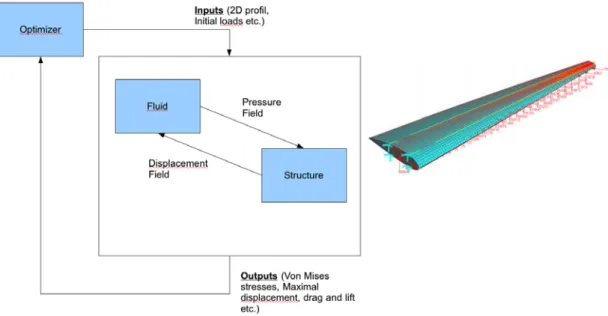
Figure 1 - Common FS optimization of a coupled problem (left) and Complete NACA 2415 wing model ready for analysis (right).
An instance of such multidisciplinary optimization loops that is schematically illustrated on Fig. 1 is investigated in the OSYCAF’s program (see acknowledgements). The aim of this on-going research project is to develop an optimization process suitable for designing flexible aircraft wing structures within a coupled fluid-structure (FS) interaction computational analysis. Unlike other research works that often focus on small size aircrafts, we look for optimizing commercial aircraft wingbox (WB), providing the lowest weight for the entire structure that resists to all loadings, respecting sizing constraints (panel buckling for example) that define a real wing, according to manufactures such as Airbus, Boeing, Embraer and Bombardier. Here, we do not intend to address the robust optimization problem (see [8]), but we discuss about the FS optimization process at transonic regimes under a given flight condition. In the domain of multidisciplinary WB sizing we can cited the work by [9-13].
One main interest into an optimization approach coupling computational fluid dynamics (CFD) with computational structural mechanics (CSM) is to allow variations of the required profile to construct the real wing that, when deformed, would assume its best shape in terms of aerodynamics performances with the possible minimum weight, and still respecting all structural constraints.
To reach this aim, our coupled structural and aerodynamic optimization process of a flexible wing proposes a 2-steps process (metallic through composites) that is described on Fig. 2. The first part of our WB optimization process that corresponds to the left hand side of Fig. 2 deals with metallic material to initialize a detailed analysis combining RSM and finite element analysis (FEA) and optimization with NASTRAN Sol200. The second part of our WB optimization process, which represented on right hand side of Fig. 2 will be presented elsewhere, deals with laminate and curved fiber composite of the WB [14-16]).
At the upper level that is not detailed in Fig. 2, the main objective of this project is to achieve the minimization of both the structural mass and the aero elastic lift.
Figure 2 OSYCAF CSM FRAMEWORK deals with 2 steps wingbox optimization from metallic to l aminates and finally curved fibers composites panel optimization (buckling).
This paper merely focuses on the enhanced structural optimization of the WB on the left path of the Fig. 2. Our goal is to present a reasonable approach to structural modeling in Patran and optimization and design sensitivity in Nastran that may help to validate and improve the analytical equations developed for preliminary design of future aircraft programs. The RSM that is used at the left path of Fig. 2 to speed up the optimization process corresponds to an analytical sizing devoted to explore the design space and identify the robust values for the design variables while evaluating the trade-offs between various objectives, among which the lightless aircraft wing weight is one main objective.
The paper is organized as follows. Section 2 presents the theoretical background of the NACA profil, the FEM used to design the wing and the loads. Section 3 presents the structural optimization process using parametric approaches. Section 4 presents a comparison between RSM and FEM optimization results using Nastran Sol200.
2 Theoretical background
2.1 From NACA profil to WB sizing
Classical literature describes the design process of aeronautical structures and especially of wing box sizing [17-21]. An aircraft WB is composed of stiffness panels, spars, and ribs. Depending on their location, stiffness panels are loaded in compression or tension. The ability to resist to compressive load is assessed by computing the critical buckling loads. A simplified analytical modeling of a wing can be built from sweeping a profile along the wingspan (see Figs. 3 and 4). The ensuing subsections specify the main ingredients of this work.
In this analysis, the desired wing is based on the following design restrictions on the loads, the material and geometrical properties. As already mentioned, we consider a wing made of homothetic profile cross sections. Along the wing span, 29 ribs are evenly spaced; this means 28 wing sections, with a medium distance between ribs kept to around 0.6m / 2.0 ft, which is the medium distance adopted by Airbus and Boeing for almost all of theirs airplanes. Moreover, the wing torsion is considered to be linearly distributed along the wingspan. Besides, some parameters are fixed to allow a deeper study on the influence of profile changing in the global structure.
More specifically, the WB is defined with the following non-dimensional parameters that are kept constant:
Aspect Ratio A.R = 9.5; Taper Ratio = 0.16; Dihedral = +5°; ¼ Chord Sweep = 25°; Wing Tip Torsion = -3°.
We also keep constant as well the aircraft characteristics that follow: MTOW = 55000 Kg; Fuel Mass Mfluel = 18000 Kg (total);
Engine Mass Mmot = 2500 Kg (each); Engine Thrust F = 18415.9 N (each). The wing area or wingspan must attend the total lift required that is a function of the maximum take-off weight (MTOW) when in constant height flight - cruise. But as described hereafter the total lift L is also a function of the profile lift coefficient Cz, which is different for each profile. Accordingly, the profile is chosen to be variable and defined at constant wing-area/wing-span ratio. For this class of airplanes (MTOW around 55000 Kg), the total wing span goes around 32 meters, so even very different airfoils should stay around this value.
Figure 3 - Examples of NACA 4-Digits Series. The NACA 4-Digits Series also has a special notation: NACA ABXX has A for the maximum camber in %; B is for maximum camber position in % times 10; XX is for maximum relative thickness in %, about the chord. For example, a NACA 2412 means 2% maximum camber, 40% maximum camber position and 12% of maximum relative thickness.
For the profile, NACA 4-Digits Series is chosen since its analytical equations allow inserting the entire profile as a variable when programing. Indeed, the NACA Series have 3 parameters (see Fig. 3): maximum camber (m), maximum camber position (p), and Maximum relative thickness (t).
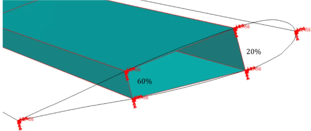
Here, 40 points are generated for each upper and lower cambers. These points are then splined to create the profile contour. The front spar was set at 20% of chord length, and the rear spar at 60%. Accordingly, the Wing-Box represents so 40% of chord length in each section of the wing.
Figure 4 - Wing-Box spars located at 20% and 60% of local chord. The wing is obtained by homothetically sweeping the Naca profil along the wing length.
2.2 Material, Meshing and Load cases for automating the sizing process
Material properties. The materials adopted in this study are the same usually found
in metallic single aisle aircrafts. Aluminium alloys Al 7150 T7751 and Al 2024 T351 Bare are chosen, with homogeneous and isotropic properties, so Young’s modulus (E), Poisson ratio (ν) and density (ρ) are the 3 parameters that matters - the Shear modulus G is computed directly from the equation E = 2·(1+ν)/G.
60%
The Al 7150 T7751 is used in the upper WB skin, upper corners stiffeners and upper WB skin stringers. The Al 2024 T351 Bare is used in the lower WB skin, lower corners stiffeners, lower WB skin stringers, front spar, rear spar and ribs. The properties are:
Al 7150 T7751: E = 71.016 GPa, ν = 0.3 and ρ = 2823 Kg/m3. Al 2024 T351 Bare: E = 73.774 GPa, ν = 0.3 and ρ = 2768 Kg/m3.
Element properties. Buckling, shear and bending stresses are important to be
analysed when studying a WB. So, for the skin, spars and ribs the 2D property Shell was chosen, which is translated in Nastran as a PSHELL card that defines the membrane, bending, transverse shear, and coupling properties of thin shell elements. The only geometric parameter is thickness, which will also be the optimization variable for Sol200. For stiffeners 1D beam elements were chosen.
Boundary conditions and load cases. Since we study WB as a cantilever wing that
is therefore fixed on the fuselage, all translational and rotational degrees of freedom are restricted at the wing root. Regarding the load cases, just a few are relevant for the preliminary design. The manoeuvre in altitude with the MTOW and cruise speed will be the only load case considered since it is the most critical load case when designing the wing structure - other important cases are landing and crash. While keeping the MTOW, we decided to consider empty fuel wings because fuel alleviates the bending moment, so disregarding its presence provides an even more critical situation. Minimum thickness constraint will also be taken into account since industrial technologic limitations exist and must not be ignored.
In this study, cruise Mach is 0.79, cruise altitude is 12500 meters (41000 ft) and ISA atmospheric conditions are assumed. For manoeuver in altitude, the critical load factor is considered to be nz = 2.5 and the security factor is 1.5, so the extreme load factor according to FAR25.303 is nzce = 3.75. Moreover, the shear center (SC) was chosen to express the mechanical actions of all forces and moments, what requires replacing the inertial forces that are applied at the gravity center (GC) and the aerodynamic forces that are applied on the aerodynamic center to the SC, by the equivalent systems of loads and moments. This allows then to resume all vertical forces to just one resultant, as well as for all bending moments and all torsion moments. Since drag is usually less than 1/17 of the aerodynamic lift, it is disregarded in this analysis, so no horizontal force is presented.
The explicit mathematical expressions and physical description of the considered loads can be found in [12- Elodie Roux] and so just their final formulas are reminded in this section. These loads are defined within a non-dimensional framework with lineic distributions, which are functions of the normalized coordinate measured along the considered wing spanwise
. (1)
Here y represents the distance measured from the leading edge of the wing root which is normalized by the half wingspan, while b denotes the wingspan.
The resultants of the shear, bending and torsion loads that are applied on the SC of each Rib at Y position are then described as combinations of aerodynamic and inertial contributions:
. (2) Here the distributions of shear force Sa, bending moment Ba and torsion Ta that correspond to the aerodynamic load are taken into account as follows. First the lift is then approximated to an elliptical distribution so that the total lift is equal to the weight times the extreme load factor nzce like:
(3)
with the wing area S, the (fluid?) mass density ρ, the aerodynamic speed Va, the lift coefficient Cz, and the gravity g. Then the shear efforts and bending moment are derived from an elliptical distribution, while the torsion comes out as a consequence of the profile moment coefficient Cmprofil , like
(4)
(5)
(6) where ε represents the profile maximum relative thickness. Regarding the related distributions of inertial and engine loads, since the engine mass and thrust are considered as important, their expressions depend on the location of Y with respect to the engine position Ym like:
(7)
(8)
(9) Here the last term of each Eq. (7)-(9) has two values: the first one is for Y before the engine position Ym, and the second for Y greater than Ym.
For aircrafts with wing mounted engines, the usual Ym position is notably at 1/3 of half wing span. Since the studied wing has 29 ribs equally spaced, the 10th rib was chosen to fix the nacelle and support the engine. The location of engine center of thrust is so set, vertically, at dF = 1.30 meters below the wing SC and, horizontally, at dM = 3.43 meters in front of the SC and its mass causes then local torsion and bending. Besides another important point that is considered in Eqs. (7)-(9) is the fuel distribution along wingspan. That one is also considered to be elliptical, although in the end zero fuel is admitted. Lately, Eqs. (7)-(9) furthermore involve the length lCG_CS is the distance between the GC and the SC, while Cr is the root cord length.
Meshing. For the meshing of the WB, a convergence study was made to have the
lightest mesh. In optimization problems, increasing mesh refinement usually results in a much harder computational work, but a coarse mesh also prevents good results. In the optimization process in Sol200 [22], analytical buckling formulas are implemented so we can use coarse mesh for panels. In this way, each spar section has only one element, and each skin section has 15 elements - defined by the 2 stiffeners and 14 stringers. For the 1D bar property, the Nastran translation for elements is CBAR. For the 2D shell, a Quad is the element shape, IsoMesh is the chosen mesher and Quad4 in the topology configuration. This means that all spars and skin elements are rectangles with the edge length controlled by the mesh seed. Nastran translates this by CQUAD4 elements that define an isoparametric membrane-bending or plane strain quadrilateral plate element. The ribs are meshed by paver that means irregular trapezoidal shapes.
Design parameters. Every parameterization, even for the mesh, is extremely
important since every studied wing has a completely different geometry (only dimensional parameters are kept constant). Changing the geometry parameters affects the local structural details (4 main input parameters change as well as hundreds of secondary parameters). About the properties, each section has 4 defined different skin thickness and 4 stringers and stiffeners geometrically correlated radius, and since there are 28 sections, at least 112 thickness are inputs that changes in every wing. With this amount of variables (denoted at Eq.12), a not all parameterized wing would cost and inestimable time spend in Patran, something absolutely not desirable.
3 Structural optimization
3.1 Structural sizing using surrogate model
The surrogate or response surface model is a reduced order tool that can replace a task that is taking too long time. In other words, if a process has inputs xi, a complex simulation and the output variables yout, an alternative is to approximate this fragment with a surrogate design. If it is well designed, it can run a lot of times very fast.
Through a MATLAB code, the response surface for the analytical results of the WB is made using recipes of the classical literature [21]. First, the bounds are fixed for each parameter:
i. Maximum thickness: 10 to 40 % of the chord length ii. Section: 2 to 28
iii. Maximum camber: 2 to 6 % of the chord length
For the construction of the surrogates we choose to use a Box-Behnken’s design [23] composed of 15 experiences. The output function , , is defined as follows with respect to the input variables x
the coefficients Bi being described in the table 1.
Table 1 - Reduced Model Coefficients for each part of the WB
Upper Skin Lower Skin Front Spar Rear Spar
B0 8.220 40.092 4.132 4.709 B1 -0.109 -2.494 -0.077 -0.088 B2 -0.170 -1.545 -0.066 -0.072 B3 -0.481 8.052 -0.136 -0.170 B4 0.002 0.052 0.001 0.001 B5 0.004 -0.202 0.001 0.001 B6 0.008 -0.055 0.002 0.003 B7 0.001 0.037 0.001 0.001 B8 -0.002 -0.005 -0.001 -0.002 B9 0.015 -0.016 0.006 0.007
Table 2 provides the root mean square error (RMSE). It is clearly evident from this table that the lower skin prediction has low worth beyond the others surrogates.
Table 2 - Root Mean Square Error of each part of the WB
Upper Skin Lower Skin Front Spar Rear Spar
RMSE 0.1146 6.0291 0.103 0.0926
As a result, poor results are acquired for the lower skin. In order to find the reason for that, the analytical approach section shows that the distribution of thickness in the wing for the lower skin is more unpredictable and also has a great difference between the maximum and minimum value of thickness. Moreover, the lower skin distribution of thickness changes a lot for each airfoil, which turns the modeling more complicated than the others.
Consequently, from now on, the parts of the WB analyzed are just the upper skin, front spar and rear spar. Actually, the elimination of the lower skin is not so important because, in the industry, the lower skin is not usually dimensioned with stress criteria, but with fatigue criteria as the main factor.
The building simplicity of the RSM with only one surrogate for each part of the WB comes at the expense of the precision for some portions, what is far from being reasonable. This problem that is related to the presence of the engine can be circumvented by using more than one surrogate at once for some specific portions. More specifically, for the upper skin response surface, it is probably enough to make 2 surrogates, but for the front and rear spar, it is natural to build up a surrogate before the engine position, another one between the engine position and the 25th section, and the third after the 25th section. Fig. 5 shows the relative error obtained for the upper skin surrogate model while making 2 types of response surfaces. Notably a full quadratic regression function is used for the 20 first sections, while a linear regression function is used for the 8 last sections.
Figure 5 - Relative Error for the Upper Skin with 2 surrogate models
Comparison of this result with the previous upper skin response surface has shown that this one has lower relative errors. This indicates that the choice of design space directly affects the quality of answers, and that, for this case, is better to separate into two design spaces and build up two surrogate models for the upper skin.
3.2 FEA with Nastran Sol200
The proposed analysis is based on a static load, and the main objective is to optimize the entire WB according to buckling and maximum shear stress criteria (see Fig. 6), strain criterion and maximum wing tip displacement. With a cantilever wing, given the load case, it is possible to calculate the minimum thickness for each part respecting the structural constraints. A global optimization will find the best thickness combination that will reduce the WB weight to a global minimum.
Figure 6 - Stress tensor in Static Solution using NACA 2420 profile - buckling response. ‐20 ‐15 ‐10 ‐5 0 5 10 15 0 5 10 15 20 25 30 Relative Error [%] Section 2415 2420 2520 2620 3415 4415 4420 4430
4 Numerical comparison
4.1 Sol200 versus surrogate
In order to better explore the optimization capabilities, a deeper study was performed on one WB only. The chosen profile is the NACA 2420. In our optimization process we distinguished the two following parts in order to initialize the design variables around an optimum: 1) solution based on the Reduced Model properties input, which means the Wing-Box based on the input parameters, without any optimization; 2) optimization in Sol200 is then performed using stress criteria fed by the response of the analytical reduced model.
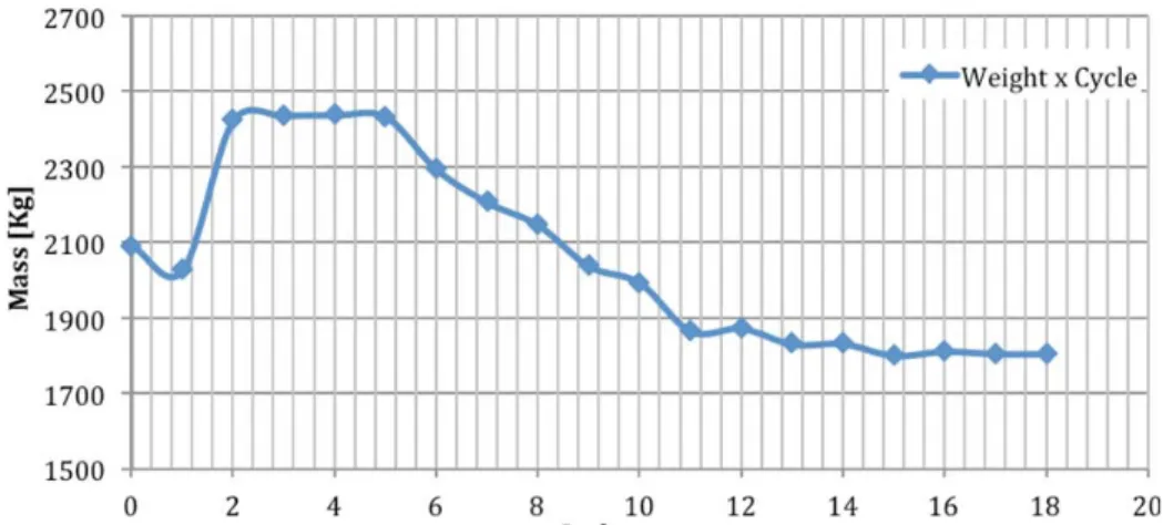
To get an idea of the computational cost, the structural optimisation (leading to the minimum global weight under constraints) involves 112 thickness variables. The other 112 variables (stringers and stiffeners) were also redefined accordingly to the area relations that define its dependency to the thickness variables. For the NACA 2420, optimization took 18 cycles to converge, and the mass reduction can be seen on the picture below.
Figure 7 - Mass optimization for NACA 4420 profile WB, Static Analysis optimized by Sol200 with stress criterion only, 18 cycles total.
After the 18 cycles, the results converge to a weight of 1805.88 Kg, which is a total reduction of 13.7% or 286 Kg on each semi-wing, a considerable amount in terms of aeronautics. Just to have an idea, the total weight reduction of 572 Kg is more than the total crew weight specified by FAR Part 25, for this class of transport aircraft (A320 and Boeing 737-800). Now the optimization results will be presented for each of the four aimed parts: Front Spar, Rear Spar, Upper WB Skin and Lower WB Skin. Each part presents 28 sections (series on the legend), and for each one the thickness optimization for each section will be presented (for the 18 cycles) and also the final thickness along span, before and after optimization (see example of optimisation of front spar on figure 8).
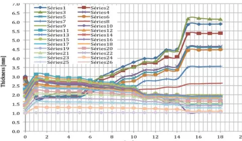
Figure 8 - Front Spar thickness optimization for the 28 sections in Sol200 with stress criterion only for NACA 2420 profile WB, in Static Analysis, 18 cycles total.
For the front spar, thickness decreases up to the 10th section, just before the engine. From the 11th section to the 17th it increases again and then decreases to the minimum thickness. Globally it is visible that the optimization increased the thickness distribution before the 10th rib, showing that the engine affects greatly the front spar, being decisive when designing this part of the Wing-Box.
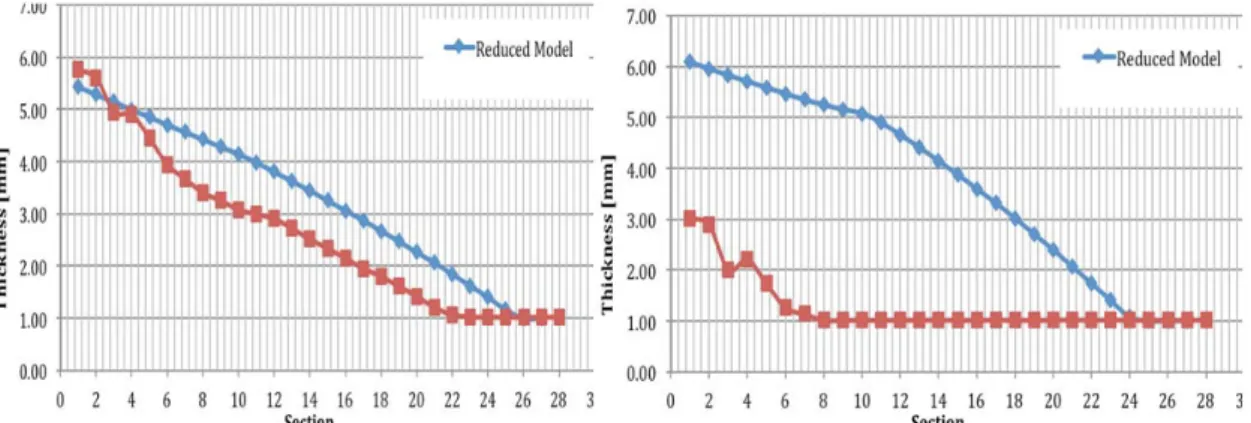
Figure 9- Front Spar and rear spar thickness before and after optimization in Sol200 for the 28 sections with stress criterion only for NACA 2420 profile WB, in Static Analysis.
For the rear spar, on other hand, optimization increases strongly the thickness of every section up to the 25th. The first 4 sections has even an increase of thickness by the order of 10 times, showing that in terms of a globally optimized structure, the rear spar is not well designed by the analytical model. It is important to remember that the numerical solution considers the interaction between all elements of the model, and so the response may be extremely different than expected. After optimization, the rear spar is totally different than the initial structure, but still the engine influences the design process, since greater thickness increment can be found before the 10th rib.
Figure 10 - Upper and lower WB thickness before and after optimization in Sol200 for the 28 sections with stress criterion only for NACA 2420 profile WB, in Static Analysis.
The behavior of the upper WB skin is completely different from the spars. In fact the optimization does not change much the section thickness, and the final results follow not by far the initial design. But in this case, the overall thickness decreases, and the engine influence is not visible. Almost 30% of the upper WB skin rests with the minimum 1,00mm thickness. Finally, for the lower WB skin, optimization decreases hugely the overall thickness, and 70% of all sections receive minimum thickness. It is visible that after the optimization, the importance of the lower skin is minimized when considering only stress as criterion, and that is why industry such as Airbus uses fatigue as main design criteria for this structure, instead of stress.
The maximum vertical wing tip displacement is now 0.412 meters, 77% less than for the non-optimized wing. This reflects the importance of optimization since, in the end, a lighter Wing-Box was generated, with better distributed stress along span, maximum stress respecting the material constraints and a maximum displacement reduced significantly, as may be desirable by aerodynamic constraints. Actually, the maximum displacement criterion isn’t usually active when designing a wing, and exists just for a critical reason.
4.2 RSM solution for CFD/CSM coupling
In this part, more general results for NACA 2415, 3415, 4415, 2420, 2520, 2620, 4420 and 4430 are presented, using the same optimization method as for Part II. The table 3 below presents the final weight for each of the 8 studied WB
Table 3 - Mass optimization in Sol200 for the 8 studied WB with different NACA profiles with stress criterion only in Static Analysis.
NACA 2415 3415 4415 2420 2520 2620 4420 4430 Wing Semi-Span [m] 38,3 34,2 31,2 38,3 37,4 36,2 31,2 31,2 Initial Mass [Kg] 2361,4 2148,0 2124,0 2091,8 2001,1 1883,8 1641,2 1407,5 Final Mass [Kg] 1551,9 1343,0 1096,2 1805,9 1729,0 1620,0 1244,3 1510,9 Reduction [%] -34,3 -37,5 -48,4 -13,7 -13,6 -14,0 -24,2 7,3
The quadratic mean of mass reduction for the 8 studied NACA profile is 26%, which is a great result since aeronautical industry searches the weight minimization at all costs.
As an exception for NACA 4430, the optimizations of the seven other models follow the weight order. That means the wings before and after optimization keep the same position in terms of final mass. Since all WB were design for corresponding wing with the same total lift coefficient, it is visible that the NACA 4420 is the best chosen wing when considering lift/weight. In fact, the profile NACA 4420 has a good thickness ratio and a considerable maximum camber, being very similar to the profiles uses in commercial aircrafts (e.g. Airbus A320 wing uses a variation of NACA 4412 profile).
It is also possible to see that increasing the maximum camber position in NACA 2X20 series decreases the weight, and the same when increasing the maximum camber in NACA X415 series. That explains in parts why NACA 44XX is the best choice for this type of aircraft, since both maximum camber and maximum camber position are high enough and almost at the limit of NACA 4-Digits Series equations.
5 Conclusion
This work presented a wing optimization process combining analytical surrogate model with FEA. The parametric model approach for structural optimization of a flexible wing, together with surrogate models, was found as a useful tool for the preliminary design of wing-boxes, helping the preliminary design task to achieve the optimized structure in the shortest time, enhancing the results by the lowest costs possible.
From the optimization process in Sol200, it was visible that the stress criterion is not a good choice when designing the lower WB skin, remembering why industry uses fatigue as main design criteria for this part. After the optimization, the importance of upper and lower skins was minimized and almost all efforts were concentrated on spars, specially the rear spar. Our numerical simulations have shown that NACA 44XX is the best choice for this type of aircraft, since both maximum camber and maximum camber position are high enough and almost at the limit of NACA 4-Digits Series equations. This will lead to further works dealing with NACA 5-Digits profiles involving more design variables and also increasing the complexity in the structural optimization process.
The next step is to associate this work with an aerodynamic approach using CFD, by optimizing the structure according to its aero response. Indeed, when operating in cruise, the deformed wing may request a new shape for the best efficiency. The coupling approach allows to create a variation of the required profile to construct the real wing that, when deformed, would assume its best shape in terms of aerodynamics, still respecting all structural constraints and minimum weight possible. The way to couple the two CSM and CFD physics is to allow a discussion between two surrogates of complex high performance models. This would be done by minimizing the difference between their optimization criteria which is, for static aero-elasticity, by mean of equivalent stiffness matrices for the flexible wing.
Another important perspective is to perform the same study with composite materials. The optimization of composite plates and shells, although, requests a much greater computational effort, since thickness is no longer the only variable, but also the number of layer and its orientation. Ultimately, the OSYCAF project aims at designing the flexible beams using multiphysics approach coupling with robustness analysis.
Acknowledgments
This work is a part of the scientific project OSYCAF (Optimisation d'un SYstème Couplé fluide-structure représentant une Aile Flexible) funded by the foundation STAE Toulouse (Sciences et Technologies pour l’Aéronautique et l’Espace). The authors gratefully acknowledge support from the foundation STAE.
References
[1] P. Piperni, M. Abdo, F. Kafyeke, “The development of a multi-disciplinary wing design method”, in: 2003 World Aviation Congress, Montreal, September 2003, SAE paper 2003-01-3023.
[2] M. Abdo, P. Piperni, A.T. Isikveren, F. Kafyeke, “Optimization of business jet”, in: CASI & Canadian Aeronautics Annual General Meeting. Aircraft design & Development Symposium, 2005.
[3] I. Kroo, V. Manning, “Collaborative optimization: status and directions”, AIAA paper, AIAA-2000-4721, pp. 1-11, 2000.
[4] I. Sobieski I. Kroo, “Collaborative optimization: using response surface estimation”, 36th Aerospace Sciences Meeting and Exhibit, AIAA-98-0915, pp. 1-12, January 1998.
[5] S. Allwright, “Technical data management for collaborative multi-discipline optimization”, AIAA paper, AIAA-96-4160, 1996.
[6] A. Gazaix, P. Gendre, E. Chaput, , C. Blondeau et al., "Investigation of Multi-Disciplinary Optimisation for Aircraft Preliminary Design," SAE Technical Paper 2011-01-2761, doi:10.4271/2011-01-2761, 2011.
[7] A. Forrester, A. Soberster, A. Keane. “Engineering Design via Surrogate Modeling”. UK, 2008.
[8] Y. Liang_X.-Q. Cheng, Z.-N. Li, J.-W. Xiang, “Robust multi-objective wing desing optimization via CFD approximation model”, Vol. 5, No. 2, pp. 286-300, 2011.
[9] L.R. Jenckinson, J.F. III Marchman, “Aircraft Design Projects for engineering students”, Butterworth Heinemann, 2003.
[10] F. Hurlimann, “Mass Estimation of Transport Aircraft Wing-Box Structures with a CAD/CAE - Based Multidisciplinary Process”, ETH Zurich, Diss ETH No 19458, 2010.
[11] G. Shi, G. Renaud, X. Yang, F. Zhang, S. Chen, “Integrated Wing Design with Three Disciplines”. AIAA 2002-5405, September 2002.
[12] S. A. Mostafa, A. Singh; R. Sedaghati. “Conceptual Design Optimization of an Aircraft Wing-Box Structure and Generating a High Fidelity Stick Model”. DMIE Concordia University, Report 6, 2007.
[13] H. Syamsudin. “Development of an Approach and Tool to Improve the Conceptual-Design Process of Wing Box Structure of Low-Subsonic Transport Aircraft”. PhD Thesis. Cranfield, UK, 2009.
[14] F. Luraghi, “Surrogate-Based Shape Optimization of Fiber Paths in Tow-Steered Laminates for Maximum Buckling Load”, 16th International Conference on Composite Structures, June 28-30, 2011, Porto, Portugal.
[15] N. Bartoli, D. Bettebghor, F. Luraghi, and M. Samuelides, “Surrogate Model-Based Design Optimization of Composite Panels for Aeronautical Applications”, 15th Austrian-French-German Conference on Optimization, September 19–23, 2011, Toulouse, France.
[16] F. Luraghi, “Efficient Design Optimization of Tow-Placed Panels for Enhanced Load-Carrying Capabilities by Adaptive Metamodeling”, 53rd AIAA/ASME/ASCE/AHS/ASC Structures, Structural Dynamics and Materials Conference, April 23–26, 2012 , Honolulu, HW.
[17] T.H.G. Megson, “Aircraft Structures for engineering students”. Butterworth Heinemann, 3rd Edition, 1999.
[18] M.C.Y. Niu, “Airframe Structural Design”. 2nd Edition. California, USA, 1988.
[19] T.L. Lomax, “Structural Loads Analysis for Commercial Transport Aircraft/ Theory and Practice”. 1st Edition. Virginia, USA, 1996.
[20] M.D. Ardema, M.C. Chambers, A.P. Patron, A.S. Hahn, H. Miura, M.D. Moore. “Analytical Fuselage and Wing Weight Estimation of Transport Aircraft. California, USA, 1996.
[21] E. Roux, “Modèle de Masse Voilure Avions de transport civil pour une approche analytique de la Dynamique du Vol”. Intitut Supérieur de l’Aéronautique et de l’Espace - Supaero & ONERA, 2006.
[22] MSC. Software Corporation, “MD Nastran 2010 Design Sensitivity and Optimization User’s Guide”. 2010.
[23] George Box, Donald Behnken, “Some new three level designs for the study of quantitative variables”, Technometrics, Volume 2, pages 455–475, 1960.