HAL Id: hal-01963830
https://hal.sorbonne-universite.fr/hal-01963830
Submitted on 21 Oct 2019
HAL is a multi-disciplinary open access
archive for the deposit and dissemination of
sci-entific research documents, whether they are
pub-lished or not. The documents may come from
teaching and research institutions in France or
abroad, or from public or private research centers.
L’archive ouverte pluridisciplinaire HAL, est
destinée au dépôt et à la diffusion de documents
scientifiques de niveau recherche, publiés ou non,
émanant des établissements d’enseignement et de
recherche français ou étrangers, des laboratoires
publics ou privés.
Modeling and Virtual Prototyping for Embedded
Systems on Mixed-Signal Multicores
Rodrigo Cortés Porto, Daniela Genius, Ludovic Apvrille
To cite this version:
Rodrigo Cortés Porto, Daniela Genius, Ludovic Apvrille. Modeling and Virtual Prototyping for
Em-bedded Systems on Mixed-Signal Multicores. RAPIDO 2019 - 11th Workshop on Rapid Simulation
and Performance Evaluation, Jan 2019, Valencia, Spain. �10.1145/3300189.3300193�. �hal-01963830�
Mixed-Signal Multicores
Rodrigo Cortés Porto
Technische Universität Kaiserslautern, Germany
LIP6 - Sorbonne Université Paris, France
Daniela Genius
LIP6 - Sorbonne Université Paris, France
Ludovic Apvrille
LTCI - Télécom ParisTech Université Paris Saclay, France
ABSTRACT
This paper presents a tool for the virtual prototyping of analog and mixed-signal embedded (AMS) systems. The application and plat-form are modeled on a high (SysML-like) level, while the prototype is simulated on cycle-bit accurate level. In order to run software, we combine the AMS part with a multicore platform, which acts as initiator and controls the AMS part. The synchronization between these different Models of Computation (MoC) can be validated be-fore the generation of the virtual prototype. We present a larger case study to illustrate our approach.
ACM Reference Format:
Rodrigo Cortés Porto, Daniela Genius, and Ludovic Apvrille. 2018. Modeling and Virtual Prototyping for Embedded Systems on Mixed-Signal Multicores. InProceedings of Workshop (RAPIDO’19). ACM, New York, NY, USA, 7 pages. https://doi.org/10.1145/nnnnnnn.nnnnnnn
1
INTRODUCTION
Due to the high complexity of today’s embedded systems, model-driven development techniques are a usual practice for the design and development of embedded software. These techniques rely on high level models to create a software architecture, behavior and allocation, and then perform model transformations to generate software executable code.
These approaches are however generally limited to the digital parts of the system. Yet, embedded systems are often composed of digital and analog—analog/mixed signal (AMS) and radio frequency (RF)—components. Typical examples are found in domains such as IoTs, robotics, avionics, medical and automotive.
In very early design phases, fast (but less precise) allocation exploration can be used. Assumptions and results of verifications performed at a high level of abstraction need to be cross-checked once models have been refined. To support this multi-level process, heterogeneous embedded systems may require a high-level repre-sentation including models for both AMS and RF components but also very precise simulations techniques for late validations. Last but not least, the possibility to execute software on digital parts is required as soon as possible in the design process.
Permission to make digital or hard copies of part or all of this work for personal or classroom use is granted without fee provided that copies are not made or distributed for profit or commercial advantage and that copies bear this notice and the full citation on the first page. Copyrights for third-party components of this work must be honored. For all other uses, contact the owner /author(s).
RAPIDO’19, January 2019, Valencia, Spain © 2018 Copyright held by the owner/author(s). ACM ISBN 978-x-xxxx-xxxx-x/YY/MM. https://doi.org/10.1145/nnnnnnn.nnnnnnn
This paper presents the integration of analog components into a modeling and virtual prototyping framework. The synchronization between the different Models of Computations (MoC) is performed before a virtual prototype is generated from models. The cycle-bit accurate prototyping environment can be used to feed back simulation results to higher modeling levels in order to check the taken assumptions e.g. on cache miss rate or memory access latency. Our contribution adds analog components as targets in a MPSoC built upon general purpose CP Us running a (light) operating system and the application code.
The related work in the next section demonstrates the lack of an integrated tool offering both mixed-signal system modeling and precise simulation capabilities, as well as the possibility to run application code.
The following section presents the foundations of the present work: SystemC AMS extensions —in particular its Timed Data Flow (TDF) model of computation— and a high-level modeling and virtual prototyping tool named T Tool. Our mdoeling extensions aare then presented using relevant systems with an important proportion of analog components.
2
RELATED WORK
Well established tools likePtolemy II [? ][? ] target data-flow mod-els for heterogeneous systems by defining several sub domains [? ]. Although hierarchy is provided, instantiation of elements con-trolling the time synchronization between domains is left to the responsibility of designers.
Metropolis [? ] is based on high level models with a clear separa-tion between computasepara-tion and communicasepara-tion concerns. Heteroge-neous systems are taken into consideration, but heterogeneity can only be represented using processes, mediums, quantities and con-straints. Hierarchical models are not allowed: all processes should be implemented in the same hierarchical level.
Metro II [? ] introduces hierarchy and allows Adaptors for data synchronization as a bridge between the semantics of components belonging to different MoCs. The model designer must cope with the implementation of time synchronization by means of con-straints, assertions, annotators and schedulers. As a common sim-ulation kernel handles all process execution, MoCs are not well separated.
There are other frameworks based on SystemC such as HetSC [? ], HetMoC [? ] and ForSyDe [? ], all having the disadvantage that designers must handle the instantiation of elements and synchro-nization aspects.
In the scope of [? ], a mixed analog-digital systems proof-of-concept simulator has been developed [? ], based on the SystemC
RAPIDO’19, January 2019, Valencia, Spain R. Cortes Porto et al.
AMS extension standard [? ? ]. Another simulator is proposed in [? ]. Integration with software code for general-purpose CPUs and with an operating system is however not yet addressed in these approaches.
Outside the analog/mixed signal domain, UML/SysML based modeling techniques [? ? ] are popular with industry targeting embedded systems, but are still rarely used in the domain of hetero-geneous system design. Furthermore, with few exceptions such as [? ? ], they do not lower the level of abstraction to cycle bit accurate level.
3
CONTEXT
Our work is based on two foundations: the AMS extensions for SystemC and a high-level modeling and prototyping tool (T Tool)
3.1
SystemC Extensions for AMS
"SystemC AMS extensions" is a standard describing an extension of SystemC with AMS and RF features [? ][? ]. The usual approach for modeling the digital part of heterogeneous systems with SystemC [? ] is to rely on its Discrete Event (DE) simulation kernel. The Timed data Flow (TDF) model of computation (MoC) of SystemC AMS adds support for signals where data values are sampled with a constant time step. TheElectrical Linear Networks (ELN) MoC of SystemC AMS on the other hand relies on a continuous time domain.
A TDF module is described with an attribute representing the time step and a processing function. The time step is associated to a time period during which the processing function should be executed. Theprocessing() function corresponds to a mathematical function which depends on the module inputs and/or internal states. At each time step, a TDF module first reads a fixed number of samples from each of its input ports, then executes the processing function, and writes a fixed number of samples to each of its output ports. TDF modules can interact with the DE world (such as digital MPSoC platforms) using converter ports.
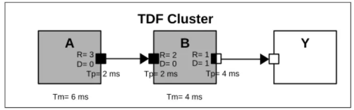
Figure 1 shows a TDF cluster, where the DE modules are repre-sented as white blocks, TDF modules as gray blocks, TDF normal ports as black squares, TDF converter ports as black and white squares, DE ports as white squares and TDF signals as arrows. The TDF modules of a cluster have the following attributes:
(1) Module Timestep (Tm) denotes the period during which the module will be activated. One module will be activated only if there are enough samples available at its input ports. (2) Rate (R). Each module will read or write a fixed number
of data samples each time it is activated. This number is annotated to the ports and it is known as theport rate. (3) Port Timestep (Tp) denotes the period during which each
port of a module will be activated. It also denotes the time interval between two samples that are being read or written. (4) Delay (D). A delay can be assigned to a port. As its name suggests, this attribute will make the port to handle a fixed number of samples each time it is activated, and read or write them in the following activation of the port.
Despite of all these features, [? ] explains that it is hard to build a modeling environment synchronizing DE and TDF. Indeed, the TDF model of computation is based on the Synchronous Data Flow (SDF)
A B Y R= 1 D= 1 Tm= 6 ms Tm= 4 ms Tp= 4 ms R= 3 Tp= 2 ms D= 0 R= 2D= 0 Tp= 2 ms TDF Cluster Figure 1: TDF Cluster
formalism that considers models as a network of synchronous data flow blocks, and does not easily match the one of DE systems. Thus, when there are interactions between the TDF and DE models of computation, time synchronization may induce causality problems. A TDF module is connected to a DE module through converter ports. When the TDF module accesses its input converter port, the DE simulation time advances until it is equal to the TDF simulation time of the input converter port. If later an access to an output converter port occurs whose TDF simulation time is less than the new DE simulation time, a time synchronization issue will occur: the TDF simulation time of the output converter ports needs to be always greater or equal than the DE simulation time.
In the work mentioned above, this synchronization is modeled with the help of colored timed Petri Nets derived from the SystemC AMS code. Causality issues between TDF and DE MoC are then automatically checked.
3.2
TTool
T Tool [? ] is a SysML based, free and open-source software ini-tially conceived for model-based engineering of (digital) embedded systems at different abstraction levels: functional, partitioning, soft-ware design and deployment. The method associated to these levels [? ] details how to take hardware/software partitioning decisions at a high level of abstraction and to regularly (re)validate these decisions during software development. Software tasks for the par-titioning model are captured within the functional abstraction level, and software tasks used in deployments are captured in the soft-ware design abstraction level. In both partitioning and deployment models, the computation part of tasks is allocated to processors (which can be hardware accelerators in the partitioning level), and the communication and storage part is allocated to buses and memo-ries. An important advantage of T Tool is that it offers an automated approach for formal verification and fast simulation for the digital part. Formal verification is based on internal model-checkers, or on external tools like UPPAAL [? ].
From deployment diagrams, T Tool can generate a virtual proto-type that can be simulated with a cycle bit accurate simulator for Multi Processor Systems on Chip (MPSoC) [? ]. Processor models stem from theSoCLib [? ] public domain library written in SystemC. SoCLib targets shared-memorymultiprocessor-on-chip system archi-tectures based on theVirtual Component Interconnect [? ] standard which separates the components’ functionality from their commu-nication. Software code is cross-compiled for a general purpose processor and runs under a micro kernel on the digital MPSoC.
However, while sensors, GPS, radar, etc. can be approximately modeled with highly abstracted digital blocks, the accuracy and
verification would benefit from more realistic models taking into account the AMS part.
4
INTEGRATION OF ANALOG COMPONENTS
INTO TTOOL
For the analog part, we focus on the Timed Data Flow (TDF) Model of Computation (MoC) which is based on the timeless Synchronous Data Flow (SDF) [? ]. So-called converter ports serve as interface between the TDF and DE MoC, raising potential causality issues.
4.1
Representing Analog Components
The graphical interface of T Tool has been extended by SystemC AMS DE and TDF blocks. Analog and digital parts are designed on different views. Also, there is one view per TDF cluster.
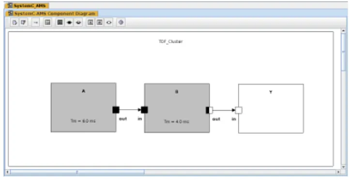
Figure 2: Extension of TTool: SystemC-AMS Diagram
Figure 2 shows a panel for the design of the introductory example. Each TDF cluster is designed in its own panel (or view) using a dedicated toolbar.
When a TDF module is created, it is possible to modify its at-tributes and parameters e.g. the name and Timestep or Period (Tm) of a module can be defined and time resolution selected. The pa-rameters of a TDF module such as its internal variables or template parameters can be also set up, as shown in Figure 3.
Analog components are difficult to parameterize since they are specifically designed for one given purpose. We thus decided to pro-vide a specific dialog window where SystemC-AMSprocessing() functions can be entered, e.g. see Figure 4.
From these diagrams, we can generate SystemC AMS TDF code of the components, the top cells of the mixed graphical/textual descriptions, and a Makefile.
4.2
Connecting AMS Components to the
MPSoC
SoCLib is based on the shared memory paradigm, where compo-nents are interconnected based on the VCI [? ] protocol. These components can be initiators which issue requests (e.g. CP Us) and targets that respond to these requests (e.g. RAM memory). The main idea for the integration of SystemC-AMS and SoCLib compo-nents into T Tool is that the analog compocompo-nents will act astargets for the SoCLib initiator digital components (CP Us, hardware ac-celerators, DMA, . . . ). The generated topcell is thus composed of SoCLib modules and interfaces to the SystemC-AMS clusters. It
Figure 3: TDF module parameters
Figure 4: TDF module process code
is also important to mention that a TDF cluster may contain DE modules which are not part of the SoCLib library.
GPIO2VCI p_rdata_ams p_wdata_ams TDF_Module p_clk p_resetn p_vci VCI_Bus TDF Cluster SoCLib DE Components
Figure 5: GPIO2VCI component
Our solution is to propose a new generic adaptor module as an interface between the SystemC-AMS modules and the the SoCLib interconnect components. This adaptor is modeled as a general-purpose input/output (GPIO) adaptor to VCI. We called itGPIO2VCI.
RAPIDO’19, January 2019, Valencia, Spain R. Cortes Porto et al. SRC SENSOR CTRL Rout = 1 Dout = 0 TmADC = 10us Rout = 1 Dout = 0 in out out in x_sig RDin in = 1= 0 v_sig PGA Rin = 1 Din = 0 Rout = 1 Dout = 0 Rkin = 1 Dkin = 0 vamp_sig ADC Rin = 10 Din = 0 TDF2DE Rin = 1 Din = 0 Rout = 1 Dout in adc_sig AAVG Rclk = 1 Dclk Rin = 64 Din = 0 amp in out kin k_sig in R out = 1 Dout = 0 out out Ramp = 1 Damp clk amp_sig clk_sig clk in out out_sig
Figure 6: Vibration sensor model from [? ]
It fulfills the rules for writing cycle-bit precise SystemC simulation models of SoCLib. Figure 5 shows the model of this component and how it works as an interface between the SystemC-AMS modules (TDF_Module belonging to a TDF Cluster) and the SoCLib VCI interconnect component (VCI_Bus). The component is manually inserted in the graphical interface of the panel, then its instantiation and connection, in particular the required lines in the topcell, are automatically generated.
5
CASE STUDY: VIBRATION SENSOR
The model of a vibration sensor, taken from the H-Inception project [? ], is shown in Figure 6. It consists of six TDF modules and one DE module.
decrease_gain keep_gain
increase_gain
low_threshold <= amp_sig < high_threshold
amp_sig < low_threshold amp_sig < high_threshold amp_sig >= high_threshold amp_sig >= high_threshold amp_sig < high_threshold amp_sig >= high_threshold
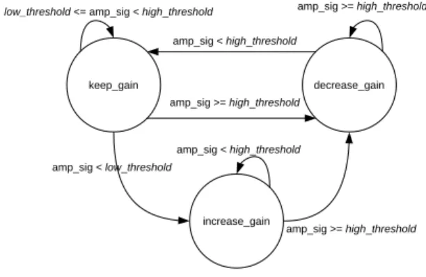
Figure 7: CTRL module state machine
TheSRC module represents the vibration source, modeled as a generator of harmonic sinusoidal waves which represent a dis-placement signal (x_sig) caused by the vibration.
TheSENSOR module represents a vibration sensor. It takes as input the displacement signal (x_sig) and yields a voltage signal (v_sig) which is proportional to the vibration velocity.
The programmable gain amplifier (PGA) amplifies the voltage input signal (v_sig) by a factor of 2ˆk, where k is the input value from signalk_sig. This signal is controlled by the gain controller DE moduleCTRL. It yields an amplified voltage signal vamp_sig. TheADC module represents an analog to digital converter with a resolution of 5 (Nbits). The ADC has a rate of 10 in its input port. Hence, it takes 10 samples from the amplified voltage signal vamp_sig and produces a digitized integer value of N-bits (adc_sig)
where the most significant bit corresponds to the sign. The Module-Timestep is assigned to this module as 10us.
TheTDF2DE module is a converter from the TDF signal adc_sig to a DE signalout_sig. The delay D_out, shown in red, of its output converter portout has not been set yet.
TheAAVG module represents an absolute amplitude averager. It calculates and outputs to theamp_sig the absolute average am-plitudes of the received samples from theadc_sig. Its input port has a rate of 64, meaning that it will receive 64 samples int oder to calculate the absolute average amplitude. This module also gen-erates a clock signalclk_sig at its output port clk, which has a rate of 2, meaning that a clock edge will be generated twice per activation of the module. Note that the delaysD_clk and D_amp, shown in red, of its output converter ports have not been set yet.
TheCTRL DE module represents the gain controller. This con-troller is modelled based on the state machine diagram shown in Figure 7. It controls the output signalk_sig based on the calcu-lated absolute average amplitude given byamp_sig, and two given thresholdslow_threshold and high_threshold.
5.1
Solving Causality Problems
The following algorithm detects causality issues and suggests how to fix them with extra delays. This algorithm is meant to be called before the generation of the virtual prototype.
1: procedure detectTimeSyncIssues 2: for each Module in Static Schedule do 3: for each Converter Port do 4: if Input Converter Port then 5: advancetDE
6: computemax_tDE
7: else if Output Converter Port then 8: computetTDFof port
9: if !(tTDF ≥max_tDE)then
10: Time synchronization issue detected
11: Suggest port delay to fix it
12: end if 13: end if 14: end for 15: end for 16: end procedure
Based on the static schedule for one complete TDF cluster pe-riod, each time a TDF module is executed, for each accessed input
Figure 8: Vibration sensor model in TTool
converter port, the DE simulation time (tDE) will advance as shown in line 5, and the maximumtDEwill be stored, as shown in line 6. Then, for each accessed output converter port, the TDF simulation time (tTDF) is computed on line 8. ThetTDFof each port should be greater than or equal to the maximum stored DE simulation time, as shown in line 9. If this condition fails, it means there is a causality problem with the time synchronization and a delay in the output converter port where the issue was detected will be suggested in order to solve the problem1.
For a first validation, the three output converter port delays shown in red (see Figure 6) were set to 0. The vibration sensor was modeled in T Tool, as shown in Figure 8. Figure 9 shows the output of the validation tab of the code generation window. As time synchronization issues are found, modifications for the three delays are suggested.
Figure 9: Code generation window with suggested delays For the output converter portout of theTDF2DE module, we use a delay equal to 1. For the output converter portamp of the AAVG module, the delay is equal to 1. Finally, 2 is used for the delay of the output converter portclk of the sameAAVG module. The vibration sensor model is already included in the SystemC-MDVP (Multi Domain Virtual Prototyping) simulator, developed 1
A more detailed version of the algorithm is shown in [? ].
in the context of [? ], as part of the model examples. The model was simulated without giving any delays to its output converter ports. As displayed, it also suggests the three same delays as the ones suggested by T Tool in order to solve the causality problems. Finally the SystemC-AMS model taken from [? ] was modified to include the same parameters as the ones used in T Tool and SystemC-MDVP, i.e. the same port rates and ADCNbits resolution. At first, the simulation was executed without assigning any delays to the output converter ports.
Synchronization issues are detected by the simulator each time the simulation runs, and delays referring to time units are suggested to solve the causality problems. First time the simulation was run, a delay of 9µs in port tdf2de.out was suggested, corresponding to a delay of 1 since the propagated timestep of this port is 10µs. After setting this delay, the simulation was run again; another syn-chronization problem was found, and a delay of 639µs is suggested to theaavg.clk port. Since the timestep of this port is of 320µs, a delay of 2 is needed. Finally, after setting this new delay, the simulation was run for the third time. This time, another causality problem was detected, and a delay of 639µs is suggested to the port aavg.amp. The timestep of this port is of 640µs, thus a delay of 1 is required.
All the delays suggested by the SystemC-AMS simulator are the same as the ones suggested by T Tool and the SystemC-MDVP simulator from [? ]. But on its side, TTool can identify causality problems before code generation and execution. In SystemC-MDVP, synchronization issues are found in the pre-simulation phase. That means that the SystemC-MDVP model needs to be executed only once to find any synchronization problems. In SystemC-AMS, these issues are found during the simulation phase, meaning that the sim-ulation needs to be executed once per identified causality problem. In our case study, it needed to be executed three times.
5.2
Simulation
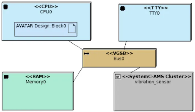
A simple SoC model was created as shown in Figure 10, where one SystemC-AMS Cluster block representing the vibration sensor was created, with trace file generation enabled. Such a model can potentially contain a larger number of processor cores, their number being limited only by the interconnect.
RAPIDO’19, January 2019, Valencia, Spain R. Cortes Porto et al.
Figure 10: Deployment Diagram model including the vibra-tion sensor TDF cluster
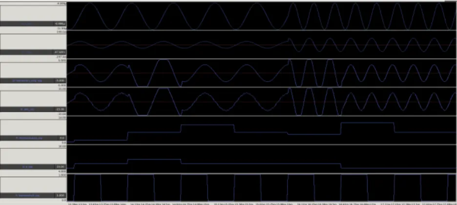
In order to compare the results of our approach with SystemC-AMS and SystemC-MDVP, simulations were run with the same delays and trace files with models signals were produced. Figure 11 shows the analog waveforms in blue, resulting from the simulation of the SystemC-AMS model. Figure 12 shows the analog waveforms in green, resulting from the simulation of the SystemC-MDVP model. Figure 13 shows the analog waveforms in red, resulting from the simulation of the SystemC model created from T Tool. It can be seen that the outputs match, specially for the fourth signal, which corresponds to the digitized output from theADC component. The first waveform corresponds to the signalx_sig which carries the output of the harmonic sinusoidal wavelets generatorSRC, simulating a vibration source. The second waveform is from the signalv_sig, which is the voltage output from the vibration sensor moduleSENSOR. The third waveform corresponds to the v_amp signal, which is the signal being amplified by thePGA module. The fourth signaladc_sig is the digitized output from the ADC module. The fifth signalamp_sig corresponds to the output of the absolute amplitude averagerAAVG module which is connected to the DE controllerCTRL. This controller emits the sixth signal k_sig which carries the factor that will be used by thePGA module to amplify the voltage signalv_sig. The last signal is the clk_sig used as clock signal for the controllerCTRL module. Note that the amp_sig and k_sig signals from the SystemC-MDVP simulation look different: this is due to the generated trace file that didn’t create values when they were repeated. So only the value changes are shown, but they still correspond to the outputs from the other traces.
This case study demonstrates that the solution implemented in T Tool to detect time synchronization issues yields the same results as the ones suggested by the SystemC-AMS and the SystemC-MDVP simulators. Moreover, the time synchronization issues detection is performed at the design level, before the virtual prototype or the software code are generated, thus giving the designer the possibility to adapt their design before simulation.
6
CONCLUSION AND PERSPECTIVES
We integrate SystemC-AMS (TDF) components into a High-level modeling tool for complex embedded systems and show how ap-plication code can be run in such systems by combining the AMS part with a prototype built out of SoCLib components. Contrary to
other approaches, we detect causality issues between the two parts of the simulation before any code is generated, which is one of the major strength of our approach.
To do so, we created a library to provide read and write func-tions to the GPIO2VCI component, which can be used in the State Machine Diagrams of T Tool. The AMS hardware components are considered to be targets inside the MPSoC platform. In the future, we suggest to authorize these components to act as initiators, or to support interrupts. Also, the static schedule computed by T Tool could be optimized, so that the suggested delays to solve time syn-chronization issues are minimum.
TheElectrical Linear Networks (ELN) model of computation of System-C AMS relies on a continuous time domain. We plan to push our studies further by integrating ELN into our tool.
Finally, even if analog components tend to be unique, for typical components such as filters, analog/digital converters, sine sources, we plan to provide a library of parametrizable building blocks.
Figure 11: Vibration sensor trace signal from SystemC-AMS simulation
Figure 12: Vibration sensor trace signal from SystemC-MDVP simulation