HAL Id: hal-00804199
https://hal.archives-ouvertes.fr/hal-00804199
Submitted on 25 Mar 2013HAL is a multi-disciplinary open access
archive for the deposit and dissemination of sci-entific research documents, whether they are pub-lished or not. The documents may come from teaching and research institutions in France or abroad, or from public or private research centers.
L’archive ouverte pluridisciplinaire HAL, est destinée au dépôt et à la diffusion de documents scientifiques de niveau recherche, publiés ou non, émanant des établissements d’enseignement et de recherche français ou étrangers, des laboratoires publics ou privés.
Functionalization control of porous silicon optical
structures using reflectance spectra modeling for
biosensing applications
Nathalie Lorrain, Mohamed Hiraoui, Mohammed Guendouz, Lazhar Haji
To cite this version:
Nathalie Lorrain, Mohamed Hiraoui, Mohammed Guendouz, Lazhar Haji. Functionalization control of porous silicon optical structures using reflectance spectra modeling for biosensing applications. Mate-rials Science and Engineering: B, Elsevier, 2011, 176 (14), pp.1047-1053. �10.1016/j.mseb.2011.05.040�. �hal-00804199�
Functionalization control of porous silicon optical structures using reflectance spectra modeling for biosensing applications
N. Lorrain1*, M. Hiraoui1, 2, M. Guendouz1 and L. Haji1
(1)
Université Européenne de Bretagne, CNRS-UMR 6082, BP 80518, ENSSAT 6 rue Kerampont, 22305 Lannion Cedex, France
(2)
Unité de Spectroscopie Raman, Faculté des Sciences de Tunis, 2092 El Manar-Tunisia.
* Corresponding author: nathalie.lorain@univ-rennes1.fr
Abstract
Modeling and experimental reflectance spectra of porous silicon single layers at different
steps of functionalization and protein grafting process are adjusted in order to determine the
volume fraction of the biomolecules attached to the internal pore surface. This method is
applied in order to control the efficiency of the chemical functionalization process of porous
silicon single layers. Using results from single porous silicon layer study, theoretical
microcavity is simulated at each step of the functionalization process. The calculated
reflectance spectrum is in good agreement to the experimental one. Therefore the single
layers study can be applied to multilayer structures and can be adapted for other optical
structures such as waveguides, interferometers for biosensing applications.
Keywords
1 Introduction
This last decade, porous silicon (PS) has become an attractive material which is widely used
in optical sensing applications for different targets such as gases, enzymes, proteins…due to
its large specific sensing area [1-5]. The most common technique used for the PS elaboration
is the electrochemical etching in aqueous hydrofluoric acid (HF) [6]. The electrochemical
conditions as well as the choice of the type and the resistivity of silicon substrate constitute
the key parameters which control the refractive index and the morphology of porous silicon
[6]. Indeed, the applied method allows the modulation of refractive index and pore size and
enables various optical devices such as waveguides [7], Bragg reflectors and microcavities
[8, 9] to be elaborated. In such optical structures, the incorporation of species in the pores
increases the refractive index of the medium. In particular, a microcavity is very sensitive to
refractive index variations. In fact, the attachment of biomolecules is detected by shifts in the
resonant wavelength [3].
Moreover, the pore size has to be large to allow efficient infiltration of biomolecules but small
enough to avoid light-scattering effects and to offer a large internal specific surface area. Such
a large internal PS surface is necessary in order to enable high quality detection of introduced
molecules [9-11].
Among many sensing application fields, PS is largely used as a good matrix for biosensors
thanks to its biocompatibility and its capacity to immobilize a large number of biomolecules
[3]. In freshly etched structures, the internal surface of PS is essentially constituted of SiH,
SiH2 and SiH3 groups [12]. This surface is hydrophobic and unstable for a use in aqueous
media. In order to stabilize the PS surface, it is oxidized by a heating treatment to obtain
to obtain the covalent attachment of reactive groups of silane. Finally, a coupling agent
between silane groups and biomolecules is required for the attachment of protein molecules
[13, 14].
In this paper, we focus on the control of PS functionalization for biomolecules detection using
reflectometry method. Glutaraldehyde molecule has been used as the coupling agent. Bovine
Serum Albumin (BSA) molecule has been used as the test biomolecule. This is one of the
most extensively protein studied [15] and is easily linked to Glutaraldehyde molecules by
covalent bend with a good stability [16].
We first present microstructural and optical characterizations of PS single layers. Using a
model, the spectral reflectance of PS single layers is calculated for two different anodization
conditions and is adjusted to the experimental one in order to determine the volume fractions
of the different constituents at each step of the functionalization process.
Then, we present the experimental results of a PS microcavity elaborated and functionalized
with the same conditions used in the studied single layers. Using the adjusted volume
fractions of each constituent obtained from the single layer study, we calculated the
theoretical reflectance spectra of the microcavity after each functionalization step and
compared them to the experimental ones.
2 Experimental
Porous silicon (PS) single layers and a microcavity have been prepared by anodization
process using P+ (100) silicon substrate with a 4-6 mΩ.cm-1 resistivity. The electrolyte was formed by combining hydrofluoric acid (50 %) with ethanol and deionised water (DIW) with
the ratio of 1:2:2 respectively. The anodization duration and the current density were
controlled by a programmable current source. Two types of PS layers have been studied using
densities have also been used to elaborate a microcavity with an alternation of 12 periods of H
and L layers for Bragg mirrors separated by the active layer (H).
In order to stabilize freshly etched structures and to prepare the PS surface for
attachment of biomolecules purposes, PS surfaces have been partially oxidized at 300°C for
one hour in wet O2. After this thermal treatment, the surface must be activated with silanol
groups. Firstly, partially oxidized porous silicon (POPS) samples were immersed in a 2 %
(3-Aminopropyl) triethoxysilane (APTES, from Sigma-Aldrich) and a hydro alcoholic mixture
of DIW and methanol (1:1) solution for 20 minutes at room temperature. Then, samples were
removed from the APTES solution and were rinsed in DI water. Finally, samples were dried
with N2 and heated at 100°C over 10 minutes to evacuate the solvent vapors.
In the second chemical functionalization step (Coupling step), the samples were impregnated
in 2.5 % solution of Glutaraldehyde (GL, from Sigma Aldrich) adjusted to pH 7 using NaOH
(0.5 mol.l-1) solution for one hour at room temperature. Then the samples were rinsed in DIW
in order to remove any excess of GL molecules and dried under N2 flow.
The last step consisted in incubating at room temperature the functionalized samples in a
solution of bovine serum albumine (BSA, from Sigma-Aldrich) for 2 days. The BSA solution
was prepared by dissolving 15 mg of BSA powder in 5 ml of DIW. After impregnation, the
samples were rinsed with DIW and dried under a steady nitrogen gas flow.
The reflectivity measurements have been performed before and after each functionalization
process using UV - VIS - PIR spectrometer (Ocean Optics HR 4000). All reflectance spectra
were obtained and investigated in the 800 - 1100 nm wavelength range at ambiant
temperature.
SEM cross sectional observations using HITACHI S-2500 have provided information on the
possible to estimate pore size distribution using an image analysis tool developed using
MATLAB software.
3 Modeling
In the present study, the calculations of the refractive index values and reflectance as a
function of wavelength were carried out using a MATLAB program. The matrix transfer
method [17] has been applied to calculate reflectance spectra of a PS single layer and a PS
microcavity after each elaboration and functionalization step. The thickness of each layer is
fixed and obtained from the SEM cross section measurements. To obtain the reflectance
spectra, the refractive index of the two different layers and their constituents must be defined
as a function of λ. For silicon or silica, the variation of refractive index values for an intrinsic material has been taken into consideration [18]. For APTES, GL and BSA molecules, we have
considered constant refractive indexes which are respectively equal to 1.42, 1.43 and 1.445
[19]. In order to determine the refractive index of the studied layers, we have used the
Bruggemann model [20] which relates the refractive index ni of the constituent i to its volume
fraction Ci in an effective medium composed of i constituent:
1
= + − i i i i n n n n C 0 2 2 2 2 2 (1) with1
= i i C 1 (2)Where ni and n are the refractive index of the constituent i and the effective medium
respectively.
If the ni(λ) and the Ci are known for each constituent i in each layer, the refractive index n of
each layer can be then calculated as a function of λ.
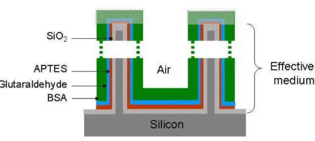
In our case, each layer is constituted by a network of partially oxidized silicon crystallites
separated by pores, the surface of which has been covered by APTES, GL and BSA protein
attached to the top crystallite surface (hatched area in figure 1). Thus, the effective medium is
almost composed of silicon, air, silica, APTES, GL and BSA molecules and is delimited by
air and silicon substrate.
Figure 1: Schematic of a functionalized partially oxidized PS layer. The volume fraction of molecules which is deposited on the top partially oxidized silicon crystallites surface is not taken into consideration in the model of refractive index estimation.
The method of determining the refractive index of PS single layers has been based on the
adjustment of the experimental reflectance spectra with the theoretical ones for each
elaboration and functionalization step: only one parameter is then unknown which is the
volume fraction of the constituent i added at the step i. This parameter was initially arbitrarily
fixed in order to calculate the refractive index n, and then the reflectance R for each λ was deduced. The parameter was then varied in order to adjust the experimental with the
calculated reflectance spectra. The volume fraction of the constituent i was equal to the
The method used for obtaining an estimation of the refractive index and applied at each step is
detailed as follows.
- Step 1, as-prepared PS layer:
After the PS formation step, the constituents of the layer delimited by air and silicon
substrate are the silicon (volume fraction CSi_1) and air (volume fraction Cair_1: porosity). By
fixing an initial value for Cair_1, the refractive index n of the effective medium and therefore a
theoretical reflectance spectrum can be calculated and compared to the experimental one.
Then, the Cair_1 is adjusted in order to fit the experimental reflectance spectrum with the
calculated one (Figure 2).
Figure 2: Example of adjustment of the experimental and calculated spectra for the as
prepared porous silicon layer.
- Step 2, after partial oxidation:
By taking into consideration CSi_O, the silicon volume fraction which is oxidized and
o Si SiO C C _ 2 _ 2.27 2 = [21, 22] (3)
Consequently, porosity decreases and is equal to :
o Si air
air C C
C _2 = _1−1.27 _ (4) The new volume fraction of silicon is given by the following relation:
o Si Si
Si C C
C _2 = _1− _ (5)
The unknown quantity is CSi_O and this value is determined by the adjustment of
theoretical and experimental reflectance spectra.
- After silanization (step 3), coupling (step 4) and grafting (step 5):
The silica and silicon volume fractions remain constant. We consider CAPTES, CGL and
CBSA the volume fractions of APTES, GL and BSA molecules respectively. These molecules
are attached to the partially oxidized silicon crystallite internal surface. The unknown volume
fractions of CAPTES, CGL and CBSA are also deduced from the adjustment of the theoretical with
experimental reflectance spectra. The residual porosity after silanization, coupling and
grafting steps (Cair_5) is then equal to:
BSA GL APTES air air C C C C C _5 = _2 − − − (6)
Thus, adopting this method, we can deduce the different volume fractions for each
constituent of each PS single layer and also its refractive index at each step of the
4 Results and discussion
4.1 PS single layers
In order to calculate reflectance of PS single layers, their thickness must be defined. SEM
cross sectional observations of PS single layers were performed just after elaboration and
partial oxidation steps (Figure 3).
Figure 3: Cross sectional SEM images of (a) as prepared PS layer and (b) after partial oxidation step for the studied anodization current densities of 30 mA/cm² and 40 mA/cm² respectively.
The increase in thickness due to silicon volume expansion after partial oxidation was found
to be below the estimated error measurement which is about 0.1µm. So the thickness of the
single layer measured thickness, we have estimated the etching anodization rate which is
about 17 nm/s and 21 nm/s respectively for the L and H current density. SEM observations at
a higher magnification of the PS cross section have shown columnar pores (figure 3.a). This
morphology of pores which is observed for the two chosen current densities is suitable for
easy molecule infiltration.
The pore diameter and porosity are crucial for molecule infiltration. Porosity must be high
and pores must be small enough to preserve a high internal surface for sensitive molecule
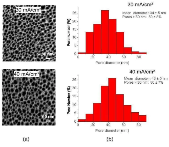
detection. Surface SEM observations and image analyses of PS samples after partial
oxidation have been used in order to estimate the mean pore diameter D which is about 34nm
and 43 nm respectively for the L and the H layer conditions (figure 4.a).
Figure 4: (a) Surface SEM images and (b) histograms of pore diameters for the studied anodization current densities of 30 mA/cm² and 40 mA/cm² after the partial oxidation step.
These pore sizes are large enough for APTES and GL molecule infiltration since the
molecule sizes are respectively 0.8 nm [23] and 0.7 nm [24]. As for the test molecule (BSA),
according to the pore size histograms (figure 4.b), very few pores have a dimension below
the largest size of the molecule which is 14 nm [25]. According to figure 4.b, the percentage
of pores with a size greater than 30 nm (which is twice the size of the molecule) is about 60%
and 80% respectively for L and H current densities conditions. So this protein molecule can
easily penetrate into the pores during the grafting process.
In order to determine the refractive index of PS single layers after each step of
functionalization, reflectance spectra have been measured and the volume fraction of each
constituent has been deduced by adjustment with the calculated spectra. For calculation
purposes, the thickness of each PS layer has been considered to be constant during the
process of functionalization according to cross sectional SEM observations.
In table 1, we report the different volume fractions and the refractive indexes deduced
from the adjustment of the experimental with theoretical reflectance spectra of PS single
layers after each step for the L and H current densities. As far as the initial porosity of the
sample is needed, we have performed gravimetric analyses and the results of these
measurements are in good agreement with the porosities deduced from optical method.
From the porosity value (CAir_2) and mean pore diameter (D) previously determined, we can
estimate the specific surface per volume unit by the following relation:
) ( . 4000 _2 nm D C Sp = Air m²/cm 3 [26] (7)
After the oxidation step, Sp= 81 m²/cm3 and 68 m²/cm3 respectively for L and H current
Steps 30 mA/cm² 40 mA/cm² (1) As prepared Cair_1 = 76 ± 1 %
n800 = 1.420 ± 0.025
Cair_1 = 83 ± 1%
n800 = 1.272 ± 0.021
(2) After oxidation CSi_2 = 17.8 ± 1.4%
CSiO2_2 = 13.02 ± 0.78% CAir_2 = 69.22 ± 0.58% n800 =1.364 ± 0.026 CSi_2 = 9.4 ± 1.8 % CSiO2_2 = 17.2 ± 1.7% CAir_2 = 73.28 ± 0.06% n800 = 1.220 ± 0.023
(3) After silanization CAPTES = 8.12 ± 0.13%
n800 = 1.408 ± 0.026 CAPTES = 7.75 ± 0.25 % n800 = 1.259 ± 0.025 (4) After coupling CGL = 8.50 ± 0.25% n800 = 1.456 ± 0.029 CGL = 7.25 ± 0.25 % n800 = 1.295 ± 0.025
(5) After grafting CBSA = 3.88 ± 0.38 %
CAir_5 = 48.72 ± 0.82 %
n800 = 1.478 ± 0.029
CBSA = 21.87 ± 0.34%
CAir_5 = 36.79 ± 0.82%
n800 = 1.407 ± 0.027
Table 1: Volume fraction of the different constituents in PS single layers after each step of elaboration, functionalization and grafting processes. The precision of the results has been deduced from the adjustment of experimental and theoretical spectra by considering the minimum and the maximum thickness for each PS layer.
Analyzing the silanization and coupling step results in table 1, we can notice that the volume
fractions of APTES and GL molecules are slightly lower for the H than for the L conditions.
This result can be explained by the specific surface which is also slightly lower in this
condition. On the contrary, for the protein grafting step, even though there is a higher internal
pore surface, the volume fraction of BSA is significantly lower for L than for H condition.
We attribute this result to the pore diameters which must be too small for infiltration of BSA
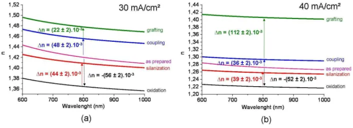
Figure 5 shows the evolution of the refractive index of the PS layers as a function of
wavelength at different biding steps which has been deduced from volume fractions obtained.
Figure 5 : Refractive index (n) evolution versus wavelength for each step of functionalization and refractive index variation (∆n) between two subsequent steps at λ = 800 nm for the two studied anodization current densities : 30 mA/cm² (a) et 40mA/cm² (b) . Values are deduced using the mean thickness of each PS layer.
The variation in the refractive index (1n) at λ = 800 nm is also indicated. After oxidation, 1n is negative because the silica index is lower than the silicon index. However, after
functionalization steps, 1n is positive due to the replacement of the air in the pores with added
molecules. The obtained values are correlated with the volume fraction of molecules
previously presented: 1n values are higher for the L current density condition except for the
protein grafting step because of a lower infiltration of BSA molecules.
4.2 Porous silicon microcavity
PS microcavity has been prepared by applying a periodic current density pulse train of 40
mA/cm² and 30 mA/cm² with an alternation of NA=NB=12 for the mirrors A and B defined in
precision for each layer of the microcavity have been deduced from the refractive index and
its variation previously calculated at this wavelength: eH = 162.8 ± 2.6 nm and
eL = 145.8 ± 2.0 nm respectively for 40 mA/cm² (H) and 30 (L) mA/cm². Then from the
anodization rates previously estimated we have deduced the anodization times for the H and L
current densities (figure 6.a).
Figure 6: (a) Schematic anodization current density variation used for microcavity elaboration (NA
= NB = 12); (b) Cross section SEM image of the as prepared microcavity.
Figure 6.b shows a cross sectional SEM micrograph of the as-prepared microcavity. The
estimated thickness is in the same order of magnitude as the aimed calculated thickness.
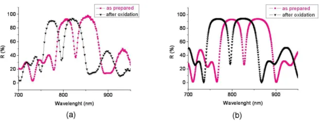
Reflectance spectrum of the as-prepared microcavity shows a resonant wavelength of 827.3
nm which is slightly different from the fixed one (800 nm). Cross sectional SEM observations
of the overall microcavity before and after different steps have not revealed any thickness
variation. So, for the reflectance calculations, we considered that the thickness of each layer
The as-prepared microcavity was functionalized in the same conditions as the single layer
ones. The reflectance measurements of the microcavity was obtained after each step, being
careful to take measurements in the same location (center part) (figures 7.a and 8.a).
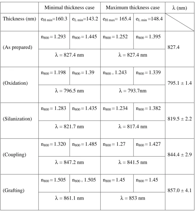
From the refractive index values previously determined for the studied PS single layers, we
calculated microcavity reflectance at each step of the process. In order to estimate the
precision of the resonant wavelength, we have simulated two microcavities using the minimal
or maximal refractive index previously estimated for the H and L layers. In every case, we
have considered that molecules were completely infiltrated into the overall thickness of the
microcavity.
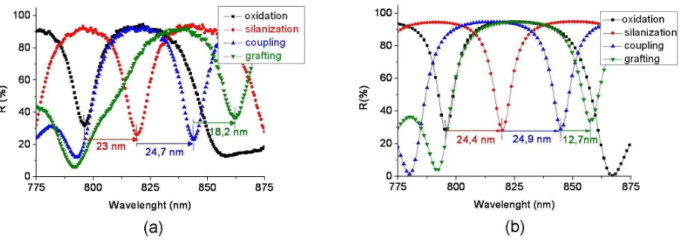
Figure 7: Reflectance spectra for as prepared and after partial oxidation of PS microcavity; a) experimental; b) theoretical with: eH = 165.4 nm eL=145.8 nm.
Figure 8: Reflectance spectra of POPS microcavity after oxidation, silanization, coupling and grafting steps: a) experimental; b) theoretical with eH = 165.4 nm eL=145.8 nm.
For the grafting step, the PS single layer study has revealed a low BSA infiltration for the
layer L which was attributed to small pore diameters. Constituting the limiting condition for
BSA infiltration in the microcavity, we used the values obtained in the L conditions for the
simulation of the microcavity after the grafting step. The different parameters for microcavity
simulations are indicated in table 2.
The spectra are presented in figure 7.b (before and after the oxidation step) and in figure 8.b
(from oxidation to grafting steps) considering the mean thickness of each PS layer. The shift
of the resonant wavelength of the microcavity, which is the consequence of the index
refraction variation of the layers between each step of the process, is noted after oxidation and
each functionalization step.
The comparison between the experimental and theoretical microcavity reflectances before
and after oxidation (figure 7) well shows very good agreement between calculated and
∆λexp = -31.3 nm. Therefore, the volume fraction of air, Si and Si02 determined by reflectance
spectra adjustment of the PS single layers can be used in the microcavity study.
Minimal thickness case Maximum thickness case λ (nm) Thickness (nm) eH min=160.3 eL min=143.2 eH max= 165.4 eL min =148.4
n800 =1.293 n800 =1.445 n800 =1.252 n800 =1.395 (As prepared) λ = 827.4 nm λ = 827.4 nm 827.4 n800 =1.198 n800 =1.39 n800 = 1.243 n800 =1.339 (Oxidation) λ = 796.5 nm λ = 793.7nm 795.1 ± 1.4 n800 = 1.283 n800 =1.435 n800 =1.234 n800 =1.382 (Silanization) λ = 821.7 nm λ = 817.4 nm 819.5 ± 2.2 n800 =1.320 n800 =1.485 n800 = 1.27 n800 =1.427 (Coupling) λ = 847.2 nm λ = 841.5 nm 844.4 ± 2.9 n800 =1.505 n800 = 1.505 n800 =1.45 n800 =1.45 (Grafting) λ = 861.1 nm λ = 853 nm 857.0 ± 4.1
Table 2: List of parameters used for microcavity simulation. The resonant wavelength value
and its precision are deduced for each step of the process.
Otherwise, the Q factors determined from experimental spectra (figures 7a and 8a) are quite
relatively low since the variation in the refractive index between the two alternating layers is
not very high (∆n # 0.15).
Comparing theoretical and experimental reflectance spectra in figure 8 for silanization and
coupling steps, we can see that wavelength shifts are also in the same order:
∆λth= 24.4 ± 3.6 nm and ∆λexp= 23 nm for silanization step; for coupling step,
∆λth = 24.9 ± 5.1 nm and ∆λexp = 24.7 nm. For these steps, the volume fraction of air, APTES
and GL determined by reflectance spectra adjustment of the PS single layers are in the same
order in the microcavity. Moreover such experimental shift values (∆λ = 19 nm) have been obtained by Palestina and al. [9] after the silanization step for almost identical pore size.
For the grafting step (figure 8), the theoretical wavelength shift value is lower than the
experimental one: ∆λth = 12.7 ± 7.0 nm and ∆λexp = 18.2 nm. For the simulation, we have
considered that there is a total and homogeneous infiltration throughout all the layers of the
microcavity. For the small molecule sizes such as APTES and GL, we can consider that this is
probably the case, but for the BSA molecules, whose size is larger, it is less likely and we
could consider a gradient of BSA infiltration in the simulation microcavity spectra. However,
if we take into account the precision, the experimental and theoretical results also correlate.
Then, the theoretical and experimental values obtained from the single layer study are quite
similar throughout the process of functionalization, meaning that the single layer results can
5 Conclusion
In this paper a study of refractive index variation after each step of functionalization of POPS
layers for two porosity values (L and H) is presented. BSA protein has been used as test
molecule. Then, theoretical reflectance spectra of the layers have been calculated using the
Bruggemann model. Volume fraction of the different constituents and refractive index of
layers were determined after each step by adjustment of theoretical reflectance spectra with
experimental ones. The specific surface of each PS layer has been deduced from the porosity
and the mean pore diameter estimated by surface SEM observations. The comparison of
biomolecule volume fractions calculated for L and H single layers was well correlated to the
difference of their specific surface except for BSA molecules. In the L single layer, the
infiltration of BSA was found to be significantly less efficient than in the H single layer
because of small pore size.
A functionalized microcavity was prepared using the two different porosities of PS previously
studied. In addition, from refractive index determined from PS layers study, a theoretical
microcavity has been simulated using the matrix transfer model at each step of
functionalization. The volume fractions values obtained in H and L single layer studies have
been used except for the grafting step for which we took into consideration the limiting BSA
infiltration condition in the overall depth of the microcavity. The comparison of theoretical
and experimental microcavity reflectance spectra has revealed a good concordance of the
different resonant wavelength shifts.
These results show that the method we applied in order to determine the volume fraction of
different constituents is well adapted and efficient to control the functionalization process of
POPS. Such a study on PS single layers will enable us to predict the functionalization of
other PS optical structures such as waveguides for the development of a label-free optical
6 References
[1] I. Rendina, I. Rea, L. Rotiroti, L. De Stefano, Physica E 38 (2007) 188–192.
[2] S. Ozdemir, J. and L. Gole, Current Opinion in Solid State and Materials Science 11 (2007) 92–100
[3] A. Jane, R. Drovnov, A. Hodges and N. H. Voelcker, Trends in Biotechnology vol.27, 4 (2009) 230-239.
[4] P. Rivolo, P. Pirasteh, A. Chaillou, P. Joubert, M. Kloul, J.-F. Bardeau and F. Geobaldo,
Sensors and Actuators B 100 (2004) 99–102.
[5] M. Thust, M.J. Scho
ë
ning, P. Schroth, Ü . Malkoc, C.I. Dicker, A. Steffen, P. Kordos and H. Lüth, Journal of Molecular Catalysis B: Enzymatic 7_1999.77–83.[6] H. Föll, M. Christophersen, J. Carstensen and G. Hasse, Materials Science and Engineering R 39 (2002) 93–141.
[7] G. Rong, A. Najmaie, J. E. Sipe, S. M. Weiss, Biosensors and Bioelectronics 23 (2008) 1572–1576.
[8] S. Setzu , P. Ferrand, R. Romestain, Materials Science and Engineering B69–70 (2000) 34–42.
[9] G. Palestino, R. Legros, V. Agarwal, E. Pérez, C. Gergely, Sensors and Actuators B 135 (2008) 27–34.
[10] H. Ouyang, C. C. Striemer, and P. M. Fauchet, Applied Physics Letters 88, (2006) 163108 1-3.
[11] V. Torres-Costa, F. Agullo-Rueda, R.J. Martin-Palma and J.M. Martinez-Duart, Optical Materials 27 (2005) 1084–1087.
[12] F. Geobaldo, P. Rivoloa, P. Ugliengo, E. Garrone, Sensors and Actuators B 100 (2004) 29–32.
[13] E. J. Anglin, L. Cheng, W. R. Freeman, M. J. Sailor, Advanced Drug Delivery Reviews 60 (2008) 1266–1277.
[14] H. Ouyang,_C. C. Striemer, and P. M. Fauchet, Applied Physics Letters 88, (2006)
163108 1-3.
[15] F. Cui, Y. Cui, H. Luo, X. Yao, J. Fan and Y. Lu, Chinese Science Bulletin, vol.511, n°18 (2006) 2201-2207.
[16] S.B. Adeloju and A.T. Lawal, Analytica Chimica Acta, 691 (2011) 89-94.
[17] D. S. Bethune, J. Opt. Soc. Am. B, Vol. 6, 5 (1989) 910-916.
[18] Handbook of chemistry and physics, 78th ed.. ; Lide, D.R., Ed.; CRC Press : Boca Raton, FL, 1997.
[19] http://www.sigmaaldrich.com.
[20] D.E. Aspnes, Thin Solid Films, 89 (1982) 249.
[21] K. Baral, R. Herino, G. Bomchil, J. Appl. Phys., 59 (2) (1986) 439.
[22] E. V. Astrova, V. B. Voronkov, A. D. Remenyuk, and V. B. Shuman, Semiconductors,
33, (1999) 1149-1155.
[23] H. Ouyang and P. M. Fauchet, SPIE Optics East 2005.
[24] M. Lee and P. M. Fauchet, 15, No. 8, Optics express (2007) 4530.
[25] K. Nakamura, K. Matsumoto, Journal of Membrane Science 145 (1998) 119-128.
