HAL Id: tel-01276404
https://tel.archives-ouvertes.fr/tel-01276404
Submitted on 19 Feb 2016HAL is a multi-disciplinary open access archive for the deposit and dissemination of sci-entific research documents, whether they are pub-lished or not. The documents may come from teaching and research institutions in France or abroad, or from public or private research centers.
L’archive ouverte pluridisciplinaire HAL, est destinée au dépôt et à la diffusion de documents scientifiques de niveau recherche, publiés ou non, émanant des établissements d’enseignement et de recherche français ou étrangers, des laboratoires publics ou privés.
Contribution to the study of the use of brain-computer
interfaces in virtual and augmented reality
Jonathan Mercier
To cite this version:
Jonathan Mercier. Contribution to the study of the use of brain-computer interfaces in virtual and augmented reality. Graphics [cs.GR]. INSA de Rennes, 2015. English. �NNT : 2015ISAR0018�. �tel-01276404�
THESE INSA Rennes
sous le sceau de l’Université européenne de Bretagne pour obtenir le titre de DOCTEUR DE L’INSA DE RENNES Spécialité : Informatique
présentée par
Jonathan Mercier-Ganady
ECOLE DOCTORALE : MATISSE LABORATOIRE : IRISA
Contribution to the Study of
the Use of Brain-Computer
Interfaces in Virtual and
Augmented Reality
Thèse soutenue le 12.10.2015
devant le jury composé de : Bruno Arnaldi
Professeur, INSA de Rennes / Président
Indira Thouvenin
Professeur, Université de Technologie de Compiègne / Rapporteuse
Martin Hachet
Chargé de Recherche HDR, Inria Bordeaux / Rapporteur
Guillaume Moreau
Professeur, École Centrale de Nantes / Examinateur
Anatole Lécuyer
Directeur de Recherche, Inria Rennes / Directeur de thèse
Maud Marchal
Contribution to the Study of the Use of
Brain-Computer Interfaces in
Virtual and Augmented Reality
Jonathan Mercier-Ganady
Reality didn’t have to be real. Maybe if conditions were right, it just had to be what people believed... Terry Pratchett, Moving Pictures
Thanks
First, I would like to thank the members of my jury for agreeing to evaluate my work and my manuscript: Pr. Bruno Arnaldi for agreeing to preside my thesis defense committee, Pr. Indira Thouvenin and Dr. Martin Hachet for being rapporteurs on my manuscript, and finally Pr. Guil-laume Moreau for his examination of my work. Thank you very much for your comments and your useful remarks.
I would also like to express my gratitude to Dr. Anatole Lécuyer and Dr. Maud Marchal for their role as doctoral supervisor and supervisor, respectively. Thank you very much for your good mood, your continued support, your valuable advice and your constant influx of great ideas. Working with you has been amazing.
Further acknowledgement and thanks are due to my co-authors: Dr. Émilie Loup-Escande, Dr. Fa-bien Lotte, Dr. Laurent George, and Colomban Busson.
Through these three years I have had the chance to work at the IRISA/Inria with brilliant peo-ple from the Hybrid team, and its predecessor, the VR4i team. First I would like to mention Dr. Jussi Tapio Lindgren, who has been a great colleague during all this time, sharing his knowledge and answering numerous questions. Many thanks also to Andéol Évain for being always ready to help, and Jozef Legény for his skills as an engineer, photograph, and graphic designer. I would also like to acknowledge the members of the “haptics office”: Dr. Merwan Achibet for his good mood and his good advice, Dr. Anthony Talvas, Dr. Adrien Girard, Dr. Fabien Danieau, and Benoît Le Gouis. Many thanks to all the members of the Hybrid/VR4i teams, you were always ready to exchange ideas about anything and it was a real pleasure to discuss with all of you. Additional gratitude is offered to all my test subjects that have had EEG gel in their hair, it has not been sticky in vain. Finally, many thanks to my parents, my family and my friends for their support. A special thanks is due to my parents and Pierre Mercier for the excellent proofreading of my manuscript.
Contents
Thanks i Contents iii Acronyms 1 Introduction 3 1 Related work 91.1 Brain-computer interfaces: short overview and basic principles. . . 9
1.1.1 Brain structure and brain data acquisition . . . 10
1.1.2 Common electroencephalography markers used in brain-computer inter-face setups . . . 11
1.1.2.1 Electroencephalography rhythms . . . 11
1.1.2.2 Event-related potentials . . . 12
1.1.2.3 SSVEP . . . 13
1.1.3 Concentration and relaxation mental states . . . 14
1.2 Combining brain-computer interfaces and other user inputs . . . 14
1.2.1 Main concepts behind hybrid brain-computer interfaces . . . 15
1.2.1.1 Mixed or pure hybrid brain-computer interfaces . . . 15
1.2.1.2 Sequential or simultaneous processing . . . 16
1.2.2 Most commonly used input devices in hybrid brain-computer interfaces . . 16
1.2.3 Representative examples of hybrid brain-computer interfaces . . . 17
1.2.3.1 Pure hybrid brain-computer interfaces . . . 17
1.2.3.2 Mixed hybrid brain-computer interfaces . . . 18
1.2.4 Conclusion . . . 21
1.3 Combining brain-computer interfaces and virtual/augmented reality . . . 21
1.3.1 Brain-computer interfaces and virtual reality . . . 21
1.3.1.1 Representative examples of virtual reality applications using a brain-computer interface . . . 21
1.3.1.2 Passive brain-computer interfaces and virtual reality . . . 25
1.3.1.3 Hybrid brain-computer interface and virtual reality . . . 25
1.3.1.4 Motor activity, brain-computer interfaces, and virtual reality. . . 26
1.3.2 Neurofeedback and virtual reality. . . 28
1.3.3 Brain-computer interfaces and augmented reality. . . 28
1.3.3.1 Manipulation of real objects . . . 28
1.3.3.2 Manipulation of virtual objects . . . 31
1.3.3.3 Brain activity visualization and analysis . . . 33
1.3.3.4 Discussion . . . 34
2 Can we use a brain-computer interface and manipulate another input
de-vice at the same time? 37
2.1 Experimental method . . . 38 2.1.1 Population . . . 38 2.1.2 Experimental apparatus . . . 38 2.1.3 Experimental plan . . . 39 2.1.4 Procedure . . . 40 2.1.5 Collected data. . . 40 2.2 Results . . . 40 2.2.1 Classifier results . . . 40 2.2.2 Questionnaire results . . . 41 2.3 Discussion . . . 42 2.4 Conclusion . . . 42
3 Real-time brain activity visualization using augmented reality 43 3.1 Mind-Mirror: view your brain in activity as in a mirror . . . 43
3.1.1 Related work on mirror-based augmented reality . . . 44
3.1.2 The Mind-Mirror system . . . 45
3.1.2.1 Concept . . . 45 3.1.2.2 System description . . . 45 3.1.2.3 Visualization tools . . . 46 3.1.3 Pilot study . . . 48 3.1.3.1 Experimental apparatus. . . 49 3.1.3.2 Population . . . 49 3.1.3.3 Experimental plan . . . 49 3.1.3.4 Collected data . . . 50 3.1.4 Results . . . 50
3.1.4.1 Classification performance results . . . 50
3.1.4.2 Questionnaire results . . . 51
3.1.5 Discussion . . . 51
3.2 Mind-Window: multi-user visualization of brain activity . . . 52
3.2.1 Concept . . . 52
3.2.2 System description . . . 53
3.2.3 Visualization techniques . . . 54
3.2.4 Implementation . . . 56
3.2.5 Use cases and applications. . . 56
3.3 Mind-Inside: telepresence inside one’s brain . . . 57
3.3.1 Introduction . . . 57
3.3.2 System . . . 57
Contents
4 Towards smart clothes based on brain-computer interfaces and augmented
reality 61
4.1 The virtual dressing room. . . 62
4.1.1 Previous work related to mirror-based virtual dressing rooms . . . 62
4.1.2 System description . . . 63
4.2 The Invisibility Cloak and the B-C-Invisibility Power . . . 66
4.2.1 The Invisibility Cloak . . . 66
4.2.1.1 Concept . . . 66
4.2.1.2 Related work and positioning . . . 67
4.2.2 The B-C-Invisibility Power . . . 67
4.2.2.1 Concept . . . 67 4.2.2.2 System description . . . 67 4.2.3 Pilot study . . . 68 4.2.3.1 Experiment description . . . 69 4.2.3.2 Results . . . 69 4.2.4 Discussion . . . 70 4.3 Conclusion . . . 71 5 Conclusion 73 5.1 Contributions . . . 73 5.2 Future work . . . 74 A French abstract 75 Author’s references 91 References 93
Acronyms
AR Augmented Reality
BCI Brain-Computer Interface
CAVE Cave Automatic Virtual Environment EEG ElectroEncephaloGraphy
HMD Head-Mounted Display
SSVEP Steady State Visually Evoked Potential VR Virtual Reality
Introduction
C
ontrollinga virtual world using one’s brain activity has been already and early considered by both researchers and artists. Science-fiction has provided examples of such interfaces. For instance, in the movie “The Matrix”, humans have a connection port in the back of the head that allows them to connect to and interact with a virtual world called the Matrix (see Figure 1). In “Source Code”, another movie released in 2011, a soldier is embodied into a deceased person during her last 8 minutes in order to identify a bomber. This soldier is connected to a Brain-Computer Interface (BCI) that allows him to observe and interact with an alternate reality. These fictional examples pave the way for new uses of BCIs, especially to control virtual or real worlds.(a) (b)
Figure 1 – Science-fiction illustrations of a brain-computer interface used to interact with a virtual world. (a) Picture from the movie “The Matrix”. Warner Bros, 1999. (b) Picture from the movie “Source Code”. Summit Entertainment, 2011.
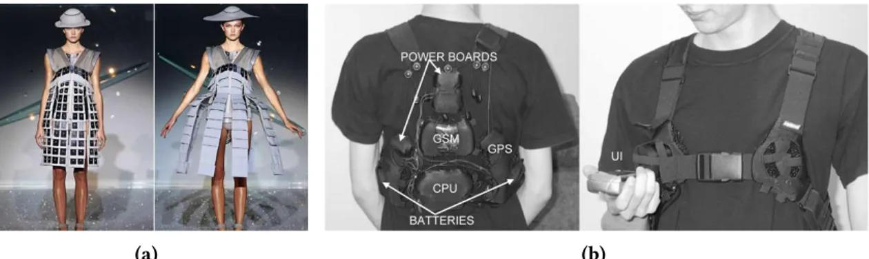
The work presented in this manuscript concerns the use of BCIs in both Virtual Reality (VR) and Augmented Reality (AR). This work was part of a collaborative research project called Homo Tex-tilus. It aimed at studying the future of smart clothes which are made up with smart textiles, “able to sense stimuli from the environment, to react to them and adapt to them by integration of function-alities in the textile structure” [Van Langenhove and Hertleer,2004]. Smart clothes are “ordinary clothing, augmented with electrical or non-electrical components and intelligent fabrics” [Rantanen et al.,2000]. They can integrate electronic components, mechanical actuators, but also sensors to measure heartbeat, temperature, etc. Smart clothes prototypes have already been produced. Some of them have been displayed on fashion shows (seeFigure 2, (a)). A “survival smart clothing pro-totype” has been designed by Rantanen et al., which illustrates another use-case for smart clothes (seeFigure 2, (b)) [Rantanen et al.,2002].
In the context of the Homo Textilus project, the objective of this thesis was to integrate a brain-computer interface to real or virtual smart clothes. Thus the final objective of this PhD was to study the combination of BCI, VR and AR systems for the design of novel generations of smart clothes.
(a) (b)
Figure 2 – Two examples of smart clothes. (a) Smart clothes using actuators to change their shape. Design by Hussein Chalayan. Photo: Agence France Presse. (b) The supporting structure of smart clothing for the arctic environment [Rantanen et al.,2002].
Definitions:
Brain-computer interface: A brain-computer interface is defined by Wolpaw et al. as a “com-munication system that does not depend on the brain’s normal output pathways of peripheral nerves and muscles” [Wolpaw et al.,2000]. A BCI provides an alternate route for sending commands to com-puters or other devices. ElectroEncephaloGraphy (EEG), one of the most frequently used techniques within the BCI community to access to brain activity, is the “recording of electrical activity along the scalp produced by the firing of neurons within the brain” [Niedermeyer and da Silva,2005]. Since BCIs can be used to send commands, they can be associated with VR as a novel input device [Edlinger et al.,2011].
Virtual reality: Earlier definitions of virtual reality were purely “technologically-based”. For instance, Greenbaum described VR as “an alternate world filled with computer-generated images that respond to human movement” [Greenbaum,1992]. Later definitions, such as the one proposed by Steuer, define VR using either this “technological-based approach” or in terms of “presence”. Steuer defines presence as “the sense of being in an environment”, telepresence as “the experience of presence in an environment by means of a communication medium” and, finally, VR as “a real or simulated environment in which a perceiver experiences telepresence” [Steuer,1992].
Augmented reality: Milgram et al. proposed the concept of “reality-virtuality continuum” (seeFigure 3), and “mixed reality” [Milgram et al.,1995]. Mixed reality is defined as an environment “in which real world and virtual world objects are presented together within a single display”. Real environments and virtual environment are located on each side of this continuum. According to Milgram et al., AR is a subset of mixed reality, close to the real environment. AR can be defined as being a reality “in which 3D virtual objects are integrated into a 3D real environment in real time” [Azuma et al.,1997]. AR and VR share the presence of virtual objects with which users can interact.
Real Environment Augmented Reality Augmented Virtuality Virtual Environment Mixed Reality
Introduction
Combining brain-computer interfaces with virtual reality and augmented reality
The last decade has seen an increase of interest in using brain-computer interfaces within virtual environments [Lotte et al.,2013a], and more specifically, within video-games [Lécuyer et al.,2008;
Nijholt et al.,2009]. Indeed, BCIs were essentially used for medical purposes, i.e. as a communication pathway for paralyzed persons [McFarland and Wolpaw,2011], but new use-cases for healthy users are appearing [Allison et al.,2007a].
Lotte proposed an overview of the limitations and perspectives of the use of BCIs for video-games [Lotte,2011]. He listed a number of possible limitations when using an EEG-based BCI: notably the requirement for the user to remain static to prevent EEG noise, the low amount of commands that can be distinguished using only the BCI, and the low performance in terms of latency compared to classical input devices. Overcoming these limitations could be achieved by improving the BCI technologically, but also by adapting the interaction techniques. An interaction technique is “the fusion of input and output, consisting of all software and hardware elements, that provides a way for the user to accomplish a task” [Tucker,2004]. One of these adaptations could be the use of a hybrid BCI.
A hybrid BCI is defined by Pfurtscheller as being “composed of two BCIs, or at least one BCI and another system” [Pfurtscheller,2010]. One possible use of hybrid BCIs is to enhance the performance of a system by supplementing one component with another. A classical example of a sequential hybrid BCI is the “brain switch” [Pfurtscheller,2010], where one BCI is used as a trigger for the activation (or deactivation) of another BCI.
More and more, instead of being considered as a replacement, BCIs could therefore be seen as a complement to classical interfaces [Lécuyer et al.,2008].
Challenges
Figure 4 displays the architecture and the components of a VR/AR system using a BCI as a complement to another input device manipulated with motor activity and represented by a hand. An interaction technique receives user motor/cognitive activity data and sends commands to the virtual environment. The result can be either augmented or virtual reality, depending on whether the virtual environment is associated with the real environment or not. A visual display sends images that can be perceived by the eyes and interpreted by the brain. This figure illustrates the various combinations that can be achieved between multiple inputs (BCI or not) and VR/AR displays.
Motor activity data Input Device Brain-Computer Interface Neural activity data Motor activity data Brain activity data Virtual Environment Commands Virtual Reality Augmented Reality Visual Display Association Real Environment Virtual data
Real and virtual data Images Motor Input Cognitive Input Interaction Technique Virtual objects Real images Images Images
In this PhD we focus on several challenges concerning the combination of bracomputer in-terface and virtual/augmented reality systems:
• Compatibility of brain-computer interfaces and virtual/augmented reality systems: testing the compatibility between BCIs and VR/AR can be divided into three levels: hardware, software, and usage. On the hardware level, are the system components compatible with each other? What impairs the combination of two hardware components? At the software level, what software components could be developed to enable and facilitate the simultaneous use of a BCI and VR/AR? Finally, at the usage level, is it possible for people to use both a BCI and a VR/AR system at the same time?
• Learning of BCI-based interaction in virtual environments: can users be trained to con-trol their brain activity while being immersed in a virtual environment? How can their brain activity be exploited to better interact in VR/AR systems? What type of novel visualization tools exploiting VR/AR technologies could be developed to achieve these goals?
• Novel usages of brain-computer interfaces combined with virtual/augmented reality: what novel uses can be found for systems combining BCIs and VR/AR? How can these uses be evaluated in terms of performance and usability? Could smart clothes benefit from BCI technology, possibly in combination with VR/AR systems?
The Homo Textilus project
This PhD was funded by the administrative region of Brittany and the French National Research Agency within the Homo Textilus project (February 2012 – September 2015). The Homo Textilus project aimed at studying the sociological impact of the next generation of smart clothes. More specifically, studying how smart clothes could be accepted by users, listing the technological limi-tations and challenges, producing a state of the art on these clothes and, finally, designing and de-veloping prototypes. The project involved six partners: Tomorrowland, Lutin, Lip6, Inria, GEMTEX, and RCP Design Global. The role of our laboratory (Inria) in this project was to study potential and technological challenges of the integration of BCIs with smart clothes and to design and conceive prototypes and proofs of concept.
Within this project, BCIs were seen as a novel input/sensors and were studied to provide a way to measure various cognitive attributes of the wearer, and modify the virtual environments and/or clothes attributes/actuators accordingly. VR/AR could also provide a testbed for such novel smart clothes whose production is often complicated and expensive.
Thesis methodology
The methodology adopted in this thesis follows the 4 stages described thereafter:
1. Feasibility study on compatibility of virtual reality and brain-computer interface systems: we conducted an evaluation of the BCI performance when simultaneously using a BCI and another input device. A muscular task requiring a progressive amount of engage-ment was used. In addition, a cognitive task was also performed to control the BCI. The success rate of both tasks was measured.
2. Learning and visualization tools for brain activity based on VR/AR: we have proposed new tools allowing users to visualize their brain activity in real-time. These tools could make learning how to control brain activity easier. Various prototypes for real-time 3D visualization of brain activity in VR/AR have been designed and evaluated.
Introduction
3. Virtual reality testbed for smart clothes: we have designed a VR/AR testbed to test and evaluate smart clothes applications with a minimal investment of time and resources. This system allowed users to test the wearing of smart clothes and interact with various kinds of inputs.
4. Design of novel concepts of smart clothes based on BCIs: we have studied the design of new concepts of smart clothes based on BCIs. We have extended our VR/AR testbed to inte-grate a BCI, allowing to adapt various properties of the virtual clothes. We have designed and evaluated a prototype called the “Invisibility Cloak”, allowing users to camouflage themselves in AR using a BCI.
Contributions
Chapter 1 is an overview of related work about brain-computer interfaces and virtual/augmented reality. The main characteristics of BCIs are first provided, followed by a description of the different types of BCIs and some examples. The chapter also provides an overview of the previous uses of BCIs in VR and AR.
Chapter 2 proposes to study whether a brain-computer interface can be used simultaneously with another input device. To this end, a game-like prototype serves as a support for a study on the effects of muscular activity on the BCI performance. A concentration or relaxation mental task is performed in combination with a muscular task of varying intensity. Three levels of muscular activity are tested: from no motion at all to a highly demanding muscular activity. The performance of the BCI is measured in all combinations.
Chapter 3 introduces novel tools for the visualization of brain activity in real-time based on virtual/augmented reality. A first prototype called the “Mind-Mirror” provides a way for users to visualize their own brain activity in real-time in their head as if they were looking into a mirror. A second prototype called the “Mind-Window” is a mobile and multi-user setup where tablet com-puters can be used to visualize the brain activity of another person in real-time. Finally, a third prototype called “Mind-Inside” is a highly immersive VR system based on a Head-Mounted Display (HMD) and enabling telepresence and immersion inside one’s brain. A user study evaluates both the objective and subjective performance of the Mind-Mirror prototype, compared to a more classical visualization. One of the most promising applications for these prototypes is neurofeedback, which is “a form of behavioural training aimed at developing skills for self-regulation of brain activity” [Heinrich et al.,2007].
Chapter 4 targets the use of brain-computer interfaces for controlling smart clothes. Several prototypes and a user study concern this direction. A first prototype shows how users can wear and test virtual clothes and other garments thanks to AR. A second prototype enables the control and the change of appearance of these virtual clothes depending on the mental state of the BCI user. Finally, an experimental study evaluates how well participants can control an invisibility power within a virtual environment with the help of a BCI. This leads to the concept of an “Invisibility Cloak” with which participants can camouflage themselves in AR using a BCI.
Chapter 1
Related work
Contents
1.1 Brain-computer interfaces: short overview and basic principles . . . 9
1.1.1 Brain structure and brain data acquisition. . . 10
1.1.2 Common electroencephalography markers used in brain-computer interface setups . . . 11
1.1.3 Concentration and relaxation mental states . . . 14
1.2 Combining brain-computer interfaces and other user inputs . . . 14
1.2.1 Main concepts behind hybrid brain-computer interfaces . . . 15
1.2.2 Most commonly used input devices in hybrid brain-computer interfaces . . . 16
1.2.3 Representative examples of hybrid brain-computer interfaces . . . 17
1.2.4 Conclusion . . . 21
1.3 Combining brain-computer interfaces and virtual/augmented reality . . . 21
1.3.1 Brain-computer interfaces and virtual reality . . . 21
1.3.2 Neurofeedback and virtual reality . . . 28
1.3.3 Brain-computer interfaces and augmented reality . . . 28
1.4 Conclusion . . . 36
This chapter provides an overview of related work in the field of Brain-Computer Interfaces (BCIs) and their combination with other user inputs notably when related to Virtual Reality (VR) and/or Augmented Reality (AR). The first section of this chapter describes how BCIs operate: what are the main brain structures and how is the brain data acquired. The most common ElectroEn-cephaloGraphy (EEG) markers are then described. The second section of this chapter deals with the concept of hybrid BCIs, which represents a combination of a BCI with another input device. This section notably describes some representative examples of systems based on hybrid BCIs. The final section of this chapter surveys the combination of a BCI with VR and AR systems.
1.1 Brain-computer interfaces: short overview and basic principles
A brain-computer interface is a communication and control channel that “acquires brain signals, analyses them, and translates them into commands that are relayed to an output device to carry out a desired action” [Shih et al.,2012] and “does not depend in any way on the brain’s normal output pathways” [McFarland and Wolpaw,2011]. Analysis of brain signals requires some knowledge of the inner workings of the human brain. This section provides an overview of the brain structure principles and how brain data acquisition can be performed, as well as how this data can be inter-preted. This section refers to the following articles: [McFarland and Wolpaw,2011;Shih et al.,2012] or surveys: [Allison et al.,2007b;Mason et al.,2007], and to the following book: [Niedermeyer and da Silva,2005].1.1.1 Brain structure and brain data acquisition
A human brain is divided into three parts: the brain stem, the cerebellum and the cerebrum. The cerebrum is itself divided into two hemispheres: left and right. The surface of the cerebrum is called the cortex and is divided into four zones called “lobes” (seeFigure 1.1). The frontal lobe is used for cognitive functions such as speech, movements and other executive functions. The temporal lobe deals with auditory, visual and language functions. It is also used for emotional processing. The parietal lobe is used for reading/writing, language comprehension, attention and spatial awareness. Lastly, the occipital lobe is involved in visual processing [Gray,1918].
Figure 1.1 – Lateral view of the brain lobes. Derived from [Gray,1918].
Recording brain activity can be achieved by using electrical fields, blood pressure, or magnetic fields. Gathering this information is called “acquisition”. Retrieval of brain data can be achieved with the help of invasive or non-invasive methods, depending on whether the measurement device is placed on the brain tissues themselves or on the scalp. A BCI is then called “invasive” or “non-invasive” [McFarland and Wolpaw,2011]. Invasive systems are less prone to noise than non-invasive interfaces, but need a surgical operation to be placed on the user and have to be removed or replaced after some time due to the rejection phenomenon. While invasive BCIs mainly use electrocorticog-raphy [Leuthardt et al.,2006], non-invasive BCIs can use various methods: EEG [Niedermeyer and da Silva,2005], near-infrared spectroscopy [Bunce et al.,2006], magnetoencephalography [ Hämäläi-nen et al.,1993], and functional magnetic resonance imaging [Ogawa et al.,1992]. Each approach differs in cost, efficiency and mobility. Many BCI systems use EEG because of its ease of use and low cost compared to magnetoencephalography or functional magnetic resonance imaging devices. EEG uses active or passive electrodes placed on the scalp to gather data from the brain thanks to the electric potentials it emits [Niedermeyer and da Silva,2005].
Non-invasive medical applications of BCIs most often use EEG. The BrainAmp1and the g.USBamp2 are two examples of medical EEG amplifiers, that are used with proprietary EEG electrodes. In re-cent years, new non-medical uses of EEG-based BCIs have appeared in fields like entertainment and video-games. Novel EEG hardwares were produced, with a lower cost, such as the Emotiv EPOC3. Duvinage et al. compared a medical and a non-medical EEG device in a specific
applica-tion [Duvinage et al.,2012]. Comparing classification results of a medical system called “ANT” and the EPOC, they logically found out that the medical system had better results. However the EPOC
1http://www.brainproducts.com/productdetails.php?id=7
2http://www.gtec.at/Products/Hardware-and-Accessories/g.USBamp-Specs-Features 3http://www.emotiv.com/epoc/
Brain-computer interfaces: short overview and basic principles
allowed for above chance classification results, which suggested its usability in this particular sce-nario. According to the authors, this device is suitable for non-critical applications like video-games, but not for medical applications.
Electrical fields emitted by the neurons are thus measured with the help of EEG [Niedermeyer and da Silva,2005]. These fields are received by electrodes that produce a signal of a weak amplitude. The EEG electrodes are placed on the surface of the head, often attached to a cap. Gel or salted water are used to enhance the conductivity between the head and the electrodes. This implies that a certain amount of time (usually 20 minutes) is needed to setup any system that uses EEG. Electrodes are commonly placed using the 10-20 system (seeFigure 1.2).
(a) (b)
Figure 1.2 – The 10-20 international electrodes placement system [Tanner et al.,2011]. (a) Axial view. (b) Sagittal view.
Electroencephalography has also a very good temporal resolution (milliseconds) compared to other methods such as functional magnetic resonance imaging or positron emission tomography (seconds). Unlike functional magnetic resonance imaging, EEG has a bad spatial resolution because of the nature of electric waves and their diffusion. Surface brain activity is easier to detect than internal activity. EEG requires a non-trivial data analysis because of the low signal-to-noise ratio induced by muscular activity. However, some studies have shown that some motion can still be performed while using an EEG-based BCI [Lotte et al.,2009].
1.1.2 Common electroencephalography markers used in brain-computer inter-face setups
Electroencephalography markers are variations of the signal retrieved from the brain data and ex-ploitable in applications using a brain-computer interface. Commonly used markers in BCIs are: EEG rhythms, event related paradigms, evoked potentials, and concentration/relaxation mental states. These markers will be described thereafter.
1.1.2.1 Electroencephalography rhythms
Rhythms are oscillations that can be observed in specific locations of the brain and at specific fre-quency bands. They can provide some information about a mental state and can be voluntarily controlled [Niedermeyer,2004]. These rhythms are called alpha, beta, gamma, delta, theta, and mu. • Alpha: the alpha rhythm (8-13Hz) is present in the posterior (occipital) part of the brain and is higher on the non-dominant side (seeFigure 1.3, (a)). It is mostly observed when closing the eyes or being in a relaxed state: higher alertness reduces its amplitude;
• Beta: the beta rhythm (13-30Hz) can be detected when the user is awake and conscious and is affected by movements of the user (seeFigure 1.3, (b));
• Gamma: the gamma rhythm (greater than 30Hz) is linked to cognitive and motor activity and is difficult to measure using scalp-based EEG (seeFigure 1.3, (c));
• Delta: the delta rhythm (1-4Hz) is mostly observed in adults during deep sleep (seeFigure 1.3, (d));
• Theta: the theta rhythm (4-8Hz) can be seen in young children during drowsiness and is known to form a spike when the user is trying to repress a response or an action [Futagi et al.,
1998] (seeFigure 1.3, (e));
• Mu: the mu rhythm (8-13Hz) is motor-based and varies when the user is moving [Wolpaw and McFarland,2004] (seeFigure 1.3, (f)).
(a) (b)
(c) (d)
(e) (f)
Figure 1.3 – EEG recordings performed on the Oz position and filtered to show each rhythm. Record-ing and figures by Hugo Gamboa.
1.1.2.2 Event-related potentials
It has been observed that some events such as sensory stimuli, motor activity, and memory tasks have a direct impact on the rhythms described in the previous section [Pfurtscheller and Lopes da Silva,1999]. An increase in rhythmic activity is called an “event related synchronization” while a decrease is called an “event related desynchronization”. Event related desynchronizations can be encountered a few milliseconds before a movement is performed, or even imagined (seeFigure 1.4, (a)). For example, imagining a right hand movement will trigger an event related desynchronization in the mu and beta rhythms on the left motor cortex.
Event related desynchronization is used in a paradigm called “motor imagery”, which mostly relies on the alpha and beta rhythms. While motor imagery represents imagined motor activity, motor execution represents the executed motor activity. After the execution or imagination of a motor action, a so-called alpha- or beta-rebound can be detected (seeFigure 1.4, (b)). Motor imagery allows users to send commands to a BCI by imagining performing a movement [Pfurtscheller and Neuper,2001].
The P300 is a positive waveform appearing 300 ms after the occurrence of a rare and relevant stimulus [Donchin et al.,2000]. The P300 paradigm is commonly used with a grid of letters called a “P300 speller” (seeFigure 1.5) [Krusienski et al.,2008]. This grid is composed of letters that can be either dark or bright (flashing). The user has to focus at one of the letters and mentally counts how
Brain-computer interfaces: short overview and basic principles
(a) (b)
Figure 1.4 – Two brain activity recordings. (a) Raw EEG data recorded during right finger movement showing event related desynchronization and event related synchronization. A cue stimulus (CS) followed a warning signal (WS) indicating the side of movement (right/left) to be performed (image and caption taken from Pfurtscheller et al. [Pfurtscheller,1992]). (b) Alpha and beta band (rhythms) variations when using motor imagery [Pfurtscheller and Neuper,2001].
many times the letter has flashed. This allows the system to detect what the focused letter is. This paradigm has been successfully used on paraplegic patients in a medical context, allowing them to communicate “using thoughts” [Hoffmann et al.,2008].
Figure 1.5 – A P300 speller grid [Krusienski et al.,2008].
1.1.2.3 SSVEP
Steady State Visually Evoked Potential (SSVEP) is a type of evoked potentials that use flickering visual elements whose frequency can be retrieved from the brain electrical signals when the user is looking at them [Müller-Putz et al.,2005]. These elements can be displayed on a computer screen or with light-emitting devices like LEDs. This allows to recognize which element is being looked at, and enables the user to send one command per frequency. A review proposed by Zhu et al. shows that there is no definitive limit on the amount of frequencies that can be used [Zhu et al.,2010]. SSVEP has been employed for navigation control such as in [Lee et al.,2010] or in video-games like in [Lalor et al.,2005] with great efficiency [Beverina et al.,2003]. Legény et al. have designed a system where users have to control a spaceship to destroy targets (seeFigure 1.6) [Legény et al.,
2013]. Control over the spaceship was performed by looking at its different parts, its wings or its cannon, making it move left/right or fire, respectively.
(a) (b)
Figure 1.6 – A system using SSVEP to pilot a spaceship. (a) A user looking at a computer screen displaying the game-like interface. (b) A spaceship driven by SSVEP and three targets that have to be destroyed [Legény et al.,2013].
1.1.3 Concentration and relaxation mental states
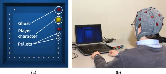
A BCI can also be used to measure a mental state. For instance, George et al. have designed a system allowing to measure the level of concentration and relaxation [George et al., 2011]. This concentration level can be deduced with the help of ratios or combinations of the alpha, beta and theta rhythms [Lin and John,2006;Mühl et al.,2010;Hjelm and Browall,2000]. Another method uses machine learning techniques to classify these mental states [Hamadicharef et al.,2009]. George et al. have compared these two methods and have found that the machine learning technique had a better performance [George et al.,2011]. In addition, they have also determined the best EEG electrode amount and head placement. Their user study was based on a simple game-like 2D environment, where participants were moving a plane up or down depending on their mental state (seeFigure 1.7, (a) and (b)).
(a) Relaxation mental state. (b) Concentration mental state.
Figure 1.7 – A simple 2D application used to display the concentration/relaxation mental state de-tected through a BCI [George et al.,2011].
1.2 Combining brain-computer interfaces and other user inputs
The combination of a bracomputer interface with other inputs or another bracomputer in-terface is often called a “hybrid brain-computer inin-terface”. Hybrid BCIs have been introduced by Pfurtscheller et al.: “Nowadays, everybody knows what a hybrid car is. A hybrid car normally has two engines to enhance energy efficiency and reduce CO2output. Similarly, a hybrid BCI is com-posed of two BCIs, or at least one BCI and another system” [Pfurtscheller,2010]. A hybrid BCI canCombining brain-computer interfaces and other user inputs
be seen as a combination of devices and paradigms that contains at least one BCI device. In this manuscript we will use the term “component” as a device or a paradigm contained in a hybrid BCI system.
Components of a hybrid BCI system can operate sequentially or simultaneously. Figure 1.8 shows two hybrid BCIs operating simultaneously (B and C) and five operating sequentially (A, D-G). The sequential processing shows the “switch” and the “selection” modes, that could be used to trigger the activity of the second component or make a choice between two other components, respectively. The “fusion” operation is here represented by a “+” sign, showing that the information gathered by these components is “added” to obtain the resulting output. This figure also illustrates the variety of components in a hybrid BCI: a non-EEG BCI device is used in E, an electrocardiography device in B and D, and an eye-tracking device in G. All these devices will be described in the following sections.
Figure 1.8 – Examples of hybrid BCI components operating sequentially or simultaneously [Pfurtscheller,2010].
1.2.1 Main concepts behind hybrid brain-computer interfaces
A hybrid brain-computer interface is composed of multiple elements which are associated together to form a system. When BCIs are associated together they are usually “active” as opposed to “pas-sive”, that is, users are actively sending commands through the interface rather than being “mon-itored” by it. Most BCI setups are considered active in the sense that the user has to deliberately control her brain activity in order to trigger an event or fulfill an objective [George and Lécuyer,
2010]. Active BCIs have a low data transfer rate, usually under 25 bits per minute [Wolpaw et al.,
2002]. Passive BCIs are frequently used in combination with other inputs, and, as such, are fre-quently part of a hybrid BCI.
The first part of this section proposes an overview of the nature of the elements composing the hybrid BCI: “mixed” (a BCI combined with other inputs) or “pure” (only BCIs). The second part of this section will deal with the sequentiality of the data processing, e.g. if the data coming from one component is processed before or at the same time as another one.
1.2.1.1 Mixed or pure hybrid brain-computer interfaces
Hybrid brain computer interface systems can be classified in two categories, depending on whether they include only BCI devices or a combination of BCI and non-BCI devices. Hybrid BCI systems using only BCI devices with single or multiple paradigms will be called “pure hybrid BCI” (see
Figure 1.9, (a) and (b)) whereas systems using any non-BCI device will be called “mixed hybrid BCI” (seeFigure 1.9, (c)). Section1.2.2lists the most common non-BCI devices used in mixed hybrid BCI systems. EEG (P300) EEG (SSVEP) hBCI (a) EEG (P300) NIRS (P300) hBCI (b) EEG (P300) ECG hBCI EOG (c)
Figure 1.9 – Three possible combinations of components within hybrid BCI systems. (a) Pure hybrid BCI system using two EEG devices with different paradigms. (b) Pure hybrid BCI system making use of two BCI devices with the same paradigm. (c) Mixed hybrid BCI system using one BCI device and two non-BCI devices.
Mixed hybrid BCI systems tend to use electrooculography, electromyography and electrocar-diography together with other components (see Section1.2.2).
1.2.1.2 Sequential or simultaneous processing
Hybrid brain computer interfaces can process incoming data sequentially or simultaneously. Se-quential processing means that the data gathered from one component will be used before the data retrieved from other components. This has been illustrated by the “brain switch”, where one component is employed to trigger the data processing of another component [Pfurtscheller,2010]. Pfurtscheller et al. used this brain switch to control an orthosis [Pfurtscheller et al.,2010]. A SSVEP paradigm is used with LEDs to let the user choose which part of the orthosis she wants to move. The motor imagery paradigm is then used to effectively move the orthosis. This reduces the amount of false positives and illustrates one use of a “brain switch”.
Simultaneous processing means that all the data sent by each component is processed at the same time. Li et al. employed this processing method to control a 2D cursor [Li et al.,2010]. Vertical movement was done with the help of the P300 paradigm while horizontal movement was done using motor imagery. Both components interacted on the system at the same time.
1.2.2 Most commonly used input devices in hybrid brain-computer interfaces
Some devices are frequently used in combination with brain-computer interfaces. The following section lists these devices and provides some examples of previous work.
• Eye trackers: a first kind of eye tracker, electrooculography, measures the steady electric potential field emitted by eyes, seen as dipoles. The cornea would be the positive pole and the retina the negative pole [Bulling et al.,2008]. Eye movement can be measured by capturing the electric potential field by placing electrodes that will receive a positive or negative signal amplitude, depending on the position of the retina and the cornea. Figure 1.10 shows an electrooculography device. Other types of eye trackers use a special type of contact lens or a video camera [Young and Sheena,1975]. Eye trackers can be used to measure movements and various events like blinking, saccades and fixations. It has been used with a BCI to allow disabled people to control robots [Wijesoma et al.,2005] or to target an element on a screen such as in a speller.
• Electromyography: electromyography measures the electrical activity emitted during mus-cular activity and can be placed on the surface of the skin or within the muscle. Electromyog-raphy is used to retrieve data about muscular activity level and duration [Clancy et al.,2002].
Combining brain-computer interfaces and other user inputs
Figure 1.10shows an electromyography device placed on a subject. The role of electromyog-raphy devices in BCIs systems is often to measure the muscle activity during a motor imagery or motor execution task to improve accuracy.
(a) (b)
Figure 1.10 – (a) Electromyography device placed on a user [Piitulainen et al.,2012]. (b) Electroocu-lography device [Bulling et al.,2008].
• Electrocardiography: electrocardiography uses electrodes usually placed on the chest to monitor heart activity [Opie,2004]. It is used to measure the heart beat rate and regularity, and allows diagnosis of heart damage or abnormalities. One example of electrocardiography usage in hybrid BCI systems is the measurement of effort [Pfurtscheller,2010]. This effort measurement can then be used to trigger a BCI devices on or off. This system helps preventing false positives.
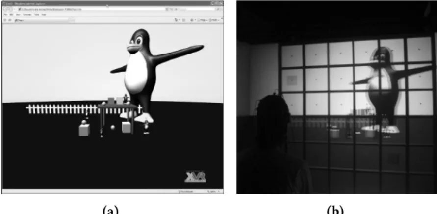
• Other input devices: mice, keyboards, and joysticks are also sometimes used with a BCI. A hybrid setup proposed by Leeb et al. uses a joystick to control the movement of a penguin on a slope while a BCI system is employed to trigger jumps [Leeb et al.,2013]. Kreilinger et al. used a joystick as a device which performance could decrease over time to simulate the users tiredness [Kreilinger et al.,2012]. The user automatically switched from one device to the other depending on a “device score”.
1.2.3 Representative examples of hybrid brain-computer interfaces
The following section describes a selection of hybrid BCI setups, depending on the nature of their components: pure hybrid BCIs (including only BCI devices and paradigms) and mixed hybrid BCIs (including non-BCI devices).
1.2.3.1 Pure hybrid brain-computer interfaces
This section describes a selection of setups including BCI devices and/or paradigms. In these setups, only BCIs are used to actively record commands or passively gather brain activity data from users.
Combining motor imagery and P300: the motor imagery paradigm has been combined with the P300 paradigm in a system designed by Riechmann et al. [Riechmann et al.,2011]. This setup proposes a parallel and asynchronous system including both paradigms. The level of false positives was measured while subjects had to use one paradigm or the other. One target was presented to the user: one of five P300 symbols or one of two motor imagery directions (left or right).
Combining motor imagery and SSVEP: a system integrating motor imagery with SSVEP has been proposed by Pfurtscheller et al. [Pfurtscheller et al.,2010]. This setup allowed users to operate a four-step hand orthosis with the help of the SSVEP and the motor imagery paradigms. Two LEDs were placed on the orthosis (seeFigure 1.11), one flickering at 8 Hz and the other at 13 Hz. These two LEDs were used by the user to choose which part of the orthosis he wanted to open or close. Motor imagery was then employed to execute the task. Each user executed four different tasks. The first one allowed the user to open or close the orthosis using only the SSVEP paradigm. The second task used a cue on a computer screen to do the training required by the motor imagery paradigm, users were asked to execute fast feet movements. The third one consisted in making use of both paradigms to operate the orthosis in a self-paced way. The last task consisted in using only the SSVEP paradigm and served as a control setup. Only two EEG channels were used, one on the motor cortex and the other on the visual cortex. This hybrid system showed a reduced amount of false positives compared to the continuous use of event related synchronization only.
Figure 1.11 – A hand orthosis driven using a BCI. The SSVEP paradigm could be used to choose which part of the orthosis should be activated and the motor imagery paradigm could trigger the movement execution. (A), (B), (C) and (D) show four different steps for opening the orthosis [Pfurtscheller et al., 2010].
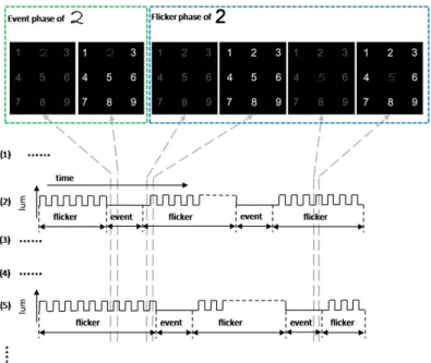
Combining P300 and SSVEP: the combination of P300 and SSVEP has been proposed by Xu et al. [Xu et al.,2013]. This setup aimed at improving the performance of a P300 speller by means of hybridization of SSVEP and P300 (seeFigure 1.12). Twelve subjects performed an offline spelling with the two approaches. No training has been done beforehand. Six of the subjects used the hybrid configuration first while the other six started by using the P300 paradigm only. A 3x3 matrix was used, showing numbers from 1 to 9 on a computer screen. In the hybrid system, the characters were highlighted in a random sequence. The size and font of the characters were changed to trigger a P300 and flickering was used to trigger a SSVEP reaction. Results showed that spelling performances were largely improved by using the hybrid system.
1.2.3.2 Mixed hybrid brain-computer interfaces
This section describes a selection of setups including BCI paradigms combined with non-BCI devices.
Combining motor imagery with electromyography, eye tracking, or electrocardiography: Leeb et al. combined EEG and electromyographic data, allowing partly paralyzed persons to use their residual muscular activity together with motor execution or motor imagery (seeFigure 1.13) [Leeb et al., 2011]. In the cases when paralysis is only partial, some residual muscular activity
Combining brain-computer interfaces and other user inputs
Figure 1.12 – Time evolution of a P300 speller grid used with both the P300 and the SSVEP paradigms. An “Event phase” is employed to trigger a P300 activity while a “Flicker phase” is used to trigger a SSVEP event [Xu et al.,2013].
can still be used. Each trial consisted in fixating a cross on a computer screen for 3 seconds then a cue for 5 seconds, indicating on which hand motor execution should be performed. EEG and electromyography were recorded at the same time and the fusion of both was done using equally balanced weight and a naive Bayesian technique. The control of this BCI was done using each component or both of them. This setup showed that control can be achieved even when the user is tired. Classification results for the EEG component alone were 73%, 87% for electromyography and 91% for the fusion of both.
Figure 1.13 – A person wearing an EEG cap and electromyography electrodes. The diagram shows the different phases of processing and fusion needed for each component of the hybrid BCI [Leeb et al., 2011].
Eye tracking devices can be used to select letters or words. A combination of this device with motor imagery or motor execution has been proposed by Yong et al. [Yong et al.,2011]. This setup used an eye tracking device and motor imagery (or motor execution) to select letters or words (see Figure 1.14). The user had to maintain her gaze on the word or letter she wanted to write during a certain amount of time. The system also had a “sleep mode” that was activated when no letter or word was gazed to reduce the amount of false positives. The classifier used to detect the attempted hand extension was also adaptively updated. This setup was using a program called Dynamic Key-board that allowed the user to enter text by pressing large buttons and had also a word prediction feature.
Figure 1.14 – A person wearing an EEG cap and electrooculography electrodes, using the eye tracker to point a position on the screen and an attempted hand extension (motor execution or motor imagery, depending on the user being able to move her hands) to simulate a mouse click [Yong et al.,2011].
Combining motor imagery with electrocardiography, Shahid et al. proposed to measure if a classification performance could be noticed [Shahid et al.,2011]. Multiple trials were done, each of them lasting 12 seconds: 6 seconds in a relaxed state and 6 seconds where a directional arrow was shown indicating that a left foot or left hand motor imagery task had to be executed. A third symbol represented a rest state.Figure 1.15shows a block diagram of the processing technique. Two different analyses were performed on the results of a classification between a hand motor imagery task and a rest task. The first one, measuring the average heart rate during a motor imagery task, showed that a 10% heart rate increase could be noticed in that case. The second analysis showed that the simultaneous use of both devices led to an average classification accuracy of 92%, whereas EEG alone produced a classification accuracy of 73%. The fusion or electrocardiography and EEG features enhanced the motor imagery classification in both training and evaluation thanks to the reduced number of false positives.
Figure 1.15 – A block diagram of a system combining motor imagery and electrocardiography to measure a possible classification performance improvement [Shahid et al.,2011].
Combining P300 and electrooculography: a system designed by Postelnicu et al. used a mod-ified stimulus presentation paradigm called the “Half Checker Board Paradigm” to improve the spelling speed thanks to the P300 paradigm and an electrooculography device [Postelnicu and Ta-laba,2013]. A 8x9 matrix was divided in areas selected with the help of electrooculography (see Figure 1.16). These areas were composed of multiple characters and symbols that were randomly highlighted. The characters were selected using EEG. An electrooculography calibration phase was required every 2 characters entered. The users had to write a 13 characters long text for calibration and a 16 characters long text for the evaluation. A reduction in the time needed to spell one char-acter was observed when using the half checkerboard paradigm, resulting in a more effective P300 paradigm.
Combining brain-computer interfaces and virtual/augmented reality
(a) (b)
Figure 1.16 – A character matrix used for spelling. The matrix (a) is divided into areas (b) that can be selected with the help of an electrooculography device while character selection is performed using the P300 paradigm [Postelnicu and Talaba,2013].
1.2.4 Conclusion
In this section we have provided an overview of hybrid brain-computer interfaces, how its BCI components can be characterized, how they can be combined depending on their nature, and how they can be processed in time (sequentially or in parallel). Some examples of commonly used in-put devices within a hybrid BCI have been presented, as well as representative examples of hybrid BCI systems. In the context of this thesis, hybrid BCIs could provide a way to interact with VR: a BCI could be combined with classical VR input devices. The next section gives an overview of the association between a BCI and a particular output: virtual or augmented reality displays.
1.3 Combining brain-computer interfaces and virtual/augmented
reality
Brain-computer interfaces and virtual/augmented reality are two different research topics that have been studied for many decades. The combination of both, however, is relatively recent [Lécuyer et al.,2008;Bayliss and Ballard,2000]. This combination can be seen from two different perspectives [Lotte et al.,2013a]. First, VR can be seen as a testbed for BCI systems and studies [Bayliss and Ballard,2000]. Second, a BCI can be used as a novel input device for VR systems [Edlinger et al.,
2011]. Video-games are one of these VR systems. Literature on the feasibility of associating a BCI and a video-game has increased during the last decade [Lécuyer et al.,2008;Nijholt et al.,2009]. Similarly, the association of BCI with AR has also gained some interest [Escolano et al.,2012;Kansaku,2011;
Scherer et al.,2011], but AR is less studied and more recent. This section provides an overview of the use of BCIs with both VR and AR.
1.3.1 Brain-computer interfaces and virtual reality
1.3.1.1 Representative examples of virtual reality applications using a brain-computer interface
In this section we present a selection of examples of virtual reality applications making of use a brain-computer interface. The organization of these examples is inspired by the recent work done by Lotte et al. [Lotte et al.,2013a]. Indeed, concerning the VR interaction tasks defined by Bowman et al. and BCI paradigms, they observe that “each BCI paradigm is more or less suitable for each category of interaction task. For instance, motor imagery and SSVEP-based BCIs seem more suitable for navigation tasks and possibly object manipulation because they can issue commands continuously
and potentially in a self-paced way. On the other hand, a P300-based BCI let the user pick one item among a list of usually at least four, such a command being issued in a discrete and synchronous way. For this reason, they are more suitable for object selection tasks” [Lotte et al.,2013a]. This underlines the importance of the choice of the BCI paradigm combined with the VR system. The following examples are organized depending on the BCI paradigm they are using. The interested reader can refer to the following book chapter: [Lotte et al.,2013a] and the following articles: [Lécuyer et al.,
2008;Lecuyer et al.,2013] for a more complete survey and overview of previous work on BCI and VR.
Motor imagery: one possible use for motor imagery within a virtual environment is for navi-gation purposes. Ron-Angevin et al. have designed a system where users could send four commands: move forward, move backwards, turn left, and turn right [Ron-Angevin et al.,2009]. Their interface comprised a circle, surrounded by symbols representing these commands (seeFigure 1.17).
Figure 1.17 – Interface used for navigation in a virtual environment, comprising a circle and a rotating bar used to select the command to be run. The motor imagery paradigm was used to trigger the command selection [Ron-Angevin et al.,2009].
A bar was continuously rotating in its center, and users could control the length of this bar with the help of two motor imagery tasks. Commands were run each time the bar would reach the corresponding command symbol. This system has been later extended by Velasco-Aĺvarez et al. [Velasco-Álvarez et al.,2010]. In their setup, users could navigate a wheelchair in a virtual environ-ment using a similar “command circle”, but two steps were required to run a command: select it, and choose the amplitude of the movement. This choice was achieved thanks to the same rotating bar: the length of the bar represented the amplitude. While the previous commands can be seen as being “low-level”, Lotte et al. proposed “high-level” commands as an alternative [Lotte et al.,2010]. In their system, users could navigate within a virtual museum with the help of points of interest that were generated automatically depending on the geometry of the virtual environment. Users had to select a destination instead of issuing basic commands like moving in a straight line or rotating (see Figure 1.18).
Combining brain-computer interfaces and virtual/augmented reality
Figure 1.18 – Virtual museum navigation based on a BCI and associated user interface proposed in Lotte et al. [Lotte et al.,2010].
SSVEP: making use of SSVEP in a VR environment was first proposed by Lalor et al. [Lalor et al.,2005]. Their system was composed of a 3D animated character that had to walk on a tightrope within a virtual environment. The movement of the character was conditioned by the output of the BCI. Users had to look at one of two checkerboards placed on each side of the screen so that the character would keep its balance (seeFigure 1.19). A user study showed that the visually rich environment allowed for a reliable control using SSVEP.
Figure 1.19 – Mind-Balance game showing the use of a SSVEP-based BCI with a virtual environment [Lalor et al.,2005].
An ecological way of using SSVEP in a virtual world has been shown by Legény et al. [Legény et al.,2011]. In this case the user had to focus on butterflies to navigate in a virtual forest (see Figure 1.20). Each butterfly was flickering at a specific frequency and its antennae were used to represent the intensity of the command as detected by the BCI.
(a) (b)
Figure 1.20 – Navigation in a virtual environment using SSVEP. (a) Virtual environment with a path that had to be followed. (b) Three butterflies used as flickering targets for the SSVEP paradigm [Legény et al.,2011].
P300: an illustration of P300 usage in a VR environment was proposed by Donnerer et al. [Donnerer and Steed,2010]. Their setup included a Cave Automatic Virtual Environment (CAVE)-like environment where various 3D objects were displayed. A selection task was asked from the users. Two variants were tested: selecting a blinking object or selecting a cell from a grid overlayed on the whole scene (seeFigure 1.21). A user study, performed with this setup, showed that both selection tasks could be performed efficiently within a virtual environment.
(a) (b)
Figure 1.21 – Selection of objects from a scene or a cell from a grid based on P300 in a CAVE. (a) Object selection. One of the cubes is blinking. (b) Cell selection [Donnerer and Steed,2010].
Concentration/relaxation: the association of the concentration/relaxation BCI paradigm with VR has been described by Lécuyer et al. [Lecuyer et al.,2013] in the form of a system called “Virtual Dagobah”. Their system used a CAVE environment to display a well known scenery from the movie “The Empire Strikes Back” where Luke Skywalker trains to become a Jedi. Users were wearing an EEG headset and could lift various objects such as a helmet, a robot, or a spaceship by performing a mental concentration task (seeFigure 1.22). Each object had a particular weight which proportion-ally increased the difficulty and the concentration level required to lift it.
Considering the previous systems, we can observe that some paradigms have been used for some particular VR tasks, meaning that they may be more appropriate for these. According to Lotte et al., SSVEP and P300 were mostly used in previous work for selection or manipulation tasks because they enable the selection of objects by paying attention to them. Motor imagery and SSVEP seems more natural for navigation or manipulation tasks because they can issue commands continuously.
Combining brain-computer interfaces and virtual/augmented reality
Figure 1.22 – Cave Automatic Virtual Environment (CAVE) environment application using the con-centration/relaxation BCI paradigm to lift objects by concentration [George,2012].
1.3.1.2 Passive brain-computer interfaces and virtual reality
Passive brain-computer interfaces are used to monitor the brain activity of users while they are performing a task. A passive BCI can be used to adapt certain parts of a virtual environment, for in-stance changing the difficulty of a VR task when a high cognitive activity is detected. The following systems have associated a passive BCI with VR.
The “Alpha WoW” system integrated a passive BCI to the “World of Warcraft” video-game [ Ni-jholt et al.,2009]. The BCI was used to evaluate the players stress level, and changed accordingly the appearance of their avatar from an elf to a bear (seeFigure 1.23).
Figure 1.23 – “Alpha WoW” application where a user avatar can transform itself in a bear depending on the users stress level [Nijholt et al.,2009].
The “Bacteria Hunt” system uses a passive BCI to adapt the controllability of a game-like ap-plication where users control an amoeba and have to eat bacteria moving on a field [Mühl et al.,
2010]. The passive BCI was used to measure the players relaxation level using the alpha frequency band. Movement of the players avatar was done with the help of conventional input devices such as a keyboard and a mouse while an active SSVEP-type BCI was used to trigger the “eating phase” of the amoeba.
1.3.1.3 Hybrid brain-computer interface and virtual reality
Control within a virtual environment can be characterized by the tasks that users can perform within the virtual environment. Bowman proposed four tasks: selection of virtual objects, manipulation of these objects, navigation in the environment, and control of the application [Bowman,1999]. Each one of these tasks could be performed using an element composing a hybrid BCI. This section pro-poses a selection of applications combining a hybrid BCI with a virtual environment and describes which VR task was performed with each hybrid BCI element.
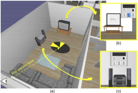
Combining P300 and SSVEP: controlling home automation devices has been achieved by Edlinger et al. by combining P300 with SSVEP in a virtual environment (seeFigure 1.24) [Edlinger et al.,2011]. The SSVEP paradigm was used to enable/disable the detection of P300 events. The SSVEP system used flickering LEDs or flickering symbols on a computer screen. There were 7 different control masks: light, music, phone, temperature, TV, move and go to. This system showed that the hybrid use of the P300 and SSVEP paradigms to select options from a panel presented a very good level of reliability and accuracy.
(a) (b)
Figure 1.24 – Home automation in VR driven by P300 and SSVEP. (a) A TV control mask, selection was achieved using the P300 paradigm. (b) Person issuing a command in the virtual environment [Edlinger et al.,2011].
Combining motor imagery and P300: the motor imagery paradigm has been combined with the P300 paradigm to move and to control objects in a virtual environment (seeFigure 1.25) [Su et al.,2011]. Motor imagery was used to move around in several rooms by allowing the user to imagine left or right hand movements. The P300 paradigm was used to operate virtual objects that were present in each room. A state switch was used to determine which paradigm should be detected. The control state was activated when the user was moving close to an object that could be controlled. The navigation state could be reached again by pressing a button. This system showed that the combination of motor imagery with the P300 paradigm could be successful in terms of BCI performance.
1.3.1.4 Motor activity, brain-computer interfaces, and virtual reality
Using a brain-computer interface while performing a motor activity such as using a virtual reality device carries a risk of producing artifacts in the EEG signal [De Clercq et al.,2006].
Motor activity can be triggered by the use of common input devices like a mouse or a joystick. The combined use of BCIs with other input devices such as a mouse has been rarely studied in BCI or VR scientific communities. But a recent example of this is an application called “Bacteria Hunt” in which the controllability of a mouse was impaired proportionally to the level of alpha band power, which was in this application correlated to relaxed wakefulness [Mühl et al.,2010]. In “AlphaWow”, which is based on the video-game World of Warcraft, the user’s avatar transforms itself from an elf to a bear according to the measured level of alpha activity [Nijholt et al.,2009]. However, the authors of these studies did not specifically compare the use of their setup with and without the manipulation of the mouse.
In the context of virtual environments, two other representative studies reported on setups com-bining a joystick and BCI. First, Kreilinger et al. proposed to switch alternatively from joystick to BCI to provide a continuous source of reliable control [Kreilinger et al.,2012]. Both devices were not used simultaneously. The VR entertaining application consisted in controlling a car to collect
Combining brain-computer interfaces and virtual/augmented reality
Figure 1.25 – A virtual environment where various objects can be controlled with the help of motor imagery and P300. (a) up-down view of one room of the virtual environment. (b) a TV object than can be controlled using the P300 paradigm. (c) a stereo object that can be controlled. The three numbered buttons correspond to channels or songs that can be selected. The circle button triggers the exit of the control state while the square button stops the playing of a channel or song [Su et al.,2011].
coins and avoid obstacles. A reliability score was computed for both devices, allowing the selection of the most reliable device at any time. The switching between BCI and joystick was found to im-prove the user experience, allowing participants to control the car even after losing control of one of the devices. Combining motor imagery with a joystick, Leeb et al. proposed a hybrid BCI system using a virtual environment and consisting of a track and a penguin sliding on it [Leeb et al.,2013]. A mountainous background was displayed to further enhance the users immersivity. A motor im-agery paradigm was used to make the penguin jump to catch one of multiple fish laying on the track. While the BCI task was the primary task, users also had to perform a secondary task: controlling the trajectory of the penguin thanks to a joystick. The environment was displayed within a CAVE system. The virtual environment of the CAVE system increased the motivation of the users to get a better score and thus to improve their performance. This hybrid interaction scheme was found globally efficient and well appreciated by the participants. However, the mutual influence of motor and mental activities is not the main purpose of this article.
(a) (b)
Figure 1.26 – A game-like virtual environment where users had to control a penguin by using a joystick and make it jump thanks to a BCI. (a) A user in front of the virtual environment. (b) Data gathered and processed during a virtual jump attempt [Leeb et al.,2013].
1.3.2 Neurofeedback and virtual reality
The last decade has seen an increase of interest in using VR as a motivating feedback for neurofeed-back systems. According to Heinrich et al., neurofeedneurofeed-back can be defined as “a form of behavioural training aimed at developing skills for self-regulation of brain activity” [Heinrich et al.,2007]. For this self-regulation to operate, users have to get a real-time feedback about their brain activity. While a BCI is a way to send data to a computer, neurofeedback proposes a loop of information between the computer and the user. For example, users could be sitting in front of a computer screen, looking at a gauge representing their brain activity in a particular frequency band [Neuper and Pfurtscheller,
2010]. Their objective would then be to maximize this activity by performing a cognitive task re-lated to this frequency band. Users would then learn to elicit this type of brain activity and see their performance improve over time. Neurofeedback has been used to help curing epilepsy, anxi-ety, and alcoholism [Hammond,2007], and provides an alternative to stimulant medication for some treatments like attention deficit hyperactivity disorder [Fuchs et al.,2003].
Virtual reality can be used to improve neurofeedback results for attention deficits, as shown by Cho et al. [Cho et al.,2004]. They have designed a virtual classroom where participants were asked to perform a continuous performance task, which “provides measurements of the ability to respond and pay attention” [Cho et al.,2004].
It has also been shown that using a virtual environment in neurofeedback systems can improve the performance of the BCI (and thus neurofeedback performance) by providing additional infor-mation about the underlying brain activity [Lotte et al.,2013b].
1.3.3 Brain-computer interfaces and augmented reality
The idea of combining a brain-computer interface with augmented reality has been proposed by Navarro [Navarro,2004]. The purpose of the author was to find a way to incorporate BCIs “into daily life” by designing a “wearable BCI”. According to her, the limitations of BCI systems were “slow users response times, excessive error rates, high cost, actual appearance and long initial training periods”. Based on the results of the BCI Competition at Graz University of Technology in 2003 [Blankertz et al.,2004], she suggested the use of the P300 paradigm for its low error rate. Acknowledging a possible issue with the selection time, she also mentioned the SSVEP paradigm as an alternative. The author expressed the issue of using a BCI in a highly changing environment. Navarro thus proposed the use of AR as a way to obtain a “transparent coupling” of the BCI in the varying environments.
The following sections will present the systems including a BCI and AR depending on their main objective: the manipulation of real objects, the manipulation of virtual objects, and the visualization and analysis of brain activity. The systems are then organized depending on the BCI paradigm they are using: motor imagery, SSVEP, or P300.
1.3.3.1 Manipulation of real objects
Several systems combining augmented reality and a brain-computer interface aim at manipulating mechanical devices like robots or mechanical arms, as well as other electronic devices like electrical home appliances.
Motor imagery: making use of dry EEG electrodes, Lampe et al. proposed a setup where users were manipulating a robotic arm using a BCI [Lampe et al.,2014]. Users were controlling the arm from another location. The data coming from the BCI and image data coming from a camera placed on the arm were transfered through the Internet. They used a neural network classification system to obtain commands from the BCI. These commands were sent through an AR interface. A reaching-grasping task was carried out. A user study has shown that both tasks could be performed whith
![Figure 1.7 – A simple 2D application used to display the concentration/relaxation mental state de- de-tected through a BCI [George et al., 2011].](https://thumb-eu.123doks.com/thumbv2/123doknet/11596420.299048/26.892.161.758.677.902/figure-simple-application-display-concentration-relaxation-mental-george.webp)
![Figure 1.8 – Examples of hybrid BCI components operating sequentially or simultaneously [Pfurtscheller, 2010].](https://thumb-eu.123doks.com/thumbv2/123doknet/11596420.299048/27.892.139.735.384.653/figure-examples-hybrid-components-operating-sequentially-simultaneously-pfurtscheller.webp)
![Figure 1.19 – Mind-Balance game showing the use of a SSVEP-based BCI with a virtual environment [Lalor et al., 2005].](https://thumb-eu.123doks.com/thumbv2/123doknet/11596420.299048/35.892.221.652.678.997/figure-mind-balance-showing-ssvep-virtual-environment-lalor.webp)
![Figure 1.32 – An AR system allowing users to look at various appliances and sending commands to them using a BCI [Kansaku, 2011].](https://thumb-eu.123doks.com/thumbv2/123doknet/11596420.299048/43.892.286.583.615.931/figure-allowing-users-various-appliances-sending-commands-kansaku.webp)
![Figure 1.33 – Real hands overlaid by virtual hands that are controlled using a BCI [Chin et al., 2010].](https://thumb-eu.123doks.com/thumbv2/123doknet/11596420.299048/44.892.157.757.251.480/figure-real-hands-overlaid-virtual-hands-controlled-using.webp)