Pépite | Modélisation tridimensionnelle pour l'analyse de la stabilité des carrières souterraines à long terme
216
0
0
Texte intégral
(2) Thèse de Faten Rafeh, Lille 1, 2015. © 2015 Tous droits réservés.. doc.univ-lille1.fr.
(3) Thèse de Faten Rafeh, Lille 1, 2015. ACKNOWLEDGEMENT The work in this thesis has been carried out at the Laboratory of Civil and GeoEnvironmental Engineering LGCgE at Polytech’Lille, University of Lille 1 under the supervision of Professor Hussein Mroueh and the assistance of Dr. Sébastien Burlon. This work, which provides a long term stability assessment of the shallow underground cavities identified in Lille and North France consists a part of the Plan of Prevention of Risks PPR and particularly the National Plan of Cavities PNC held in France. It is performed in collaboration with the City of Lille, Service of Urban and Health Risks, as well as the specialized engineering company for geotechnical research works Sémofi. Foremost, I would like to thank my supervisor, Professor Hussein Mroueh, for the trust he had in me from the very beginning. Both, his continuous support and guidance all along those 3 years have been a key to this achievement. My thankfulness is also owed to Doctor Sébastien Burlon for believing in this work, and thereafter for the fruitful discussions we have been through during the last 2 years. His patience, despite the complaints that I am a bit stubborn, has been priceless too. I am also grateful for the people who have contributed to this work by non-rewardable confidence and support. Thanks to the head of the Service of Urban and Sanitary Risks at the City of Lille, Mr. Gaëten Cheppe. Thanks to the head of Sémofi, Mr. Jean Marc Gallet de Saint Aurin. And my sincere thankfulness also goes to Madame Géraldine Berrehouc, representing both the City of Lille and Sémofi, for her serious engagement and enthusiasm towards this project. I would like to thank my PhD committee for accepting to be a part of this achievement by reading, reporting, and examining my work at one hand, and for crossing distances to participate in and chair the jury on the day of my PhD defence. Thanks to Professors Anne Pantet, Véronique Merrien-Soukatchoff, Eric Vincens, Jianfu Shao, and Isam Shahrour. Three years at Polytech’Lille were not only about making a PhD; they were also about making a new family of friends and colleagues with whom I’ve shared the ups and downs, in and out of the lab. I would like to express my gratitude to all my PhD fellows at LGCgE, those who are already done with their PhDs, and those who are on the way. Besides, I would like to thank my colleagues of lecturers and professors at Lille 1 University with whom I’ve. i © 2015 Tous droits réservés.. doc.univ-lille1.fr.
(4) Thèse de Faten Rafeh, Lille 1, 2015. shared the hassles, as well as joyful moments of teaching at the department of civil and mechanical engineering. I can’t but express my heartfelt and profound thankfulness to all my friends in Lebanon, in France, and elsewhere for all the encouragement and enjoyment they’ve got into my life. This has been necessary and non-doubtfully treasured. Last but not least, I am indebted to my family, my dad and mom and my 2 brothers; without you standing by me, without you believing in me, and without you giving me all, I couldn’t have been me, I couldn’t have struggled for further achievements, and I couldn’t have succeeded on and on. This PhD is dedicated to you. Thank you!. ii © 2015 Tous droits réservés.. doc.univ-lille1.fr.
(5) Thèse de Faten Rafeh, Lille 1, 2015. ABSTRACT The presence of hundreds of unexploited underground quarries in the region of North France regarding their close proximity to urbanized areas, poses serious problems in terms of the security of both people and constructions on one hand, and induces a strong constraint against the planning and urban development on the other hand. In this framework, this thesis presents a numerical analysis of the stability of underground cavities excavated decades ago in the chalk substratum of North France. It aims to provide a complementary understanding for the geological investigations and observations carried out. These latter have shown that two stratigraphic joints are present in the chalk layers. Besides, fractures developing due to the progressive degradation of chalk are observed. Hence, the first target in this thesis is to account for the anisotropic behaviour induced due to the presence of joints. Anisotropy, whether inherent or induced, intrinsically affects the strength, and the strain behaviour of the chalk mass especially at shallow depths (which represents our case study) where confining stresses are low. Hence, a constitutive law accounting for the anisotropic behaviour is studied by considering several mechanisms of plasticity. Next, a three dimensional numerical modelling of the excavation is performed and a stability analysis which depends on the conventional shear strength reduction procedure is integrated. The influence of joints is described in details and the strain and failure mechanisms are also analysed. This provides a better understanding of the mechanical behaviour of the jointed underground cavities under study. Time effects and degradation mechanisms induced in the presence of different aggravating factors have an important influence on the stability. A time-dependentdegradation model is developed. It is used to model the time-dependent deformation and failure mechanisms and to assess the long term stability of these cavities. A comparison between the stability analysis achieved using conventional shear reduction method, and that using the developed non-homogeneous time-dependent degradation model which depends on the accumulation of plastic strains in the continuum is done. At the end, for the direct preliminary assessment of the stability of identified cavities, a parametric stability study was. iii © 2015 Tous droits réservés.. doc.univ-lille1.fr.
(6) Thèse de Faten Rafeh, Lille 1, 2015. conducted and extrapolated formulae as well as abacuses were developed. This helps in the preliminary estimation of stability state of the investigated quarries.. KEY WORDS : UNDERGROUND CAVITIES , CHALK, JOINTS, STABILITY, DEGRADATION. iv © 2015 Tous droits réservés.. doc.univ-lille1.fr.
(7) Thèse de Faten Rafeh, Lille 1, 2015. RESUME La présence de centaines de carrières souterraines abandonnées dans le nord de la France, à proximité de zones urbanisées, est à l’origine de problèmes importants touchant à la sécurité des personnes et des constructions, d’une part, et à l’élaboration de plans d’urbanisme d’autre part. Dans ce cadre, cette thèse présente l’analyse numérique de la stabilité de cavités souterraines creusées il y a des dizaines d’années dans la craie du nord de la France. Elle a pour objectif de proposer une approche complémentaire aux observations et investigations menées habituellement. Ces dernières permettent de savoir que la craie du nord de la France présente des familles de joints. Par ailleurs, la dégradation de la craie induit le développement d’autres plans de faiblesse. Ainsi, le premier objectif de la thèse est de rendre compte du comportement anisotrope induit par la présence de ces joints. Cette anisotropie, induite ou intrinsèque, affecte le comportement de la craie en termes de déformation et de résistance. En particulier, à faible profondeur (ce qui est le cas ici) où les contraintes de confinement sont faibles, le comportement de la craie est contrôlé par des phénomènes de glissement le long des joints et des déformations de cisaillement peuvent s’accumuler jusqu’à induire des ruptures et des effondrements. Une loi de comportement rendant compte de ce comportement anisotrope est étudiée en considérant différents mécanismes de plasticité. Une modélisation numérique tridimensionnelle d’une excavation est mise en œuvre et une analyse de la stabilité basée sur la procédure de réduction des paramètres de résistance au cisaillement est proposée. Le rôle de joints décrit en détail et les mécanismes de déformation et de rupture sont aussi analysés. Il ressort de cette analyse une meilleure compréhension du comportement des cavités souterraines et du rôle des joints. Les effets du temps et les mécanismes de dégradation induits par différents facteurs aggravants ont aussi un rôle important sur la stabilité. Une approche de dégradation dépendante du temps a été développée. Elle permet l’étude des mécanismes de déformation et de rupture en fonction du temps et l’estimation de la stabilité à long terme de la carrière. Une comparaison avec l’analyse de la stabilité mettant en œuvre la procédure conventionnelle de réduction des paramètres de cisaillement est. v © 2015 Tous droits réservés.. doc.univ-lille1.fr.
(8) Thèse de Faten Rafeh, Lille 1, 2015. réalisée. Enfin, pour l’étude préliminaire de la stabilité des carrières, des abaques sont proposés aux gestionnaires, scientifiques et donneurs d’ordre, et constituent un précieux outil d’aide à la décision concernant l’action à mener pour prévenir les risques.. MOTS CLEFS: CARRIERES SOUTERRAINES, CRAIE, JOINTS, STABILITE , DEGRADATION. vi © 2015 Tous droits réservés.. doc.univ-lille1.fr.
(9) Thèse de Faten Rafeh, Lille 1, 2015. TABLE OF CONTENTS. LIST OF FIGURES ............................................................................................................... xiii LIST OF TABLES ................................................................................................................. xix SYMBOLS ............................................................................................................................ xxi GENERAL INTRODUCTION .....................................................................................................1 CHAPTER ONE .......................................................................................................................7 UNDERGROUND CAVITIES: A DESCRIPTIVE OVERVIEW – STATE OF THE ART ..................7 1.1. Introduction .................................................................................................................7. 1.2 Why were underground cavities formed and where are they concentrated throughout the French territory? ................................................................................................8 1.3. How were the underground cavities excavated: Exploitation methods? ..................10. 1.3.1 Room-and-pillar exploitations ............................................................................... 10 1.3.2 Exploitations by holts-and-bottles ......................................................................... 11 1.3.3 Mixed type exploitations........................................................................................ 12 1.4. Common Risks ..........................................................................................................13. 1.4.1 Risks at the surface ................................................................................................ 13 1.4.1.1 The generalized collapse .................................................................................. 13 1.4.1.2 The collapse by localized rupture at pillars ..................................................... 14 1.4.1.3 The collapse localized by roof rupture/ sinkholes ........................................... 15 1.4.1.4 Subsidence or sagging...................................................................................... 16 1.4.1.5 Other types: Suffosions and Stripping ............................................................. 17. vii © 2015 Tous droits réservés.. doc.univ-lille1.fr.
(10) Thèse de Faten Rafeh, Lille 1, 2015. 1.4.2 Risks on people ...................................................................................................... 17 1.5 What are the regulations taken by concerned authorities towards this problematic? .............................................................................................................................18 1.6. Underground cavities of North France: Zones of concentration ..............................20. 1.7. Common failure mechanisms in room-and-pillar quarries .......................................22. 1.7.1 Rupture of the Pillars/ Supports ............................................................................. 23 1.7.1.1 Localized rupture of pillars .............................................................................. 23 1.7.1.2 Crushing by uniaxial compression ................................................................... 23 1.7.1.3 Buckling of pillars after rupture of connecting/stabilizing bridges ................. 23 1.7.1.4 Rupture by shear and traction/ tension............................................................. 24 1.7.2 Rupture of the Roof/ Slabs ..................................................................................... 24 1.7.2.1 Localized rupture of roof ................................................................................. 24 1.7.2.2 Rupture by flexure/ bending ............................................................................ 24 1.7.2.3 Rupture by shear .............................................................................................. 24 1.7.2.4 Rupture of wall/ Punching of walls ................................................................. 25 1.8. Studies accounting for the frequent failure mechanisms ..........................................25. 1.9. Geological context ....................................................................................................26. 1.10. Behaviour of Chalk ...................................................................................................29. 1.10.1.1 Stress-strain behaviour ..................................................................................... 30 1.10.1.2 Plastic yield mechanisms ................................................................................. 31 1.10.1.3 Effect of confining pressure on the behaviour of chalk ................................... 31 1.10.1.4 Brittle Failure ................................................................................................... 33 1.10.1.5 Discontinuities ................................................................................................. 34 1.10.1.6 Elastoplastic and elastoviscoplastic models..................................................... 35 1.10.2 Water dependent behaviour ................................................................................... 35 1.10.2.1 Mechanical Processes ...................................................................................... 37 1.10.2.2 Chemical Processes .......................................................................................... 41 1.10.3 Time dependent behaviour and effect of aggravating factors ................................ 43 1.10.3.1 Creep ................................................................................................................ 44 1.10.3.2 Weathering effect ............................................................................................. 46 1.10.3.3 Other external factors that motivate rupture .................................................... 47 1.11. What do we propose in this thesis? ...........................................................................49. 1.12. Conclusions ...............................................................................................................50. viii © 2015 Tous droits réservés.. doc.univ-lille1.fr.
(11) Thèse de Faten Rafeh, Lille 1, 2015. CHAPTER TWO.....................................................................................................................53 BEHAVIOUR OF CHALK: ACCOUNTING FOR THE EFFECT OF JOINTS ................................53 2.1. Introduction ...............................................................................................................53. 2.2. Constitutive law accounting for the presence of joints .............................................55. 2.2.1 Principles................................................................................................................ 55 2.2.2 Formulation ............................................................................................................ 55 2.2.3 Triaxial tests ........................................................................................................... 59 2.3 model. Comparison between the proposed joint model and another existing joint 60. 2.3.1 Ubiquitous joint model .......................................................................................... 61 2.3.1.1 Mesh refinement .............................................................................................. 61 2.3.1.2 Joint orientation: Joint dip direction (jdd) and joint dip angle (jdip) ............... 62 2.3.1.3 Influence of the strength properties of the weak plane .................................... 65 2.4. Comparison between existing and developed joint models ......................................66. 2.4.1 Ultimate resistance ................................................................................................. 66 2.4.2 Influence of the joint set orientation ...................................................................... 67 2.5. Results for chalk with the proposed joint model - Case 1: single joint set ...............68. 2.5.1 Joint orientation ..................................................................................................... 68 2.5.1.1 Ultimate resistance ........................................................................................... 68 2.5.1.2 Displacement distribution ................................................................................ 69 2.5.2 Relation between friction angle and the strength ................................................... 70 2.6. Results for chalk with the proposed joint model - Case 2: two joint sets .................71. 2.6.1 Ultimate resistance ................................................................................................. 72 2.6.2 Deformational behaviour ....................................................................................... 73 2.6.3 Displacement distribution ...................................................................................... 74 2.7. Conclusions ...............................................................................................................75. CHAPTER THREE .................................................................................................................77 3D NUMERICAL MODELLING OF STRAIN AND FAILURE MECHANISMS IN THE CHALK UNDERGROUND CAVITIES ..........................................................................................77 3.1. Introduction ...............................................................................................................77. 3.2 Algorithm for the joints shear strength reduction approach: Implementation in 3D FLAC 78 3.3. Case of study: numerical modelling of a room-and-pillar jointed chalk quarry .......80. 3.4. Analysis of the behaviour of the chalk cavity ...........................................................82. ix © 2015 Tous droits réservés.. doc.univ-lille1.fr.
(12) Thèse de Faten Rafeh, Lille 1, 2015. 3.4.1 Resistance in terms of the FRF .............................................................................. 82 3.4.1.1 Single joint set.................................................................................................. 83 3.4.1.2 Double joint sets .............................................................................................. 85 3.5. Failure mechanisms ..................................................................................................86. 3.5.1 Deformation profiles .............................................................................................. 86 3.5.2 Displacements at the roof, pillar and surface ......................................................... 91 3.6. Synthesis ...................................................................................................................93. 3.7. Conclusions ...............................................................................................................94. CHAPTER FOUR ...................................................................................................................97 A TIME-DEPENDENT-DEGRADATION APPROACH FOR THE LONG TERM STABILITY ASSESSMENT OF UNEXPLOITED CAVITIES .............................................................................97 4.1. Introduction ...............................................................................................................97. 4.2. Time degradation approach.....................................................................................102. 4.2.1 Principles.............................................................................................................. 102 4.2.2 Implementation of the time degradation approach .............................................. 104 4.3. Application to shallow chalk underground cavities ................................................105. 4.3.1 Geometric characteristics ..................................................................................... 105 4.3.2 Ground properties and constitutive models ......................................................... 107 4.3.2.1 Principles.......................................................... Error! Bookmark not defined. 4.3.2.2 Soil properties ................................................................................................ 107 4.3.2.3 Calculation steps ............................................................................................ 109 4.4. Analysis of the time-dependent behaviour of the cavity ........................................110. 4.4.1 Evolution of displacements and strains law ......................................................... 110 4.4.1.1 First results ..................................................................................................... 110 4.4.1.2 Influence of joints orientation ........................................................................ 111 4.4.2 Evolution of internal parameters Rm and D ........................................................ 114 4.4.2.1 Evolution of the degradation factor D ........................................................... 114 4.4.2.2 Variation D : evolution with respect to Rm ................................................... 115 4.4.3 Evolution of degradation at different admissible degradation amounts .............. 116 4.4.4 Effect of the material constant γ on the evolution of Rm and D.......................... 119 4.4.5 Effect of joint inclination on Rm and D............................................................... 123 4.4.6 Degradation rate ................................................................................................... 125 4.5. Comparison between degradation and c/phi reduction approach ...........................127. 4.5.1 Principles.............................................................................................................. 127. x © 2015 Tous droits réservés.. doc.univ-lille1.fr.
(13) Thèse de Faten Rafeh, Lille 1, 2015. 4.5.2 Comparison between the degradation and the reduction approaches .................. 127 4.5.2.1 Numerical results ........................................................................................... 129 4.6. Conclusion ..............................................................................................................134. CHAPTER FIVE ...................................................................................................................137 PRELIMINARY ESTIMATION OF THE STABILITY STATE OF UNDERGROUND CAVITIES IN NORTH FRANCE ................................................................................................137 5.1. Introduction .............................................................................................................137. 5.2. Numerical results ....................................................................................................139. 5.2.1 Factor of safety Fs ................................................................................................ 139 5.2.2 Resistance of the pillar Rp .................................................................................... 141 5.3. Extrapolated formulae .............................................................................................144. 5.4. Correlation of results of the proposed formulae .....................................................148. 5.5. Extended Formulae .................................................................................................150. 5.5.1 Critical width ....................................................................................................... 150 5.5.2 Admissible scaling ............................................................................................... 151 5.6. Presence of joints ....................................................................................................152. 5.6.1 Effect of W:H and L ............................................................................................ 154 5.6.2 Estimation of the safety factor in the presence of joints ...................................... 155 5.7. Conclusions .............................................................................................................157. CONCLUSIONS AND PERSPECTIVES ...................................................................................159. BIBLIOGRAPHY ..................................................................................................................165 ANNEX ONE RESOLUTION OF THE DIFFERENTIAL EQUATION USED IN CHAPTER FOUR ........................ II ANNEX TWO ADDITIONAL RESULTS ON THE TIME-DEPENDENT ANALYSIS VIA CHAPTER FOUR ........... II ANNEX THREE REHABILITATION TECHNIQUES: PASSIVE AND ACTIVE METHODS .................................. IV. xi © 2015 Tous droits réservés.. doc.univ-lille1.fr.
(14) Thèse de Faten Rafeh, Lille 1, 2015. xii © 2015 Tous droits réservés.. doc.univ-lille1.fr.
(15) Thèse de Faten Rafeh, Lille 1, 2015. LIST OF FIGURES. Figure 1.1. Distribution of underground cavities in France, 1994 - by BRGM. Figure 1.2. Hazard associated with underground cavities in France – by BRGM. Figure 1.3. Rooms-and-pillars cavities - Document by City of Lille. Figure 1.4. Rooms-and-pillars cavities in Hellemes, North France. Figure 1.5. Exploitations by holts-and-bottles – by City of Lille. Figure 1.6. Holts-and-bottles cavity at Lezennes, North France. Figure 1.7. Type of underground cavities in North France – BRGM. Figure 1.8. Accident in an urbanized area in France, 2001 - Document by LCPC. Figure 1.9. Sketch of the generalized collapse – Document by INERIS. Figure 1.10. Case of generalized collapse in Lille, North France. Figure 1.11. Scenario of the pillars rupture – by SEISM, 2008. Figure 1.12. Sketch of the development of a sinkhole - INERIS. Figure 1.13. Sketch showing the sinkhole formation by upward progression - BRGM. Figure 1.14. Descriptive sketch of sagging – Document by INERIS. Figure 1.15. Generalized subsidence at the surface over a chalk quarry at Indre et Loire, France. Figure 1.16. Access to the underground quarry in Hellemes, North France.. Figure 1.17. Undeground Quarry in Hellemes, North France. Figure 1.18. General view of the collapse above the Don Bosco cavity in Lille recorded in February 2012. Figure 1.19. Types of underground cavities in North France www.cavites.fr. Figure 1.20. Distribution of identified cavities in Lille - by City of Lille. Figure 1.21. Repartition of Identified Cavities in Hellemmes - by City of Lille. Figure 1.22. Repartition of underground quarries of Lille Metropolis and identified incidents until April 2010 (Document by City of Lille). xiii © 2015 Tous droits réservés.. doc.univ-lille1.fr.
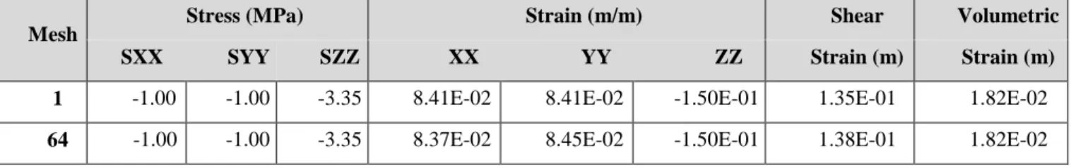
(16) Thèse de Faten Rafeh, Lille 1, 2015. Figure 1.23. Lithographic map of North Region, France – by BRGM. Figure 1.24. Geological section of the substratum at Lezennes, North France (M. Dubois, 2009). Figure 1.25. Transversal section of the substratum at a zone of study in Lille Metropolis (Dubois, 2010). Figure 1.26. Cathedral of Saint Maurice in Lille constructed using the chalk extracted from underground layers.. Figure 1.27. Behaviour of the chalk of Lezennes, North France at (a) low, and (b) high confining pressures (Bederiat, 1989 and Siwak, 1994).. Figure 1.28. Mechanical fissures and faults at the pillars. Figure 1.29. Variation of the Young modulus in terms of the degree of saturation.. Figure 1.30. Variation of the elastic limit in terms of the degree of saturation.. Figure 1.31. Variation of the resistance to uniaxial compression in terms of the degree of saturation.. Figure 1.32. Karstic effect in the cavity of cavagniac, Lille.. Figure 1.33. Typical Creep Curve. Figure 1.34. Creep triaxial tests performed on the chalk of Lezennes, North France under different confining pressures (σ3) (by Dahou, 1995). Figure 1.35. Creep triaxial tests performed on the chalk of Lezennes, North France at different deformation rates (έ1) (by Dahou, 1995). Figure 1.36. Surface damage at Boisselle, Lille - La Voix du Nord, 2015. Figure 1.37. Flow diagram highlighting the major topics of the thesis.. Figure 2.1. Flow Chart representing the numerical approach of the constitutive law with two embedded joint sets.. Figure 2.2. Geometry of the modelled chalk specimen. Figure 2.3. Sketch showing a vertical section of a zone of the chalk continuum with joints. (a) single joint set, (b) double joint sets, (c) symmetric joint sets. Figure 2.4. Axial Stress vs. Axial Strain. Figure 2.5. Deviatoric Stress vs. Volumetric Strain. Figure 2.6. Sketch showing the dip direction (jdd) and the dip angle (jdip).. Figure 2.7. Volumetric Strain and Axial Strain vs. Deviatoric Stress for different jdd and jdip.. Figure 2.8. Volumetric Strain and Axial Strain vs. Deviatoric Stress at different dip angles or θz.. Figure 2.9. Variation of ultimate resistance with the variation of the weak plane inclination θz.. xiv © 2015 Tous droits réservés.. doc.univ-lille1.fr.
(17) Thèse de Faten Rafeh, Lille 1, 2015. Figure 2.10. Evolution of deviatoric stress at different inclinations of weak plane θz.. Figure 2.11. Variation of the axial stress with the variation of the weak plane cohesion.. Figure 2.12. Variation of the axial stress with the variation of the weak plane friction.. Figure 2.13. Stress-strain graphs for triaxial test of chalk continuum with different constitutive models.. Figure 2.14. Comparison of the strength of the chalk examined by existing ubiquitous joint model and the proposed jointed model.. Figure 2.15. Stress-strain graphs for triaxial test of chalk continuum with proposed yield criterion at different joint set inclinations. Figure 2.16. Displacement distribution with joints inclined at (a) θz = 0° (vertical joint set) (b) θz = 90° (horizontal joint set) (c) θz = 120° (d) θz = 150°.. Figure 2.17. Variation of deviatoric stress with respect to joint set inclination at different joint friction angles.. Figure 2.18. Variation of the deviatoric stress with the inclination of the weak planes.. Figure 2.19. Variation of the volumetric strain with respect to the variation of inclination angle α of the symmetric weak planes.. Figure 2.20. Displacement distribution about z-axis (a and b) or y-axis (c and d) of models with single joint (a and c) or models with two symmetric joints (b and d).. Figure 3.1. (a) Underground quarry in Hellemes- North France (Lille Municipality, 2013), (b) Top section of the room and pillar quarry. Figure 3.2. (a) Section of the excavation model showing the mesh, (b) Section of the excavation model showing the boundary conditions.. Figure 3.3. Variation of FRF with respect to angle of weak plane α.. Figure 3.4. Zoom on the void zone of the cavity model: Horizontal stress displacement on a section of the cavity model. (a) vertical joints, (b) horizontal joints.. Figure 3.5. Comparison of FRF versus joint set inclination angle α in case of single joint set and double symmetric joint sets.. Figure 3.6. Deformation profile of the excavation model in different joint sets conditions. (a) single vertical joint set parallel to xz-plane, (b) single horizontal joint set parallel to xy-plane, (c) single non-vertical joint set inclined at 45°, (d) double symmetric non-vertical joint set inclined at 45°.. Figure 3.7. Contour of maximum shear strain in the excavation model. (a) Vertical joint sets, (b) Horizontal joint sets.. Figure 3.8. Displacement Contours of the excavation model in different joint sets conditions. (a) single non-vertical joint set inclined at 30°, (b) double symmetric non-vertical joint set inclined at 30°, (c) single non-vertical joint set inclined at 60°, (d) double symmetric non-vertical joint set inclined at 60°.. Figure 3.9. Settlement at the surface of the excavation model at different joint cases.. xv © 2015 Tous droits réservés.. doc.univ-lille1.fr.
(18) Thèse de Faten Rafeh, Lille 1, 2015. Figure 3.10. Deflection of the roof of the gallery of the excavation model at different joint cases.. Figure 3.11. Buckling of the pillar of the excavation model at different joint cases.. Figure 3.12. Plot of FRF against the settlement at the mid-span of the roof of the gallery.. Figure 4.1. Sketch of the (a) multi-pillar system, (b) cavity symmetric model with assigned boundary conditions.. Figure 4.1c. Sketch showing the joint inclination angle α in a zone of the jointed chalk continuum.. Figure 4.2. Evolution of the displacement (m) contours with time. Case of joint set inclined at α = 45° and γ = 10-1(1/t).. Figure 4.3. Displacements at 10 years after excavation. Joint set inclined at α = 0°, 30°, 45°, 60°, and 90°(from left to right).. Figure 4.4. (a) Shear and (b) volumetric strain distribution after 10 years from excavation for different joint set inclinations.. Figure 4.5. Evolution of the degradation factor D in the cavity model with joint set inclined at 45°.. Figure 4.6. Evolution of the hardening parameter Rm and the degradation factor D with time. Figure 4.7. Degradation evolution at different admissible degradation amounts. Figure 4.8. Degradation rate (average in massive) for different cases of (joint set inclined at 45°).. Figure 4.9. Evolution of (a) Rm, maximum and (b) average values, for different cases of .. Figure 4.10. Evolution of (a) D, maximum and (b) average values, for different cases of .. Figure 4.11. Evolution of degradation in the pillar considering the 5 different cases of :. Figure 4.12. Evolution of the coefficient of variation of D considering the 5 different cases of :. Figure 4.13. Evolution of (a) Rm(average) and (b) Rm of Pillar (average) with time, for different cases of joint inclination (α).. Figure 4.14. Evolution of (a) D(average) and (b) D of Pillar (average) with time, for different cases of joint inclination (α).. Figure 4.15. Degradation rate (average in massive) for different cases of (joint set inclined at 45°).. Figure 4.16. Evolution of the lateral stain at the pillar section applying both approaches.. Figure 4.17. Evolution at the pillar centre applying both approaches.. Figure 4.18a. Evolution of horizontal displacement at the pillar. Results corresponding to degradation approach.. xvi © 2015 Tous droits réservés.. doc.univ-lille1.fr.
(19) Thèse de Faten Rafeh, Lille 1, 2015. Figure 4.18b. Evolution of horizontal displacement at the pillar. Results corresponding to reduction approach.. Figure 4.19a. Evolution of vertical displacement at the roof. Results corresponding to degradation approach.. Figure 4.19b. Evolution of vertical displacement at the roof. Results corresponding to reduction approach.. Figure 4.20. Evolution of vertical and horizontal displacements at roof and pillar respectively.. Figure 4.21. The decrease of strength properties of the joints, (a) friction and (b) cohesion, imposed by the degradation and reduction approaches used in our analysis.. Figure 4.22. Evolution of horizontal, shear, and vertical stresses in the room-and-pillar cavity model. Case of study. Figure 4.23. Evolution of (a) shear and (b) volumetric strain at different periods (0.5 years, 10 years, and 100 years from left to right). Case of study: Joint set inclined at 45° from z-axis.. Figure 4.24. Evolution of axial stresses and strains at roof via both approaches: (a) degradation, and (b) reduction. Joint set inclined at 45°.. Figure 4.25. Evolution of axial stresses and strains at roof via both approaches: (a) degradation, and (b) reduction. Joint set inclined at 45°.. Figure 4.26. Evolution of lateral stress at roof via both approaches: (a) degradation, and (b) reduction. Joint set inclined at 45°.. Figure 4.27. Evolution of lateral strain at roof via both approaches: (a) degradation, and (b) reduction. Joint set inclined at 45°.. Figure 5.1. Room-and-pillar quarry in Lille.. Figure 5.2. Numerical results: Factor of safety with respect to W:H ratios for different L values.. Figure 5.3. Variation of simulated Fs with respect to L values at different W:H ratios.. Figure 5.4. Top and vertical sections of the room-and-pillar underground structures.. Figure 5.5. Variation of the simulated pillar strength as a function of pillar width.. Figure 5.6. Normalized values of Rp with respect to L.. Figure 5.7. Degraded pillar in the cavity of Don Bosco in Lille on October 2011.. Figure 5.8. Logigram of the approach proposed for the formulation of Fs (emp).. Figure 5.9. Results of the first regression analysis performed between simulated Rp values and W:H ratios.. Figure 5.10a. Correlation between numerical and empirical results of Rp calculations.. Figure 5.10b. Correlation between numerical and empirical results of Fs calculations.. Figure 5.11. Abacus for the estimation of critical width of safety pillars with given height. xvii © 2015 Tous droits réservés.. doc.univ-lille1.fr.
(20) Thèse de Faten Rafeh, Lille 1, 2015. H and spacing L. Figure 5.12. Pillar with reduced section from the cavity of Cavaignac, Lille.. Figure 5.13. Abacus to determine the admissible scaling of the pillar section for any W, H, and L in the studied range.. Figure 5.14. Fracture at 45° in the pillar of the Cavaignac cavity at Lille in September 2011.. Figure 5.15. Simulated safety factors with respect to all possible permutations of dimensions and joint inclinations. Figure 5.16. Linear relation between empirical and numerical Fs of cases without and with joints, respectively.. xviii © 2015 Tous droits réservés.. doc.univ-lille1.fr.
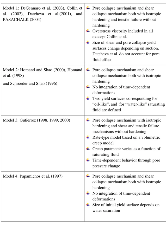
(21) Thèse de Faten Rafeh, Lille 1, 2015. LIST OF TABLES. Table 1.1. Summary of Elasto(visco)plastic Constitutive Models for Chalk. Table 2.1. Mechanical properties of chalk including matrix and joints. Table 2.2. Stresses and strains values. Table 4.1. Synthesis table of the works accounting for time-dependent behaviour. Some of time independent stability analyses are highlighted. Table 4.2. Values of mechanical soil properties. Table 4.3. Comparison between the degradation and the c/phi reduction approaches. Table 5.1. Summary of geometric characteristics used in the numerical study. Table 5.2. Summary of mechanical properties used in the numerical study.. xix © 2015 Tous droits réservés.. doc.univ-lille1.fr.
(22) Thèse de Faten Rafeh, Lille 1, 2015. xx © 2015 Tous droits réservés.. doc.univ-lille1.fr.
(23) Thèse de Faten Rafeh, Lille 1, 2015. SYMBOLS. Fs. Factor of Safety. Rf. Reduction Factor. E. cj. Young Modulus (Pa) Poisson Ratio Matrix Cohesion (Pa) Matrix Friction Angle () Dilation Angle () Joint Cohesion (Pa). j. Joint Friction Angle (). j. Joint Dilation Angle (). K0. Coofficient of Earth Pressure at Rest. fj. Joint Failure Function. f jdeg. Relative to Degradation Approach. f jred. Relative to Reduction Approach. gj. Joint Potential Function. . Full Stress Tensor Normal Vector to Joint Plane Normal Stress Tensor. c. . n. n . Tangential Stress Tensor. xxi © 2015 Tous droits réservés.. doc.univ-lille1.fr.
(24) Thèse de Faten Rafeh, Lille 1, 2015. Rm. Plastic Hardening Function. B. p. Constant affecting the Hardening Rate Plastic Shear Strain. eijp. Deviatoric Plastic Strain. deijp. Deviatoric Plastic Strain Increment. ijp. Total Plastic Deformation. ije. Total Elastic Deformation. ijp. Kronecker Tensor. C. Stiffness Tensor Plastic Multiplier Degradation Factor. D D* . Degradation Function Material Constant Constant to limit Degradation. xxii © 2015 Tous droits réservés.. doc.univ-lille1.fr.
(25) Thèse de Faten Rafeh, Lille 1, 2015. GENERAL INTRODUCTION. Underground cavities constitute a serious geological hazard due to the consequential collapses developed on the overlaying terrain. In urban areas, generally the sudden collapse causes damages to properties, infrastructure, and even lives. Hence, it is a real challenge for land use planners and engineers to provide adequate safeguards to reduce the consequences of this hazardous phenomenon and prevent the substantial risks. Yet, such provisions have to be based on a broad understanding of the nature of induced instabilities and the global mechanical behaviour of the underground cavities. North France is one of the regions threatened by such risks due to the high presence of anthropogenic underground cavities. The exploitation of these cavities was accompanied with the economic and demographic development of this region that had to face in the nineteenth century the strong population growth by building large urbanized sets. The excessive demand of construction material in that period urged the extraction of huge amounts of rock and particularly chalk blocks. According to the City of Lille in North France (Ville de Lille 2012 and 2013), more than 4,500,000 cubic meters of voids have been identified in the underground layers of Lille Metropolis in a survey done in 2009. Large surfaces in this region are now under-mined by underground cavities which constitute a source of serious insecurity problems for the population, constructions and infrastructure, as well as the urban planning and impending development projects For this reason, the City of Lille in North France and particularly the Service of Urban and Health Risks has launched a project endorsed under the Plan for Prevention of Risks (PPR) and concerned particularly in the study of the phenomenon of underground cavities. This project is known as the ‘Plan National Cavité’, where it includes several axes which come across. One is dedicated for the naturalistic surveys and observations at these cavities. 1|P age © 2015 Tous droits réservés.. doc.univ-lille1.fr.
(26) Thèse de Faten Rafeh, Lille 1, 2015. performed based on regular geological investigations. This provides measures of displacements occurring at the cavities, inspection of new features developing such as induced fractures, and continuous alert against any sudden disorders. A second axe is devoted to the experimental work and testing done on chalk samples taken from the cavities. This is needed to illustrate the mechanical behaviour of the chalk under real conditions. Another axe is concerned in the numerical analysis of the behaviour of these cavities. Numerical tools could be efficient in such a study since it is possible to investigate different existing cases of cavities under varying external and internal conditions and at the same time consider an envelope of these cases and conditions too. Besides, it is possible to model the foreseeable deformation profiles with the associated failure mechanisms and investigate the stability state of the cavity. In this research, we deal with the third axe taking into account the outcomes obtained on the other two levels. Our main intention throughout this work is to provide by means of numerical analysis a complementary understanding of the deformational behaviour and the stability state of these cavities under different circumstances. In this thesis, a numerical study is conducted to assess the stability of shallow underground cavities identified in the chalk layers of Lille and its region in North France. From a safety point of view, these cavities are not only required to prevent ultimate collapse, but also to avoid deformations due to encountered instabilities and thus satisfy limits of a displacement-based criterion. Major topics of this work are illustrated within five chapters: o Chapter One An overview about the phenomenon of underground cavities in France and particularly in North France is advocated in the first chapter. An idea about the reasons behind excavating huge areas, the common methods of exploitation, and the encountered risks is provided. The particularity of the cavities in the zone of study is addressed showing the main highlights of this work. Cavities of Lille and its region in North France were excavated in the chalk layers at shallow depths and most frequently using the method of rooms-and-pillars. Frequent failure mechanisms in this type of exploitations are discussed. This is associated with a review on the research works done addressing this problematic in terms of numerical modelling basically. Afterwards, a description of the behaviour of chalk and the relevant yield mechanisms is done. A state of the art concerning the stress-strain behaviour including. 2|P age © 2015 Tous droits réservés.. doc.univ-lille1.fr.
(27) Thèse de Faten Rafeh, Lille 1, 2015. the effects of material structure like anisotropy induced by the presence of joints, the waterdependent behaviour in accordance with the featured physical aspects, and the time dependent behaviour in the presence of various aggravating factors, is performed. An outline of the provisions and the novelty of this thesis are stated at the end of this chapter. o Chapter Two In the study of underground instabilities originating from the quarries excavated in the jointed chalk bed, it is necessary to understand the behaviour of the jointed continuum. Discontinuities such as stratigraphic joints and induced fractures inherently affect the material strength and deformational behaviour especially at shallow depths where mean stresses are low and failure is rather driven by shear at the discontinuities. In chapter two, an equivalent continuum constitutive model accounting for the critical effect of anisotropy induced by the presence of joints is proposed. In this model, two joint sets are defined implicitly in the chalk continuum and an oriented yield criterion is developed to simulate the stresses induced on these joints. Three yield envelopes are defined separately for the chalk matrix (representing the intact part of the continuum) and the two joint sets. Failure is tested and whenever it is detected, relevant plastic corrections are applied. Based on the theory of multi-mechanisms for plastic strain (Koiter 1953 and 1960), updated stresses are recuperated all over the chalk continuum. Triaxial tests are simulated on models with single and double joint sets. Comparisons with results based on existing models are illustrated to verify the applicability of the proposed model. Stress-strain responses and failure modes are investigated to describe the strength and deformational behaviour of the anisotropic chalk. o Chapter Three In this chapter, we use the joint model developed in chapter two to integrate the joint effect in the mechanical behaviour of the underground cavities excavated in jointed chalk layers. The major intention is to study the impact of joints, whatever its nature is whether stratified joints or induced fractures, on the strain and failure mechanisms as well as on the stability state of the cavities. A three dimensional numerical modelling of the excavation operation of these cavities is developed. Both geometric characteristics of the room-and-pillar quarries and the mechanical properties of the soil and chalk layers are inspired from site investigations and experimental tests done in the zone of study. The oriented criterion developed is assigned for. 3|P age © 2015 Tous droits réservés.. doc.univ-lille1.fr.
(28) Thèse de Faten Rafeh, Lille 1, 2015. the behaviour of the joints as mentioned before. Strain profiles are simulated and the effect of joints is analysed considering different properties and orientations too. In order to assess the effect of joints on the failure mechanisms and the stability state of these cavities, a stability criterion is implemented and assigned to the joints. Since in shallow excavations dominating failure is often realized by shear, the criterion used was based on the conventional shear strength reduction technique. The safety factor is calculated taking into account the presence of joints. Numerical analysis is carried out to provide a better understanding of the critical effect of joints or discontinuities on the global behaviour and stability of the cavities. In other words, it illustrates the influence of induced anisotropy on the stability and failure mechanisms of the underground galleries excavated in jointed chalk layers of North France and its region. o Chapter Four In the investigation of ancient unexploited cavities, it is of high importance to account for the effect of time on the resistance of the cavity and in the presence of various aggravating factors. This chapter addresses the time-dependent study conducted to analyse the long term stability of the underground cavities. Usually, the type of time-dependent deformation known as creep deformation is entirely related to the viscous effects of the material and is analysed using models of viscoelasticity and viscoplasticity (Perzyna, 1966, and Cristescu, 2009). In this work, a methodology based on the law of hardening and micro-structural evolution inspired by Shao et al. (2003) is used to generate both instantaneous and time dependent irreversible deformations of the degraded chalk. This is achieved in the presence of the joints defined previously in the continuum of the model. Unlike the conventional reduction methods that are used to simulate stability, the developed time-dependent-degradation approach implements a non-homogeneous kinetic reduction of the resistive shear properties of chalk producing a non-uniform evolution of shear plastic strains in the room-and-pillar model. Numerical analysis of the time dependent behaviour that accounts for the associated physical aspects is performed. The influence of varying joint orientations is also considered. A comparison with results obtained using the conventional shear strength reduction method is also done. This provides a physical interpretation and a better understanding of the time dependent behaviour and the progressive failure associated in these quarries after a long time from excavation.. 4|P age © 2015 Tous droits réservés.. doc.univ-lille1.fr.
(29) Thèse de Faten Rafeh, Lille 1, 2015. o Chapter Five In chapter five, we intend to run a parametric study that accounts for the range of different geometries of the room-and-pillar quarries, including different width to height ratios of pillars (W:H) and spans of void rooms/galleries (L), aiming to achieve two purposes. The first one is illustrating the effect of confining pressure which is directly related to the dimensions of the supporting pillars and void rooms in the quarry on the nature of the rupture mechanisms, i.e, whether brittle or ductile. The next purpose is achieved by complementing the parametric study-based-numerical results with a third order regression analysis. Thereafter, extrapolated formulae for the preliminary estimation of the resistance of the pillar and the safety of the room-and-pillar quarry are developed. The same study is performed in the presence of one joint set at three different orientations and consequently three new corresponding formulae are proposed in the same context. In addition, an abacus is generated for the direct estimation of the critical width of the pillars and another one to determine the maximum permissible scaling of pillars with different dimensions such that they stay in the safety zone. This might provide a feasible and helpful tool for geo-engineers involved in this project with the City of Lille since it is now possible, being only given its dimensions and the orientation of the detected discontinuities, to assess the stability of the underground cavity.. 5|P age © 2015 Tous droits réservés.. doc.univ-lille1.fr.
(30) Thèse de Faten Rafeh, Lille 1, 2015. 6|P age © 2015 Tous droits réservés.. doc.univ-lille1.fr.
(31) Thèse de Faten Rafeh, Lille 1, 2015. CHAPTER ONE UNDERGROUND CAVITIES: A DESCRIPTIVE OVERVIEW – STATE OF THE ART. 1.1 Introduction The important concentration of unexploited underground cavities in close proximity to urbanized areas poses problems in terms of security of both people and constructions at one hand, and induces a constraint against planning and urban development at the other hand. Hence, it is of major interest to conduct a study about this phenomenon aiming to understand the behaviour of the underground cavities, estimate their stability state and provide insights about the shape and intensity of expected damage, and last but not least give some provisions on how to limit the substantial risks encountered due to consequential instabilities. From this perspective, this thesis comes to suggest some sorts of a better understanding of this issue after raising a couple of questions such as: Why were these cavities formed? Where in France are they massively located? How were they excavated? What are the risks on both: land and constructions, and people? What are the regulations proposed by authorities of concerned cities such as the City of Lille in North France? What is the particularity of the cavities of North France? What achievements have been made in this domain, whether in terms of numerical study, empirical analysis, or constitutive modelling? What are the novel propositions in this thesis concerning the problematic of underground cavities or in other words where do the innovation and originality of this work lay?. 7|P age © 2015 Tous droits réservés.. doc.univ-lille1.fr.
(32) Thèse de Faten Rafeh, Lille 1, 2015. 1.2 Why were underground cavities formed and where are they concentrated throughout the French territory? Since ancient times and until now, civil engineers have found in the extraction of intact rock masses from underground layers a nourishing source to support them permanently with construction materials needed in their building works for both structural and infrastructural development. Consequently, this type of exploitations has ended up in the formation of large areas of anthropogenic underground cavities known as quarries. Other motives stood behind excavations of underground cavities such as military ones where combatants used cavities as shelters and underground passages among villages. Some were excavated for agricultural uses after finding out that the environment inside the cavities is convenient for certain cultivations such as mushrooms cultivation for example. Throughout the French territory, underground cavities cover tens of thousands hectares of the area. It is more frequent in layers of chalk, limestone, gypsum and marble materials that were extracted to be used in construction works. Figure 1.1 shows the distribution of different types of underground cavities in France including both natural (in yellow) and anthropogenic cavities excavated in different ground layers like chalk (in green) and others. Most of these quarries are very ancient by which some belong to the seventh century (suburbs of Lille, North France), others to the eleventh, fourteenth and fifteenth century (Caen, Normandy and Paris, Picardy). The development of the operation of underground openings, however, reached its peak between the seventeenth and nineteenth century (Mikolajczak 1996, Ineris, 2007, 2012, Courbot et al. 2009, Ville de Lille 2012 and 2013). This was accompanied by the economic and demographic development of many regions and cities that have faced in the nineteenth century strong growth in population which in turn required building new large urbanized sets. For many centuries, such operations were carried out without authorization or any type of supervision. These resulted in problems of instability at or beneath the location of these quarries which started to gain concern after a series of serious accidents that occurred in late eighteenth century in Paris region (see section 1.4.2). The concentration of such incidents in different regions of France is shown in Figure 1.2.. 8|P age © 2015 Tous droits réservés.. doc.univ-lille1.fr.
(33) Thèse de Faten Rafeh, Lille 1, 2015. Figure 1.1. Distribution of underground cavities in France, 1994 - by BRGM. Very strong Strong Medium Weak Null to very weak. Figure 1.2. Hazard associated with underground cavities in France – by BRGM. 9|P age © 2015 Tous droits réservés.. doc.univ-lille1.fr.
(34) Thèse de Faten Rafeh, Lille 1, 2015. 1.3 How. were. the. underground. cavities. excavated:. Exploitation methods? The typology of underground quarries is based on the diversity of the exploitation methods used. The most frequent exploitation methods used in the excavation of underground cavities in France are described below (Ineris, 2007):. 1.3.1 Room-and-pillar exploitations This method is the oldest and the most commonly used where it showed up after the nineteenth century. It is characterized by a regular, almost orthogonal distribution of pillars with different sections to ensure sufficient stability. Usually, it consists of a vertical well of 8 to 30 meters depth linked to a network of galleries with pillars supporting the overburden. The constituent materials were extracted sorted through the wells, and the waste was discarded forming a thick fill layer on the floor of the galleries. At the end of the operation the wells were backfilled from the surface to keep plane topography. This method has been largely used in the North France. In Lille Metropolis, 80% of the quarries were excavated by the 'room-and-pillar' method. For this reason, this study focuses on the study of this type cavities (Figure 1.3 and Figure 1.4).. Figure 1.3. Rooms-and-pillars cavities - Document by City of Lille. 10 | P a g e © 2015 Tous droits réservés.. doc.univ-lille1.fr.
(35) Thèse de Faten Rafeh, Lille 1, 2015. Figure 1.4. Rooms-and-pillars cavities in Hellemes, North France. 1.3.2 Exploitations by holts-and-bottles This method has started by the end of the nineteenth century and is often regular in terms of geometry and organization. In this type of underground excavations, the wells are of regular reparation and made in the shape of a bottle attached to a small gallery. The waste is abandoned at the bottom forming hills of embankment. At the end of the operation, a closure was done at the head by blocks of chalk corbelled to maintain the stability (Figure 1.5 and Figure 1.6).. Figure 1.5. Exploitations by holts-and-bottles – by City of Lille. 11 | P a g e © 2015 Tous droits réservés.. doc.univ-lille1.fr.
(36) Thèse de Faten Rafeh, Lille 1, 2015. Figure 1.6. Holts-and-bottles cavity at Lezennes, North France. 1.3.3 Mixed type exploitations This is a combination between the rooms and pillars method and the method of holts and bottles within the same quarry. Here the pillars will be more regular than in the chambers and pillars method.. Figure 1.7. Type of underground cavities in North France – BRGM. 12 | P a g e © 2015 Tous droits réservés.. doc.univ-lille1.fr.
(37) Thèse de Faten Rafeh, Lille 1, 2015. 1.4 Common Risks 1.4.1 Risks at the surface The main risks arising from the presence of underground cavities correspond to the surface manifestation of disorders whose effects differ depending on the associated failure modes and the nature of the land forming the cover. Common surface accidents are described below (City of Lille, 2012).. Figure 1.8. Accident close to a house in Normandy, France, 2001 - Document by LCPC. 1.4.1.1. The generalized collapse. This type of collapse is reflected by a violent and spontaneous lowering of the surface sometimes covering several hectares and reaching several meters in depth while the ground above the cavity collapses suddenly (Figure 1.9). Failure mechanisms that trigger the spontaneous collapse are preceded by different and somehow complex instability processes like fractures in the pillars, roof collapse, punching of the walls, shear boards spacers or inconvenient superposition of pillars among different exploited levels, hydraulic loading of the roof, deviation of the stress field in case of inclined overburdens, human actions, etc. This type of phenomenon can cause huge damage to buildings and serious substantial losses like victims because of the remarkable speed and magnitude of this phenomenon (Figure 1.10).. 13 | P a g e © 2015 Tous droits réservés.. doc.univ-lille1.fr.
(38) Thèse de Faten Rafeh, Lille 1, 2015. Figure 1.9. Sketch of the generalized collapse – Document by INERIS. Figure 1.10. Case of generalized collapse in Lille, North France. 1.4.1.2. The collapse by localized rupture at pillars. This localized rupture occurs when one or more pillars are no more able to support the weight of the overburden and other existing loads. This might happen due to the small effective section and may thus lead to failure in this pillar. Consequently, the applied loads are redistributed among the adjacent supporting pillars which might become overstressed due to the additional loads. In this case, other pillars are subjected to fail gradually ending up with a total collapse of the whole gallery (Figure 1.11).. 14 | P a g e © 2015 Tous droits réservés.. doc.univ-lille1.fr.
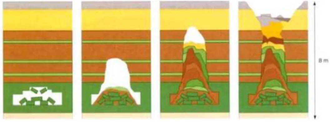
(39) Thèse de Faten Rafeh, Lille 1, 2015. Figure 1.11. Scenario of the pillars rupture – by SEISM, 2008. 1.4.1.3. The collapse localized by roof rupture/ sinkholes. In general, sinkholes (fontis) correspond to a sudden but localized collapse manifesting itself in the form of a funnel or crater from the bottom towards the top. It is most often caused by the progressive failure that extends gradually to the roof of a cavity, and leads abruptly to creating a circular funnel with a diameter that can vary from a few meters to several tens of meters on the surface. The sinkholes occur most often in the form of a cone whose slope angle is related to the slope angle of the natural land. For a 45° angle, the radius surface is equal to the depth of the cavity (Figure 1.12 and Figure 1.13).. Figure 1.12. Sketch of the development of a sinkhole - (Ineris, 2007). 15 | P a g e © 2015 Tous droits réservés.. doc.univ-lille1.fr.
(40) Thèse de Faten Rafeh, Lille 1, 2015. This type of instability takes place frequently since it can occur over any empty mid-average extension (abandoned galleries, wells, karst). Sinkholes can cause significant damage to close structures and this phenomenon is usually associated with a high risk of physical victims because of the speed and dimensions of the phenomenon.. Figure 1.13. Sketch showing the sinkhole formation by upward progression - BRGM. 1.4.1.4. Subsidence or sagging. Subsidence or sagging is a flexible deformation that does not really leave remarkable damage. It results in a topographic depression generally bowl-shaped with a flat bottom and bent edges (Figure 1.14). This type of disorder sometimes develops over several hectares at the place of large quarries or mines. Subsidence can cause disturbances in the adjacent buildings but without really causing physical victims due to the fact that this phenomenon occurs slowly (Figure 1.15).. Figure .1.14. Descriptive sketch of sagging – Document by INERIS. 16 | P a g e © 2015 Tous droits réservés.. doc.univ-lille1.fr.
(41) Thèse de Faten Rafeh, Lille 1, 2015. Figure 1.15. Generalized subsidence on surface over a chalk quarry at Indre et Loire, France Document by INERIS. 1.4.1.5. Other types: Suffosions and Stripping. Two other types of surface accidents known as stripping and suffosions are directly related to the water circulation in case of rainfall in the area of the underground cavities. Stripping corresponds to the gravity drive, usually caused by massive water circulation, and material filling a cavity. This type of phenomenon can lead to the sudden onset of an empty surface, usually not more than a few square meters. This is the risky phenomenon that affects most natural networks developed in the limestone massifs. During heavy rainfall, the water circulation in depth can enforce the material which initially filled the large cracks, to strip and break and get to the surface leaving a gaping hole in the rock. Suffosion is an internal erosion phenomenon which affects mainly sand and silt. It consists of a particle entrainment in the soil mass due to rapid pore water circulations. Later, a part of these fine particles is released, so, real hoses can develop. When the size of these gaps becomes excessive, brutal sinkholes might occur in local places causing disorders at the surface.. 1.4.2 Risks on people Underground cavities are known for the threatening hazards not only for the damage they append to the environment; land and constructions; but also because of the direct risk they. 17 | P a g e © 2015 Tous droits réservés.. doc.univ-lille1.fr.
(42) Thèse de Faten Rafeh, Lille 1, 2015. induce on the lives of the people living in the surrounding. They are considered to have both socio-economic and human consequences. Based on the Ineris reports, some incidents were recognized (Ineris, 2007): . The majority of human accidents are caused by degradation of abandoned underground quarries that were exploited by the room-and-pillar method. The death toll recorded between 1778 and 1998, gave 62 dead and 73 wounded;. . The highest loss was observed in the Paris region, probably due to the extreme density of exploitations in urban areas;. . Most events of localized collapse listed are basically subsidence (more than 90% of cases). Fortunately, they cause the most often small number of victims (1 or 2 per accident);. . The widespread (generalized) collapse of one to several hectares are rare (1 only for the period 1950-1998), but very deadly.. In addition, some risks are related to the access to the abandoned underground cavities where many visitors who came to explore these cavities without any previous planning got lost. The risk is not only related to probable unawareness, but also to the inconvenient atmosphere in these cavities due to the loss of oxygen, presence of allergic organic material, release of dangerous gas from contaminants, pollution of the water table, and others.. 1.5 What are the regulations taken by concerned authorities towards this problematic? Today, studying the deformational behaviour and the failure mechanisms associated in underground quarries, predicting and preventing the consequential risks of generated aleas, as well as developing adequate safeguards for both people and properties, have become major objectives of the responsible authorities of the cities concerned by the hazardous phenomena generating from the underground cavities. In France, a high concentration of these cavities and the corresponding aleas was identified in the Northern region (Figure 1.1 and Figure 1.2). To date, several damages, whether minor or substantial, have been recorded in urbanized areas in this region whereas some zones are classified under permanent risk of abrupt. 18 | P a g e © 2015 Tous droits réservés.. doc.univ-lille1.fr.
(43) Thèse de Faten Rafeh, Lille 1, 2015. collapses due to the instabilities originating from underlain shallow cavities and their close proximity to urbanized areas. Figure 1.16 for example shows the access of a cavity in Hellemes, North France which is located in the garden of a nursery school where the cavity is few meters under this school and it extends over hectares by width to underlain streets and residences in the area. Figure 1.17 is taken during a site visit to this cavity in June 2012.. Figure 1.16. Access to the underground quarry in Hellemes, North France.. Figure 1.17.Undeground Quarry in Hellemes, North France.. As reported by the City of Lille, 15% of the population is nowadays exposed to this risk. More than 364 incidents of collapses, subsidence, and landslides have been recorded to date due to the presence of underground quarries (Ineris, 2007, 2012, Courbot et al. 2009, Ville de. 19 | P a g e © 2015 Tous droits réservés.. doc.univ-lille1.fr.
(44) Thèse de Faten Rafeh, Lille 1, 2015. Lille 2012 and 2013). An example of a recent incident that shows the volume of collapse in a district in Lille is provided (Figure 1.18). Being aware to the circumstances of this hazardous phenomenon, the Service of Urban and Health Risks of the City of Lille has launched a ‘Plan for the Prevention of Risks’ (PPR) including urgent regulations and prerequisites to avoid anticipated risks and control the encountered damage in threatened regions.. Figure 1.18. General view of the collapse above the Don Bosco cavity in Lille recorded in February 2012 (by City of Lille). This plan is associated to the project enrolled on risks of underground quarries in collaboration with several parities by which different aspects based on naturalistic, instrumental, and numerical approaches are advocated. A combination of these latter leads to identify the zones of threatened areas, evaluate the volume and intensity of risk, understand the mechanical behaviour of the underground cavities, model the modes of deformation and failure, and last but not least establish stability state predictive tools and suggest appropriate protective measures.. 1.6 Underground cavities of North France: Zones of concentration The area of the underground quarries in Lille and its region in North France is estimated by120 hectares and risks cover about 300 hectares of the above surface (mainly in Lille Sud,. 20 | P a g e © 2015 Tous droits réservés.. doc.univ-lille1.fr.
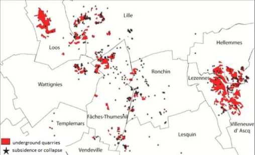
(45) Thèse de Faten Rafeh, Lille 1, 2015. Moulins, and Faubourg de Bethune) (Mikolajczak, 1996, Ineris, 2007, Courbot et al. 2009, Ville de Lille 2012 and 2013). Maps provided on the website related to this issue: cavites.fr (Figure 1.19) and others from the City of Lille (Figure1.20 and Figure 1.21) show the repartition of quarries and zones of risk in North France and particularly in urbanized regions of the sectors of Lille and Hellemes in North France (Ville de Lille).. Figure 1.19. Types of underground cavities in North France - www.cavites.fr. Besides, a map showing the location of underground quarries in Lille Metropolis with the density of identified collapse incidents is provided the City of Lille (Ville de Lille 2012 and 2013).. Figure 1.20. Distribution of identified cavities in Lille - by City of Lille. 21 | P a g e © 2015 Tous droits réservés.. doc.univ-lille1.fr.
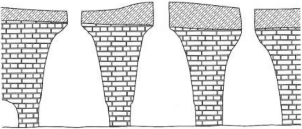
(46) Thèse de Faten Rafeh, Lille 1, 2015. Figure 1.21. Repartition of Identified Cavities in Hellemmes - by City of Lille. Figure 1.22. Repartition of underground quarries of Lille Metropolis and identified incidents until April 2010 (Document by City of Lille). 1.7 Common failure mechanisms in room-and-pillar quarries The mechanisms of rupture furthermore depend on the characteristics of the exploitation methods and the environment. Eighty percent of the quarries in North France were excavated by the method of rooms-and-pillars. Usually several failure mechanisms might be associated. 22 | P a g e © 2015 Tous droits réservés.. doc.univ-lille1.fr.
(47) Thèse de Faten Rafeh, Lille 1, 2015. with this type of exploitation where instabilities can be often localized at either the pillars or the roof. A description of the frequent failure mechanisms based on a review by Watelet (1996) is provided to give a better understanding of the mechanical behaviour of these quarries.. 1.7.1 Rupture of the Pillars/ Supports 1.7.1.1. Localized rupture of pillars. The localized ruptures are produced by the crushing of the pillars. Discontinuities or sometimes the heterogeneity existing in the pillars weaken them and make them incapable of supporting the exposed weight. Accordingly, this type of rupture leads to the damage of the roof and the appearance of the phenomena of widespread collapse or localized collapse as discussed before.. 1.7.1.2. Crushing by uniaxial compression. The section of the pillar carrying the stress applied on the surface by the weight of the covering layer, originally is of an identified resistance. When this applied pressure exceeds the resistance of the pillar, this latter will gradually cross the elastic limit and tend to collapse. In this case, the rupture of one pillar will simultaneously exhibit an additional stress on the neighbouring pillars and encourage their rupture as well. This mechanism develops rapidly. The principle stages of this damage is often materialized by the visual indices of degradation, cracking, detaching , falls of the facing, falls of the blocks, etc.. 1.7.1.3. Buckling of pillars after rupture of connecting/stabilizing bridges. This rupture mechanism appears due to the buckling of the pillars of almost high slenderness. Such a mechanism often takes place in the multilevel cavities where, initially the middle limestone connecting the bridge collapses, and hence pillars collapse after buckling due to the abruptly increased slenderness.. 23 | P a g e © 2015 Tous droits réservés.. doc.univ-lille1.fr.
Figure


+7


Documents relatifs