O
pen
A
rchive
T
oulouse
A
rchive
O
uverte (
OATAO
)
OATAO is an open access repository that collects the work of Toulouse researchers and
makes it freely available over the web where possible.
This is an author-deposited version published in: http://oatao.univ-toulouse.fr/
Eprints ID:
3954
To link to this article:
DOI: 10.1149/1.3298439
URL:
http://dx.doi.org/10.1149/1.3298439
To cite this version: Rieu, M. and Sayers, R. and Laguna-Bercero, M. A.
and Skinner, S. J. and Lenormand, Pascal and Ansart, Florence ( 2010)
Investigation of Graded La2NiO4+ Cathodes to Improve SOFC
Electrochemical Performance. Journal of The Electrochemical Society
(JES), vol.
157 (n° 4). B477-B480. ISSN 0013-4651
Any correspondence concerning this service should be sent to the repository
administrator:
[email protected]
Investigation of Graded La
2NiO
4+␦Cathodes to Improve SOFC
Electrochemical Performance
M. Rieu,aR. Sayers,bM. A. Laguna-Bercero,bS. J. Skinner,b,
*
P. Lenormand,a,z and F. Ansartaa
Institut Carnot Centre Interuniversitaire de Recherche et d’Ingénierie des Matériaux, Université Paul Sabatier, 31062 Toulouse Cedex 9, France
b
Department of Materials, Imperial College of Science, Technology and Medicine, London SW7 2BP, United Kingdom
Mixed ionic and electronic conducting共MIEC兲 oxides are promising materials for use as cathodes in solid oxide fuel cells 共SOFCs兲 due to their enhanced electrocatalytic activity compared with electronic conducting oxides. In this paper, the MIEC oxide La2NiO4+␦was prepared by the sol–gel route. Graded cathodes were deposited onto yttria-stabilized zirconia共YSZ兲 pellets by
dip-coating, and electrochemical impedance spectroscopy studies were performed to characterize the symmetrical cell perfor-mance. By adapting the slurries, cathode layers with different porosities and thicknesses were obtained. A ceria gadolinium oxide 共CGO兲 barrier layer was introduced, avoiding insulating La2Zr2O7phase formation and thus reducing resistance polarization of the
cathode. A systematic correlation between microstructure, composition, and electrochemical performance of these cathodes has been performed. An improvement of the electrochemical performance has been demonstrated, and a reduction in the area specific resistance共ASR兲 by a factor of 4.5 has been achieved with a compact interlayer of La2NiO4+␦between the dense electrolyte and
the porous La2NiO4+␦cathode layer. The lowest observed ASR of 0.11 ⍀ cm2at 800°C was obtained from a symmetrical cell
composed of a YSZ electrolyte, a CGO interlayer, an intermediate compact La2NiO4+␦layer, a porous La2NiO4+␦electrode layer,
and a current collection layer of platinum paste.
One of the most important goals in solid oxide fuel cell共SOFC兲 research is the reduction in the working temperature to about 700–800°C for future applications. However, at such intermediate temperatures, one of the main limiting factors is the high polariza-tion resistance of standard cathode materials, such as the conven-tional perovskite oxides based on La1−xSrxMnO3−␦共LSM兲, which
limits SOFC power densities.1,2Consequently, for some years, much attention has been focused on improving the cathodic performance by using both mixed ionic and electronic conducting materials, such as La1−xSrxCo1−yFeyO3−␦共LSCF兲,3,4and by improving the
micro-structural design at the cathode/electrolyte interface. Recent studies5-7 on mixed conductors indicated that the Ruddlesden– Popper phases with the K2NiF4-type structure have promising
prop-erties at intermediate operating temperatures due to their high ionic conductivity and high electrocatalytic activity,8-10which were corre-lated with additional oxygen on the interstitial site and the presence of cations with different oxidation states. Skinner and Kilner9 showed that the oxygen tracer diffusion coefficient of lanthanum nickelate共La2NiO4+␦兲 is greater than that of LSM and LSCF,
sug-gesting that the ionic conductivity of this oxygen excess material is superior.
Numerous authors have investigated the electrochemical perfor-mance of La2NiO4+␦ on yttria-stabilized zirconia 共YSZ兲
electrolytes.8,11,12 These initial studies have shown promising re-sults, and Laberty et al.11observed that significant improvements in the area specific resistance共ASR兲 values can be achieved with the composites of La2NiO4+␦and Ce1−xSmxO2−␦, which may be due to
better contacts. This study focuses on the preparation and electro-chemical characterization of a design of lanthanum nickelate graded cathodes for SOFC systems. In this work, we investigated a cathode structure composed of a thin Ce1−xGdxO2−␦共CGO兲 interlayer
depos-ited onto YSZ pellets, with an intermediate compact layer of La2NiO4+␦and a thicker porous layer of La2NiO4+␦.
The aim of using a layered microstructure design is to increase the number of contact points at the electrode/electrolyte boundary by introducing a thin intermediate layer of compact lanthanum
nick-elate between the electrode and electrolyte. A porous cathode layer deposited on top of this intermediate layer ensures adequate cata-lytically active sites for the oxygen reduction reaction to occur. This configuration allows an enlargement of the electrochemically active surface area at the cathode/electrolyte interface. In addition, en-hancement of the electrode current collection is investigated by the addition of a continuous platinum layer on top of the La2NiO4+␦
electrode.
To achieve a layered electrode structure, sol–gel processing and dip-coating deposition have the advantage of being easy methods to control both the microstructure and the composition of the electrode materials. The composition of the graded cathodes of lanthanum nickelate and the electrochemical performance of these symmetrical cells are reported here. The ASR values and Nyquist diagrams are discussed, and the microstructure of the electrode layers is corre-lated with performance.
Experimental
Preparation of symmetrical cells.— In this work, graded La2NiO4+␦ cells were prepared and deposited onto 0.5 mm thick
YSZ electrolyte substrates of 12 mm diameter by dip-coating. Dense YSZ substrates were prepared by spark plasma sintering of sol–gel prepared YSZ powders. Various configurations of the symmetrical cells were constructed, composed of an 80 nm layer of CGO, an intermediate layer of 2 m thick compact La2NiO4+␦, and an
8–15 m thick layer of porous La2NiO4+␦. Each YSZ support was
dipped either in a polymeric sol precursor of CGO or into slurries of La2NiO4+␦. The withdrawal speed was 5 cm min−1 for all
dip-coatings. The electrode layers for the symmetrical cell arrangements are given in TableI.
The CGO interlayer was prepared by a polymeric sol via a pro-cess similar to the Pechini13method. Solutions of the metal nitrates, Ce共NO3兲3·6H2O and Gd共NO3兲2·6H2O, were dissolved in deionized
water in stoichiometric proportions to obtain Ce0.8Gd0.2O2−␦as an
oxide compound. In parallel, a polymeric solution was prepared with acetylacetone 共acac兲 and hexamethylenetetraamine 共HMTA兲 dissolved in acetic acid. Both solutions were mixed and heated at 80°C to induce the formation of a polymeric chain by a condensa-tion reaccondensa-tion between acac and HMTA in acetic acid. The role of both HMTA and acac is to complex the metal ions. The HMTA/Acac
*Electrochemical Society Active Member. zE-mail: [email protected]
ratio is 1:1, and the ratio between these organic compounds共HMTA, acac兲 and metal ions is 27. The solution was heated in static air for 25 min until a sol viscosity of 40 mPa s at room temperature was achieved. The YSZ pellets were then dip-coated using the sol, and a thermal treatment in air was applied at 800°C during 2 h to obtain a single-phase oxide layer.
La2NiO4+␦ powder was prepared by sol–gel via the modified Pechini method that has been described elsewhere.14Two slurries were prepared to obtain La2NiO4+␦layers with different
microstruc-tures and electrode layers of varying thicknesses and porosities. To prepare the intermediate layer of La2NiO4+␦, the slurry was
composed of 60 wt % powder calcinated at 900°C. A thermal pre-treatment at 500°C in air was applied to consolidate this thinner and more compact intermediate layer. The thicker porous cathode layers were prepared from a slurry composed of 80 wt % of La2NiO4+␦
powder calcinated at 1000°C. Single or multiple dip-coatings into the slurry were made to obtain two different cathode thicknesses共8 or 15 m thick兲.
In all cases, La2NiO4+␦powder was dispersed in an azeotropic
mixture of methyl ethyl ketone-ethanol with 3% of Beycostat C213 共CECA S.A.兲 as a dispersant. For all samples, after deposition, a thermal treatment at 1150°C for 2 h in air was performed to con-solidate the layers. The phase purity of all materials was verified by X-ray powder diffraction on a D4 ENDEAVOR共Bruker兲 diffracto-meter with Cu K␣ radiation over the angular range of 20–70° 2.
In a final symmetrical cell arrangement, a continuous layer of platinum paste was deposited onto the electrode by painting, and adherence to the electrode was achieved by heating to 800°C for 1 h in air.
Layer characterization.— Microstructural characterization of La2NiO4+␦graded cathodes was carried out using a scanning
elec-tron microscope operating with a field-emission gun共JEOL, model JSM 6700F兲.
A normalized adhesive共NF-A91–102 and NFT30–038兲 was used to permit a qualitative evaluation of coating adhesion onto the YSZ substrates. The test of adhesion consists of the application of the normalized adhesive before taking it out, and all the prepared cath-ode layers have been tested to have a qualitative evaluation of the layer adhesion.
AC impedance measurements.— The prepared samples were placed in an alumina support and held in position by spring loading. A Pt mesh was used as a current collector for all samples, with two samples having an additional painted platinum layer between the La2NiO4+␦electrode and the platinum mesh. Electrochemical
im-pedance spectroscopy experiments were performed over the tem-perature range of 600–800°C under static air. The ac impedance data were recorded using a Solartron 1260 impedance analyzer in the frequency range of 13 MHz to 0.1 Hz using an electrical pertur-bation of 50 mV. The data obtained were analyzed, using equivalent circuit fitting with ZView software.15The fitting routines used two serial elements consisting of one resistance共R兲 in parallel with one
constant element phase. The capacitance and relaxation frequency of each contribution have been calculated according to Eq. 1and2, respectively16,17
C =共R1−nQ兲1/n 关1兴 f0=共RQ兲−1/n/2 关2兴 The ASR was calculated from the polarization resistance共Rp兲 and
ASR = RpS/2, where S is the surface area of the sample and is
divided by 2 to take into account the symmetrical geometry of the half cells. The reported ASR values are based on an average of two readings under the same conditions to ensure the reproducibility of the results, and the standard deviation of each value is less than 3%.
Results and Discussion
Preparation of the graded cathodes.— The microstructure of the electrode layers is shown in Fig.1. The La2NiO4+␦cathode is
porous, 8 or 15 m thick with a grain size ranging from 0.5 to 1 m 共Fig.1a兲 and pore size ranging from 0.5 to 1 m. The
inter-mediate layer of La2NiO4+␦is approximately 2 m thick with a
grain size of approximately 200 nm共Fig.1c兲 and pore size ranging
from 200 to 500 nm; this intermediate layer is more compact共i.e., less porous兲 than the thicker electrode layer. The microstructure of a graded cathode with the intermediate layer of La2NiO4+␦and the
thick porous La2NiO4+␦layer is shown in Fig.2. The microstructure
at the interface between the electrolyte and cathode differed between the samples depending on the nature of the graded electrode struc-ture. The intermediate compact layer of La2NiO4+␦ increased the
number of contact points between the electrolyte and the thicker cathode layer共Fig. 1c兲 compared with the interface between the
thick electrode layer directly in contact with YSZ 共Fig.1b兲. The
increase in the number of contact points was also observed between the intermediate compact La2NiO4+␦layer and the CGO interlayer
共Fig. 1d兲. These comments are of use in explaining the
electro-chemical results that follow.
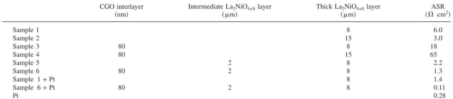
ASR values at 800°C.— The ASR values obtained are reported in TableI. It can be seen for samples 1 and 2 that increasing the electrode thickness by a factor of 2 reduces the ASR value by half. It was shown by Barbucci et al. that for an adequate oxygen reduc-tion, electrode thicknesses ranging from 20 to 50 m are desired.18 Therefore, it is believed that further increasing the thickness of these cathodes would also decrease the ASR value. In samples 3 and 4, the addition of a CGO interlayer appears to detrimentally affect the performance, with a significant increase in the ASRs observed. The addition of CGO also mechanically affected the symmetrical cells, and delamination of the electrode layers was observed after electro-chemical testing of sample 4. Additional adhesive tests were per-formed and confirmed poor adhesion between the thick La2NiO4+␦
layer and the CGO interlayer. Therefore, the high ASR values ob-tained for samples 3 and 4 were attributed to poor adhesion between the CGO interlayer and the thick La2NiO4+␦electrode.
Table I. Calculated ASR values of cathode samples recorded at 800°C.
CGO interlayer
共nm兲 Intermediate La共m兲2NiO4+␦layer Thick La共m兲2NiO4+␦layer 共⍀ cmASR2兲
Sample 1 8 6.0 Sample 2 15 3.0 Sample 3 80 8 18 Sample 4 80 15 65 Sample 5 2 8 2.2 Sample 6 80 2 8 1.3 Sample 1 + Pt 8 1.4 Sample 6 + Pt 80 2 8 0.11 Pt 0.28
By adding an intermediate compact layer of La2NiO4+␦共samples
5 and 6兲, polarization resistances were significantly reduced. It is
believed that this is a result of the number of contact points being increased between the YSZ substrate and the porous cathode layer. This would lead to an increase in oxygen surface exchange and would therefore improve oxygen diffusion toward the electrolyte. Furthermore, in sample 6, a CGO diffusion barrier layer has been added, and there was a good adherence between the CGO interlayer and the intermediate compact La2NiO4+␦ layer. This arrangement
共sample 6兲 resulted in improved ASRs and no delamination between layers because there are more contact points between the CGO and the intermediate layer than between the CGO and only the thick cathode layer.
ASR values obtained for a symmetrical cell arrangement that incorporates an intermediate compact La2NiO4+␦layer共samples 5
and 6兲 were 2.2 and 1.3 ⍀ cm2, respectively, at 800°C. These
val-ues are lower than those previously reported for the symmetrical cells of porous La2NiO4+␦deposited on YSZ; Escudero et al.19and
Mauvy et al.12obtained ASR values from La2NiO4+␦on YSZ of 2.5
and 4 ⍀ cm2, respectively.
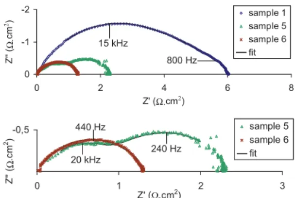
Study of Nyquist diagrams recorded at 800°C.— Nyquist dia-grams obtained for samples 1, 5, and 6 are reported in Fig.3. Po-larization resistances, capacitances, and relaxation frequencies ob-tained by fitting with an equivalent circuit model using ZView software15are collated in TableII.
Two arcs, one at medium frequency and one at low frequency, were observed for samples 1 and 5, suggesting that there were two main contributions to the polarization resistance. Based on
consid-2 μm
a)
1 μm
b)
1 μm
c)
200 nm
d)
Intermediate
La
2NiO
4+δδlayer
CGO
interlayer
2 μm
2 μm
a)
1 μm
1 μm
1 μm
b)
1 μm
c)
1 μm
1 μm
1 μm
c)
200 nm
d)
200 nm
200 nm
d)
Intermediate
La
2NiO
4+δδlayer
CGO
interlayer
Figure 1. Micrographs of cross sections of typical cathode–electrolyte
inter-faces:关共a兲 and 共b兲兴 sample 1, 共c兲 sample 5, and 共d兲 sample 6.
2 μm
thick layer
intermediate
layer
2 μm
thick layer
intermediate
layer
Figure 2. Micrographs of the cross section of a graded cathode with the
intermediate layer of La2NiO4+␦and the thick porous La2NiO4+␦layer.
-2 -1 0 0 2 4 6 8 Z' (Ω.cm2) Z' '( Ω. cm 2) sample 1 sample 5 sample 6 fit -0,5 0 1 2 3 Z' (Ω.cm2) Z' '(Ω .cm 2) sample 5 sample 6 fit 800 Hz 15 kHz 240 Hz 20 kHz 440 Hz -2 -1 0 0 2 4 6 8 Z' (Ω.cm2) Z' '( Ω. cm 2) sample 1 sample 5 sample 6 fit -0,5 0 1 2 3 Z' (Ω.cm2) Z' '(Ω .cm 2) sample 5 sample 6 fit 800 Hz 15 kHz 240 Hz 20 kHz 440 Hz
Figure 3.共Color online兲 Nyquist diagrams obtained from samples 1, 5, and
eration of the capacitance values and the literature,19,20the contri-bution at medium frequency may be due to O2− transfer at the
electrolyte–cathode interface. At low frequency, the impedance re-sponse is due to electrode reaction phenomena共adsorption, disso-ciation, oxygen reduction and O2−transfer into the cathode
thick-ness, etc.兲.19,20The benefit of introducing an intermediate compact layer of La2NiO4+␦was clearly demonstrated by the ASR reduction
observed for sample 5. It is believed that increasing the number of contact points at the electrode–electrolyte interface leads to the ob-served decrease in the contribution from the interface polarization resistance.
The addition of an 80 nm CGO layer between the YSZ electro-lyte and the intermediate compact layer of La2NiO4+␦共sample 6兲
produced an impedance response composed of a single low fre-quency contribution. The addition of a CGO interlayer avoided the formation of a La2Zr2O7insulating phase and led to a significant enhancement共lowering兲 of the ASR values when deposited with a thin compact intermediate layer of La2NiO4+␦.
Effect of current collection.— Platinum paste has been used as an additional current collector on samples 1 and 6. As a reference, a symmetrical cell composed of YSZ with platinum painted electrodes was tested. The resulting ASR data are collated in TableI.
The electrochemical performance of samples 1 and 6 was signifi-cantly improved by the addition of a continuous current collection layer of platinum, with the ASR of sample 6 reduced by a factor of 10 to 0.11 ⍀ cm2at 800°C. Lalanne et al.6and Laberty et al.11 previously reported an improvement in the ASR of K2NiF4-type
electrodes by the addition of an electronic conductor such as La1−xSrxCoO3−␦at the surface of the cathode. Therefore, it is likely
that the improvement observed here is due to the insufficient elec-tronic conductivity in the electrode layer, which is enhanced by the presence of a continuous platinum current collection layer.
The ASR of a symmetrical cell with platinum electrodes is greater than that of a symmetrical cell with thick La2NiO4+␦
elec-trodes共sample 1 + Pt兲 but is worse than that of a symmetrical cell with a CGO interlayer + an intermediate La2NiO4+␦layer + a thick
La2NiO4+␦electrode共sample 6 + Pt兲. This indicates that platinum
acts not only as an electrode in this case共sample 6兲 but mainly acts as a current collector, and we notice the benefit of graded cathodes.
Conclusions
The symmetrical cells of YSZ with graded cathodes based on lanthanum nickelate 共La2NiO4+␦兲 with a CGO interlayer between
the electrode and electrolyte have been prepared by the polymeric precursor route, and layers have been deposited by dip-coating. The graded cathodes were deposited on ZrO2–8% Y2O3substrates
be-fore heat-treatment. To evaluate the various designs, electrochemical impedance spectroscopy was performed, and a significant decrease in the ASR was achieved by incorporating an intermediate layer of compact La2NiO4+␦between the electrolyte and the porous
elec-trodes.
The lowest ASR of 0.11 ⍀ cm2at 800°C corresponds to a
sym-metrical cell consisting of an 80 nm CGO interlayer, deposited be-neath an intermediate 2 m thick La2NiO4+␦compact layer with a
fine microstructure, coated by a porous 8 m thick La2NiO4+␦layer
with a coarser microstructure and a continuous platinum current collector layer. The benefit of the CGO interlayer is to avoid the formation of the insulating phase at the YSZ–La2NiO4+␦interface,
and the addition of the intermediate compact La2NiO4+␦layer leads
to an increase in the number of contact points at the electrode/ electrolyte boundary resulting in a ready O2− transfer toward the
electrolyte.
This study underscores the importance of the derived sol–gel method for synthesizing controlled cathodic interlayers 共composi-tion and porosity兲 and optimizing the electrochemical performance of layered cathode structures.
Acknowledgments
The authors thank the French Environment and Energy Manage-ment Agency共ADEME兲 and EDF-EIFER for the financial support 共MR兲 and the EPSRC Supergen for the funding of a studentship 共RS兲.
Université Paul Sabatier assisted in meeting the publication costs of this article.
References
1. T. Tsai and S. A. Barnett, Solid State Ionics, 93, 207共1997兲.
2. A. Mai, V. A. C. Haanappel, S. Uhlenbruck, F. Tietz, and D. Stöver, Solid State
Ionics, 176, 1341共2005兲.
3. B. C. H. Steele, K. M. Hori, and S. Uchino, Solid State Ionics, 135, 445共2000兲. 4. F. Tietz, V. A. C. Haanappel, A. Mai, J. Mertens, and D. Stöver, J. Power Sources,
156, 20共2006兲.
5. G. Amow and S. J. Skinner, J. Solid State Electrochem., 10, 538共2006兲. 6. C. Lalanne, G. Prosperi, J.-M. Bassat, F. Mauvy, S. Fourcade, P. Stevens, M. Zahid,
S. Diethelm, J. Van herle, and J.-C. Grenier, J. Power Sources, 185, 1218共2008兲. 7. D. E. Vladikova, Z. B. Stoynov, A. Barbucci, M. Viviani, P. Carpanese, J. A.
Kilner, S. J. Skinner, and R. Rudkin, Electrochim. Acta, 53, 7491共2008兲. 8. H. Zhao, F. Mauvy, C. Lalanne, J.-M. Bassat, S. Fourcade, and J.-C. Grenier, Solid
State Ionics, 179, 2000共2008兲.
9. S. J. Skinner and J. A. Kilner, Solid State Ionics, 135, 709共2000兲.
10. E. Boehm, J.-M. Bassat, P. Dordor, F. Mauvy, J.-C. Grenier, and P. Stevens, Solid
State Ionics, 176, 2717共2005兲.
11. C. Laberty, Z. Feng, K. E. Swider-Lyons, and A. V. Virkar, Electrochem.
Solid-State Lett., 10, B170共2007兲.
12. F. Mauvy, C. Lalanne, J.-M. Bassat, J.-C. Grenier, H. Zhao, L. Huo, and P. Stevens,
J. Electrochem. Soc., 153, A1547共2006兲.
13. M. P. Pechini, U.S. Pat. 3,330,697共1967兲.
14. S. Castillo, R. F. Cienfuegos, M. L. Fontaine, P. Lenormand, P. Bacchin, and F. Ansart, Mater. Res. Bull., 42, 2125共2007兲.
15. www.scribner.com, last accessed September 2009. 16. J. Fleig, Solid State Ionics, 150, 181共2002兲.
17. E. Chinarro, J. R. Jurado, F. M. Figueiredo, and J. R. Frade, Solid State Ionics,
160, 161共2003兲.
18. A. Barbucci, M. Carpanese, A. P. Reverberi, G. Cerisola, M. Blanes, P. L. Cabot, M. Viviani, A. Bertei, and C. Nicolella, J. Appl. Electrochem., 38, 939共2008兲. 19. M. J. Escudero, A. Aguadero, J. A. Alonso, and L. Daza, J. Electroanal. Chem.,
611, 107共2007兲.
20. J. T. S. Irvine, D. C. Sinclair, and A. R. West, Adv. Mater., 2, 132共1990兲.
Table II. Resistances, capacitances, and relaxation frequencies obtained by modeling impedance diagrams of samples 1, 5, and 6 at 800°C.
Contribution no. 1 Contribution no. 2
ASR total 共⍀ cm2兲 R1 共⍀ cm2兲 C1 共F cm−2兲 f0_1 共kHz兲 共⍀ cmR2 2兲 C2 共F cm−2兲 f0_2 共kHz兲 Sample 1 4.06⫾ 0.06 2.6⫻ 10−6 15 1.93⫾ 0.03 1.0⫻ 10−4 0.81 5.99⫾ 0.09 Sample 5 0.72⫾ 0.02 1.1⫻ 10−5 20 1.51⫾ 0.02 4.5⫻ 10−4 0.23 2.23⫾ 0.04 Sample 6 1.33⫾ 0.03 2.8⫻ 10−4 0.43 1.33⫾ 0.03