HAL Id: hal-01004506
https://hal.archives-ouvertes.fr/hal-01004506
Submitted on 12 Feb 2017
HAL is a multi-disciplinary open access
archive for the deposit and dissemination of
sci-entific research documents, whether they are
pub-lished or not. The documents may come from
teaching and research institutions in France or
abroad, or from public or private research centers.
L’archive ouverte pluridisciplinaire HAL, est
destinée au dépôt et à la diffusion de documents
scientifiques de niveau recherche, publiés ou non,
émanant des établissements d’enseignement et de
recherche français ou étrangers, des laboratoires
publics ou privés.
3D finite element simulation to predict the induced
thermal field in case of laser cladding process and half
cylinder laser clad
Hussam El Cheikh, Bruno Courant
To cite this version:
Hussam El Cheikh, Bruno Courant. 3D finite element simulation to predict the induced thermal field
in case of laser cladding process and half cylinder laser clad. Photonics & Optoelectronics, Science
and Engineering Publishing Company, 2012, 1 (3), pp.55-59. �hal-01004506�
3D Finite Element Simulation to Predict the Induced
Thermal Field in Case of Laser Cladding Process
and Half Cylinder Laser Clad
Hussam El Cheikh
*1, Bruno Courant
2Institut de Recherche en Gén ie Civ il et Mécanique (GeM ) UMR CNRS 6183, LUNAM Un iversité de Nantes, Ecole Centrale de Nantes, France
*1
Hussam.e [email protected]; [email protected]
Abstract-- Direct Laser Fabrication (DLF) is a rapid
manufacturing process based on laser cladding technique in which parts are fabricated layer by layer. In this work, a coaxial nozzle is used to deposit 316L stainless steel on a low carbon steel substrate. In order to obtain a 3D simulation with reasonable computation time, the thermal and geometrical problems are decoupled. The clad geometry is supposed to be a half cylinder which corresponds to a suitable geometry to build a part layer by layer. The finite element method is used to simulate the heat conduction in the part during the process with a 3D modelling using the Arbitrary Langrangian-Eulerian (ALE) in (Multiphysics Comsol 3.5). This model allows predicting the temperature field in the part during the process.
Keywords-- Laser; Laser Cladding; Direct Laser Fabrication; Moving Heat Source; Finite Element Analysis; Thermal Field
I. INT RODUCTION
Direct Laser Fabrication (DLF) is a manufacturing method issue from rapid prototyping and laser technologies. Many works have been proposed to simu late the thermal fie ld induced in a material heated by a moving laser beam during the 80’s and 90’s years. In the 2000’s years many authors used these models mo re or less adapted to simu late the DLF process.
Rosenthal [1] proposed a 3D analytical function to describe the shape of the me lt pool in the case of a moving heat source above a semi-infin ite solid. El Che ikh et a l. [2] have shown that the clad geometry is not controlled by the powder distribution into the jet. They propose [3] a phenomenological circular form mode l taking into account the surface tension forces between the protecting gases, the laser clad mate ria l and the substrate material. Oliveira and al. [4] present a theoretical and experimental study of the coaxia l laser cladding process to understand relations between the process parameters and geometrical characteristics of one laser track. Picasso and Hoadley [5] proposed a two dimensional fin ite ele ment model to calculate the me lt pool shape for a known clad height. He and Mazumder [6] assumed a Gaussian distribution during the interaction between the powder feed rate and the laser beam, and Kar and Ma zu mder [7] proposed a one dimensional study for the dissolution of powder and mixing of the clad. Toyserkani and al. [8],[9] use a transient three-dimensional finite e le ment modelling to show the influence of many para meters on the laser c ladding process.
Ba mberger et a l. [10] use a simplified theoretica l mode l of Mie theory to show the influence of the injected part icles on the heat flu x and te mperature distribution. Cline and Anthony [11] found the temperature distribution in the steady-state case using the Green’s functions.
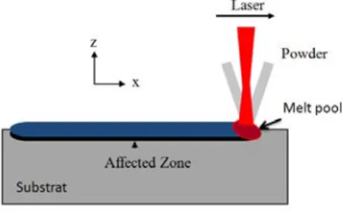
Figure 1 Model of direct laser fabrication
In this paper, a thermal simu lation, using the Arbitrary Langrangian-Eule rian (A LE) mode, is used to access to the temperature distribution in the work piece and to simu late the clad layer geometry. The clad geometry is supposed to be a half cylinder which corresponds to a suitable geometry to build a part layer by layer. The thermal simulat ion is obtained by the calculation of the conduction equation
II. EXPERIMENTAL PROCEDURES
An easy way to comply with the journal paper formatting require ments is to use this document as a template and simp ly type your text into it.
A 5 a xes speed machining is used associated with a fibre laser and a coa xia l no zzle specially designed according to the laser bea m characteristics. Argon, with a flo w rate of 3l/ min, ca rries the powder while a secondary gas, Argon with a flow rate of 5l/ min, is shaping the powder stream. This nozzle is also equipped with a cooling channel to dissipate heat.
The laser beam is focused on the substrate surface while the powder stream focused plan is 5 mm above. The dia meter of the focused powder jet is 0.6 mm and the focused laser dia meter is 0.53mm at the substrate surface.
A 316L powder, with particles size between 45 and 75 µm, is used to realize single c lad tracks. These e xperiments are rea lized with various parameters values. Three different powers (P =180, 280 and 360 W), three different powder
feed rates (Qm= 0.025, 0.05 and 0.075 g/s) and three diffe rent velocities (V= 300, 600 and 900 mm/ min) are tested.
Figure 2 shows the conic powder jet strea m geometry under the nozzle. Horizontal and vert ical image analyses are studied. On the upper part of the jet, the horizontal image analysis displays two distributions due to the coaxial form of the nozzle . Fro m the powder focus plan one distribution only rema ins. Image analysis software is used to study the powder distribution in the jet counting on the light reflection. The obtained functions are not directly the powder distribution in the jet but rather a pro jection of this distribution. Nevertheless, it can be deduced that, in the focus plan, the powder distribution is an a lmost symmetrical Gaussian type distribution. The vertical line displays the distribution along the z d irection. As shown in the image analysis, the higher concentration of the powder strea m is in the focus plan. The coaxial no zzle a llows a perfect symmetry of the part icles distribution in the stream and very few part icles outside the main t rajectories.
Figure 2 Powder distributions in the jet
The powder focus plan, at a distance l (l=3.5 mm) fro m the nozzle, is a d isc with a dia mete r dp (dp=0.6 mm). The distance work L is fixed to 5 mm. Under the powder focus plan the powder distribution remains a Gaussian type distribution. The distance between the focus plan and the substrate surface is g iven by L-l (1.5 mm) and in the interaction plan the powder stream is 2 mm in d ia meter. The laser bea m is focused on the substrate surface wh ile the focused plan for the powder strea m is 5 mm above.
III. PREDICT ION OF THE CLAD GEOMET RY
El Che ikh et a l. [2] studied the possibility to analytica lly relate the c lad geo metry and the powder distribution in the jet stream. They have established these relationships in case of three different distributions and have shown that the uniform distribution leads to semi cylindrica l geometry. They have also shown that the powder accumu lation induced by the powder distribution can’t e xp lain the c lad geometry. The c lad geo metry is controlled by the tension
forces which lead in all cases to a partial cylinder geometry. However the semi circular geo metry is a pa rticula r case suitable to build a part layer by layer. In order to obtain an analytical description of the clad geometry, the analytical formulat ion established in [2] is used. The clad height h, in the end zone (interaction between the powder jet and the laser), is proportional to the powder feed rate, and in inverse proportion to the laser speed.
) ( 2 2 2 2 r y x Vt Vr Q P h p p m e − − − = ρπ (1)
Where Pe is the powder effic iency, ρ is the material
density and rp is the radius of the interaction zone between
the powder jet and the substrate.
H being the clad height after the laser nozzle past (Zone 2 in the figure 3), it is given by:
2 2 2 2 y r Vr Q P H p p m e − = ρπ (2)
IV. THERMAL MODEL
Arbitrary Langrangian-Eule rian (A LE) method allows the combination between the Eulerian formu lation when the mesh is fixed and Langrangian formulat ion when the mesh moves with the matter to rea lize the clad laser.
Figure 3 shows the deformed mesh obtained with the ALE method under the nozzle and after it past. h is the clad laser height under the powder jet (Zone 1).
Figure 3 Deformed mesh with ALE method under and outside the laser beam
The induced therma l fie ld during the DLF process is determined solving the heat conduction equation. The fundamental behaviour of heat conduction is that a flu x Q (W/m3), representing the laser beam, heats the substrate surface.
The follo wing assumptions are taken into account in the fin ite ele ment model:
The init ial te mperature of the substrate is 300K
The heat source moves on the substrate surface at a velocity V
Thermophysical proprieties for the 316L powder and the low carbon steel substrate depend on the
temperature.
The latent heat of fusion and vaporization are assumed as 218 kJ/kg and 7600 kJ/kg respectively.
The transient temperature distribution T(x,y,z,t) is obtained from the following equation:
Q T k t T Cp +∇− ∇ = ∂ ∂ ) . ( . . ρ (3) Where Cp is the specific heat capacity [J/kg.K], k is the therma l conductivity [W/m.K], t is the time [s].
The boundary condition on the surface area irradiated by laser beam (Zone 1) is given by:
) .( . ) ( ' ) . .( Tn Q h T T0 T4 T04 K ∇ = − c − − − − εσ (4)
And on the substrate but outside the laser beam (Zone 2,3) th is condition is given by:
)
.(
.
)
(
)
.
.(
T
n
h
T
T
0T
4T
04K
∇
=
−
c−
−
−
−
ε
σ
(5)Where Q' is the flu x of energy [W/m2] Where hc is the heat convection coeffic ient [W/m2.K], where n is the norma l vector o f the surface, ε is the emissivity, σ is the Stefan-Bo ltzman constant [5.67 × 10⁻⁸ W/ m2·K4] and T0 is the ambient te mperature [K].
The init ial condition for the transient analysis is
)
,
,
(
)
0
,
,
,
(
x
y
z
T
0x
y
z
T
=
(6)The heat source is assumed to be Gaussian on the clad front: ) ( exp ' 2 2 2 0 f f r r r P a Q= − π (7) Where 2 2 y x
r= + , P0 is the ma ximu m powe r intensity,
a is the absorptivity, 2
2
f
r is the variance of the Gaussian
function.
The materia l change of state is taking into account with a Heaviside function:
)
,
(
2
)
(
x
x
flc
hs
T
T
dT
x
x
=
s+
l−
s−
f (8)Where xs is the solid value, xl the liquid value, Tf the me lting te mperature, dT is the transition temperature between solid and liquid state, flc 2hs is the Heaviside function.
TABLE IMATERIAL PROPRIETIES FOR SOLID AND LIQUID STATE Densi ty [kg/m 3] Conducti vity [W /(m.K) ] Specific heat [J/(kg.K )] Solid state 7980 90 433 Liquid state 7551 12.29 734
The density and thermal conductivity for the solid state are those of the substrate while they a re those of the 316L
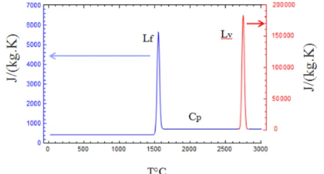
powder for the liquid state. For the specific heat Cp both the solid and liqu id state values are those of the 316L stainless steel because it’s main ly the powder that me lt and solidify (Figure 4). The latent heat is taken into consideration through the specific heat e xpression by the following function: ) , ( 2 ) (C C flc hs T T dT C Cp = ps + ps − pl − f 2 2 2 2 2 2 ) ( ) ( ) ( exp( ) ( ) ( ) ( exp( dT dT T T L dT dT T T L v v f f π π − − + − − + (9)
This effective e xp ression is given in [12]. Cps and Cpl are
the specific heat of solid and liquid state respectively, Lf and
Lv are the latent heat of fusion and vaporization respectively,
Tv is the temperature of vaporization.
The first part of this e xpression ensures the latent heat variation between the solid and liquid states. In order to take into account that heat main ly diffuses in the substrate and considering that the main part of the liquid bath corresponds to the melted powder, Cp is the solid substrate one and Cpl
the me lted powder one. This way a ll nodes of the mesh follow the same e xpression and so there is no need to make time consuming and comple x tests with the Arbitrary Langrangian-Eule rian (A LE) mode. The second part of this specific heat e xp ression corresponds to the latent heat involves during the melting and vaporisation phenomena. With the same intention to do not slow down the computation speed and considering that the main part of the liquid bath corresponds to the melted powder Lf and Lv are
the latent heat of fusion and vaporizat ion of the powder. The e xponential formu lation is a smooth function numerica lly more suitable.
Figure 4 Specific heat with distinction between solid and liquid state and with latent heat of fusion Lf, and vaporization Lv
V. RESULT AND DISCUSSION
The thermal simu lation of the laser cladding process shows a loca l melt ing pool. With the fin ite e le ment simu lation on Co msol, an absorptivity of 75% for the laser beam radiation is found to reproduce the form and dimensions of the melt ing pool. A mong the 27 observed cross-sections, nine can be we ll simu lated by a ha lf-cylinder. All these experimental conditions have been simu lated to validate our simulat ions.
Simu lating the 3D me lting pool during the clad process is a real challenge because it is a mult i-physics comple x
problem. The me lted depth in the substrate is a very sensitive ele ment which can be chosen to discuss the obtained results. Indeed, if one considers for e xa mple a laser speed decrease two opposite phenomenon occur. In one hand the linear deposit energy increase and so the me lted depth in the substrate is e xpected to increase but in the other hand the linear deposit powder mass increase so the clad height increase and the thermal source moves away fro m the substrate so the melted depth in the substrate is expected to decrease. This competition can lead to apparent contradictory results.
Expe rimental and simu lated depths of the melt pool are
compared in table II.
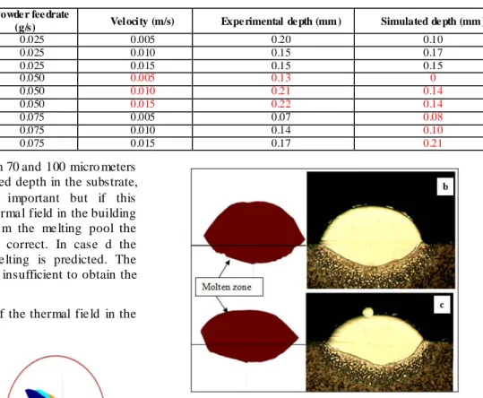
For the lowe r powder feed rate (Table II, layer number a, b and c), e xperimental results show that the speed increase leads to a lower me lted depth. The linear deposit energy phenomenon is predominant. In all other cases experimental and simu lated results show that the laser speed increase leads to a me lted depth increase. In these cases the second phenomena is predominant, the linear deposit powder mass decreases so the clad height decreases and the thermal source comes closer to the substrate and so the me lted depth in the substrate increases.
Cases b, c, g, h and i appear as very acceptable. In the
TABLE IIEXPERIMENTAL AND SIMULATED DEP TH OF THE MELTED POOL Laye r
Numbe r Power (W)
Powde r fee drate
(g/s) Velocity (m/s) Expe rimental de pth (mm) Simulated de pth (mm)
a 360 0.025 0.005 0.20 0.10 b 360 0.025 0.010 0.15 0.17 c 360 0.025 0.015 0.15 0.15 d 360 0.050 0.005 0.13 0 e 360 0.050 0.010 0.21 0.14 f 360 0.050 0.015 0.22 0.14 g 360 0.075 0.005 0.07 0.08 h 360 0.075 0.010 0.14 0.10 i 360 0.075 0.015 0.17 0.21
cases a, e and f d iffe rences between 70 and 100 micro meters are observed. Reported to the melted depth in the substrate, these diffe rences are re lative ly important but if this modelling is used to predict the therma l field in the building part or in the substrate away fro m the me lting pool the calculated thermal fie ld can still correct. In case d the diffe rence is rea l because no me lting is predicted. The refined mesh dimensions could be insufficient to obtain the good result in this case.
Figure 5 shows a simulation of the thermal fie ld in the clad during the process in case b
.
Figure 5 Melt pool view with the ALE method for the parameters (P=360 W, Qm=0.025 g/s and V=0.01 m/s)
The moving heat source is applied at the end of the depositing clad. Choosing the suitable geometry fro m the beginning, the considered comple x proble m is limited to a therma l one. The therma l fie ld determination can be solved in the 3D space with fast calculus time taking into account the real geo metry of the deposit clad. The delicate me lted depth in the substrate is in most cases well simu lated and the me lting pool geo metry can be simulated in 3D space.
Figure 6 shows in two cases a comparison between the e xperimental me lt pool and the simulated one.
Figure 6 Cross sections of experimental results on the left and simulation results on the right showing the melt pool geometry in cases b and c.
Figure 7 shows the simulated thermal field in the plane (y,z)
VI. CONCLUSION
This paper presents a therma l simulat ion of the laser cladding process using the Arbitrary Langrangian-Eu lerian (ALE) mode to represent the laser clad deposition. The conduction equation is solved to calculate temperature distribution. In most cases results show a good correlation between the calculated and observed me lt pool geo metries. The calculated thermal fie ld could be used to optimize the process parameters in case of laser cladding process or direct metal laser fabrication. More directly, it he lps to better understand the rule and intensity of the physical effects induced during the process as the laser speed effect on the melted depth. The next step is the prevision of the induced microstructures and constraints in the c lad and the substrate.
REFERENCES
[1] D. Rosenthal, "Mathematica l theory of moving sources of heat and its application to meta l t reat ments," Tans
ASME 68 pp. 849-866, 1946.
[2] H. El Cheikh, B. Courant, S. Branchu, J.Y. Hascöet, R. Gu illén, "Analysis and prediction of single laser tracks geometrica l characteristics in coa xia l laser cladding process," Opt Laser Eng, 50, 3, pp. 413-422, 2012. [3] H. El Cheikh, B. Courant, J.Y. Hascöet, R. Gu illén,
"Prediction and analytica l description of the single laser track geo metry in direct laser fabricat ion fro m p rocess parameters and energy balance reasoning," Journal of
Materials Processing Technology 212, pp. 1832-1839,
2012.
[4] U. de Olive ira, V. Ocelık, J.Th.M. De Hosson,
"Analysis of coaxia l laser cladding processing conditions," Surf. Coat. Technol. 197 pp.127– 136, 2005. [5] M. Picasso, A. F. A. Hoadley, "Finite e le ment
simu lation of laser surface treat ments including convection in the melt pool," Int. J. Numerical
methods for Heat and Fluid Flow 4 pp. 61-83, 1994.
[6] X. He, J. Ma zu mder, "Transport phenomena during direct metal deposition," Journal of Applied Physics 101 pp. 053113, 2007.
[7] J. Ma zu mder, A. Ka r, "Solid solubility in laser cladding," Journal of Metals, 39, pp. 18-23, 1987. [8] E. Toyserkani, A. Khajepour, S. Corbin, "3-D finite
ele ment modeling of laser cladding by powder injection: effects of laser pulse shaping on the process," Opt.
Lasers Eng. 41 pp. 849–867, 2004.
[9] E. Toyserkani, A. Khajepour, S. Corb in, "3-Dfinite ele ment modeling of laser cladding by powder deposition: Effects of powder feed rate and travel speed on the process," J. Laser Appl. 15 3 pp.153–160, 2004. [10] M. Ba mberger, W.D. Kaplan, B. Medres, L. Shepeleva,
"Calculat ion of process parameters for laser Alloying and cladding," Journal of Laser Applications 11 pp. 205-214, 1998.
[11] H.E Cline, T.R. Anthony, "Heat treating and melting materia l with a scanning laser or electron beam,"
Journal of Applied Physics, 48 pp.3895-3900, 1977. [12] J.M.Jouvard, A.Soveja AND N.Pie rron "Thermal
modelling of metal surface te xturing by pulsed laser", Proceedings of the European Co msol Conference 2006 in Paris, France, CD of proceedings].