Science Arts & Métiers (SAM)
is an open access repository that collects the work of Arts et Métiers Institute of
Technology researchers and makes it freely available over the web where possible.
This is an author-deposited version published in: https://sam.ensam.eu
Handle ID: .http://hdl.handle.net/10985/9670
To cite this version :
Mamoun FELLAH, Mohamed LABAIZ, Omar ASSALA, Leila DEKHIL, N. ZERNIZ, Alain IOST -Tribological behavior of biomaterial for total hip prosthesis - Matériaux & Techniques - Vol. 102, p.1-8 - 2014
Any correspondence concerning this service should be sent to the repository Administrator : archiveouverte@ensam.eu
Sc
ience
Arts
&
Mét
iers
(SAM)
is
an
open
access
repos
i
tory
tha
t
co
l
lec
ts
the
work
o
f
Ar
ts
e
t
Mé
t
iers
Par
isTech
researchers
and
makes
i
t
free
ly
ava
i
lab
le
over
the
web
where
poss
ib
le
.
Thisis an author-deposited version publishedin: http://sam.ensam.eu HandleID:.http://hdl.handle.net/10985/9670
To cite this version :
M. FELLAH, M. LABAÏZ, O. ASSALA, L. DEKHIL, N. ZERNIZ, A.IOST - Tribological behavior of biomaterialfortotal hip prosthesis - Matériaux & Techniques - Vol. 102, p.1-8 - 2014
Any correspondence concerningthis service should be senttothe repository Administrator: archiveouverte@ensam.eu
T
r
ibo
log
ica
l behav
ior of b
iomater
ia
l
for
tota
l h
ip prosthes
is
M
. Fe
l
lah
1,2, M
.Laba¨
ız
1, O
. Assa
la
1,L
. Dekh
i
l
3, N
.Zern
iz
4and A
.
Iost
5Abstract – Friction and wear plays an important role in determining the performance of biomaterials. To this end, the present research is carried out to understand the tribological behavior important biometallic alloy, Ti-6Al-4V under sliding contact. The friction and wear experiments were carried out using bal l-on-disc and pin-on-disc tribometers in ambient air, under different conditions of normal applied loads (3, 6 and 10 N) and sliding speeds (1, 15 and 25 mm.s−1) for 3000 m. The obtained research results revealed
the lowest coefficient of friction was 0.038 at 1 mm.s−1and 3 N) while the higher value was in the range of
0.90 at 25 mm.s−1and 3 N). Results show that the specimens have similar friction and wear performance,
although the sliding speed and applied loads are different. The tribomechanical wear, as evident from the observation of abrasion, adhesion and cracking, is the predominant wear mechanism.
Key words: Tribological behavior / friction coefficient / wear / biomaterial / Ti-6Al-4V
1
Introduct
ion
The wide use of Ti materials for biomedical appl i-cations is constantly growing due to their specialized properties such as high specific strength, good mechan-ical properties, low elastic modulus, superior corrosion resistance, and higher biocompatibility compared with the other conventionally used metallic biomaterials [1]. These outstanding properties were a motivating force for the early offering of (α)cpand(α+β) Titanium alloys. Ti-6A1-4V alloys as well as for the more recent development of Ti-alloy compositions ofα,α+β,βand metastable βTi alloys. One of the main concerns for fur-ther development of Ti alloys for biomedical applications is undoubtedly its fretting and sliding wear resistance, when they are subjected to action of sliding and rubbing contact of articulating surfaces during their service in the body [2]. Generally, wear property can be defined as damage to a solid surface, involving progressive loss of material, due to relative motion between that surface and a contacting substance or substances. Recently main concern, for further development of biometallic implant materials, is, among others, stress transmission between hard tissue and biometallic components which are in
1Surface Engineering and Tribology Group, Laboratory of Metallurgy and Engineering Materials, BADJI Mokhtar-Annaba
University, P.O. 12, 23000 Annaba, Algeria mamoun.fellah@yahoo.fr
2Mechanical Engineering Department, ABBES Laghrour, Khenchela University, P.O 1252, 40004 Khenchela, Algeria 3Laboratory of formability of materials BADJI Mokhtar, Annaba University, P.O. 12, 23000 Annaba, Algeria 4Laboratory of Inorganic Materials Chemistry BADJI Mokhtar, Annaba University, P.O. 12, 23000 Annaba, Algeria 5ARTS ET METIERS ParisTech, MSMP, 8 Boulevard Louis XIV, 59046 Lille Cedex, France
contact since further bone degradation and bone adsorp-tion should be avoided [3,4]. Namely, great difference between bone and biometallic implant materials rigidity and other mechanical and tribological characteristics may lead to further bone loss and degradation. Fretting and sliding wear conditions lead to damage and then fracture of the passive oxide film [5–8] which could be disrupted at very low shear stresses [9]. Unfortunately, Ti is an extremely reactive metal and has a reputation for poor tribological properties [10,11] andinferior performance when compared with other implantable. In general, the friction, wear and corrosion failures are the main reasons of degradation [12] and great difference of tribological characteristics between bone and implant must be limited to increase the service life of the surgical implants and to avoid bone degradation and adsorp-tion [4]. The poor tribological properties of Ti alloys, attributed to their low resistance to plastic shearing and low mechanical stability of the passive surface oxide layer, are significant clinical problems [13–18] which may lead to the premature removal of the prostheses. Therefore, it is of great interest to enhance the surface friction and wear resistance of orthopedic Ti alloys inside the human body that will increase the longevity
Table1.Chemical composition, hardness and microstructure of the metallic material studied.
Ti C Mo Ta Fe Al Nb V Bal 0.03 0.01 – 0.10 6.7 – 4.2 Hardness: 360±10 HV Microstructure: 80%α20%β
oftotaljoint components. Muchresearchefforts have been devoted to study and improve the performance in terms of the wear behavior of the biomedical Ti alloys. Var i-ous proper surface modification techniques, such as ion implantation, TiN coating, thermal oxidation, compos i-tion adjustment and selection of appropriate thermal and thermomechanical processing procedures have thus been proposed to improve the wear resistance by changing the nature of the surface[19–21]. The aim ofthe presentstudy was to study the friction and wear behavior of Ti6Al4V alloy under different condition of applied load and sl id-ing speed. The tests were carried out under dry sliding conditions against a 100Cr6 “counter material”.
2 Mater
ia
ls and methods
2.1 Materials characterization
The material used in this study is the Ti-6Al-4V as a total hip prosthesis (femoral stem), that was cut from a titanium cylindrical bar corresponding to ISO 5832-3 part 3/ 01-07-199 (supplied by ENSAM Lille, France). The chemical composition of titanium alloys used in this study is specified in Table1.
The alloy surfaces were ground with 600 SiC abra-sive papers and polished with colloidal silica since it is known that the fixation of the implant is greatly depen-dent on good mechanical interlocking between the rough surface oftheimplant andtissue[22]. All the samples were cleaned in an ultrasonic bath with acetone, ethanol, and distilled water, for 10 min in succession and then dried in hot air and saved in the dessicator till their use.
2.1.1 Surface and microstructural analysis
After etching by a solution of 3 ml HF, 6 ml HNO3 and 100 ml H2Ofor 10 s to reduce theinfluence of surface hardening, the microstructure was studied using optical microscopy (Leica DMLM). The alloys chemicals com-position presented in Table1was acquired using spec-trometer (Spectrolab) and energy-dispersive spectroscopy (EDS using PHILIPS XL 30 ESEM-FEG, and EDX IMIX-PTS). The phases presented in alloy m icrostruc-ture were identified by X-Ray Diffractometry (Intel CPS 120/Brucker AXS) using Cu Kαgenerated at 40 kV and 35 mA. Scanning electron microscopy (SEM) and en-ergy dispersive X-ray (EDX) analyses were used to study the chemical composition of investigated materials. The roughness of the samplesin 3D was studied using Surface Data Veeco: Mag 50 X, VSI mode.
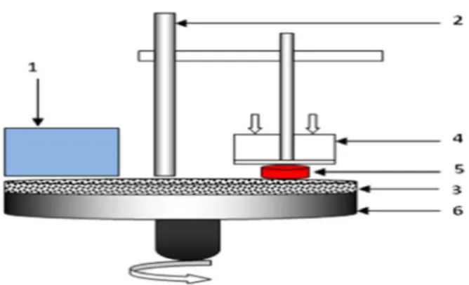
Fig. 1. Scheme of pin on disc system: 1 – Speed regulator, 2 – support, 3 – Rotating tray, 4 – load applied, 5 – Sample, 6 – retaining frame.
Fig. 2. Scheme of ball on disc contact (alternative movement).
2.2 Tribological study
Pin on disc, ball on disc and tribological tests (Figs.1 and2) were carried out using the following prosthetic materials: Ti-6Al-4V alloys, against 100Cr6 steel and abrasive Sic paper grade 320.
2.2.1 Weight loss: (Pin on disc)
The contact pair, used to study the weight loss is the sample and the 320 abrasive paper. The parameterstaken into account for this test are the appliedload (3.5 N) and the rotational speed.
The test time and sliding distance (1300 m) are kept constant, while the weight loss is determined as a the difference in the weight of the sample before and after the test. A microelectronic balance, whose accuracy is of the order 10−3g, was used for weight measurements. The samples were cleaned with acetone before each weight and the surface roughness of the test sample is measured before and after the test.
2.2.2 Friction and wear behavior (Ball on disc)
Experiments tests have been carried out, in amb i-ent air with an oscillating tribometer in accordance with
Table 2.Work condition of alternative movement wear test. Friction pairs used 100Cr6 steel/Ti-6Al-4V
Sliding speed 1, 15 and 25 mm.s−1
Applied load (N) 3, 6 and 10 N Wear track radius 5 mm 100Cr6 steel diameter 10 mm
Temperature 25◦C
Humidity 38%
ISO 7148, ASTM G99-95a and ASTM G133-95 standards (Fig.2) Samples were prepared for testing in accordance with ASTM F136-02, ASTM F86-01, ASTM E1078-02. Each specimen was thoroughly cleaned by ethyl alcohol, then cleaned in ultrasonic bath for 60 min and dried in hot air afterwards. After that, samples were cleaned in isopropyl alcohol, by staying in the solution for 60 min and dried in a hot air. Samples were stored in dessicator, prior to testing. Duration of each test was 4000 m (d is-tance of 300 m), whereat one cycle is represented by full amplitude sliding distance (half amplitude, 0.25 mm). Se-lected sliding velocities lie in the range typically found in hip joints (1, 15 and 25 mm.s−1) under different normal loads(3, 6 and 10 N). Thefriction coefficient,i.e. dynamic friction coefficient, was automatically recorded during the testing, using data acquisition software. Simultaneously, the friction coefficient curve was recorded and plotted. Test conditions are shown in Table2.
3 Resu
lts
3.1 Surface and microstructural analysis
Samples of the titanium based alloys (Fig .3)wereex-amined using (EDX) analysis. The spectra for the overall analysis are shown in Figures4and5.InthecaseofT i-6Al-4V alloy titanium, Ti peak is more pronounced than aluminum as expected in the EDX phases. Vanadium, molybdenum (Mo), nickel is also present. The chemical compositions of the studiedsample in accordance with that of a Ti-6Al-4V.
3.1.1 Microstructure
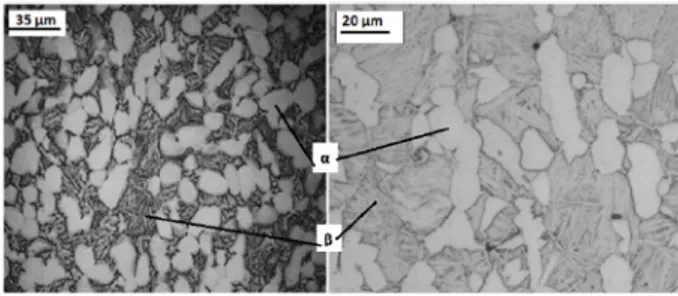
Alloy microstructure (Fig.3) consist of globular and acicularα grains (white grains) within a matrix con-taining equiaxialβ grains (dark grains). The acicular shape of theαphase is present in the Figure3in an arrangement known as basket-weave which characterizes the Widmanst¨atten structure.
3.1.2 Microhardness
Microhardness experiments (Fig. 6) were performed using universal hardness testing machine type ZHU/Z 2.5, equipped with a Vickers diamond indenter, located
Fig. 3. Optical micrographs of Ti-6Al-4V alloys.
Fig. 4. EDX spectrum of Ti-6Al-7V alloy.
Fig. 5. XRD spectrum of Ti-6Al-4V alloy.
in a room temperature of 22◦C and atmosphere of lab-oratory. Using the P–h load-penetration curves during micro hardness experiments with a 0.2 mm.min−1 load-ing speed; under a maximum load of 50 N, each test was conducted three times, and the average values were calculated automatically.
3.1.3 Roughness analysis
The studied substrates are of biomedical interest. They must therefore meet the standards imposed by the field of biomedicine particularly at the surface of the ma-terial deposited on the articular surfaces of hip prosthe-ses in which Ti-6Al-4V is the hip implant. The obtained
b
)
Fig. 6. P–h curves during micro hardness experiments.
Fig. 7. Optical 3D photos of Ti-6Al-4V after polishing. Table 3. Roughness parameters of Ti alloy after polishing.
Parameters Ra Rq Rz Rt (μm) 0.02 0.08 1.05 1.19
Ra: arithmetic average of absolute values,Rq:root mean squared,Rt: maximum height of the profile andRz is the average distance between the highest peak and lowest valley in each sampling length.
roughness of the samples (Tab.3and Fig.7), meets the standards of biomedicine, as specified in ISO 7206-2:1996 standard [23]. The roughness values Ra were 6.03 and 0.02μm for Ti-6Al-4V alloy before and after polishing, respectively.
3.2 Tribological study
3.2.1 Weight loss (contact plane)
The weight loss (Fig. 8) of titanium samples, tested at 3.5 N load, is approximately proportional to the num-ber of disc revolutions. Nevertheless, the wear was sys-tematically greater to ceramic (α-alumina) as expected in Figure8. The behavior observed for both samples sug-gests that the wear mechanism during the testis the same (abrasive wear). In the case of Ti-6Al-4V samples, its
0 0,02 0,04 0,06 0,08 0,1 0,12 0,14 0,16 0,18 0 500 1000 1500 We ig ht lo ss (g .c m-3 sliding distance(m) Ti6Al4V Ceramic
Fig. 8. Weight loss of Ti6Al4V alloys during wear sliding against abrasive paper.
weightloss was∼85% of the one observedfor the ceramic samples.
According to the Archard’s law, the volumetric loss of the material is inversely proportional to the hardness value of the material [24,25]. This implies that the higher the hardness of the material, the smaller is the volume loss. The present alloys exhibit significant difference in hardness values, so that the experimental sliding wear data correlate well with Archard’s law.
3.2.2 Friction coefficient
Dependence of Ti-6Al-4V alloys coefficient of friction (COF) on sliding distance, i.e. number of cycles, is given in Table4and from Figures9–11, are almost the same form wholes in terms of load and speed. The analysis of these curves permits to distinguish several periods or suc-cessive regimes of friction and wear:
1. The first is accommodation period, during which the friction coefficientincreases rapidly,itis the surface of the first body (the most ductile)[26]. The roughness of the sample surface is reduced by plastic deformation. 2. The second periodis characterized by a slight decrease in the friction coefficient. Probably, the third body on the track generated byfrictional wear of the steel plays a role comparable to that of a solid lubricant.
3. The third and final period corresponds to the stab i-lization of the friction coefficient up 1300 m.
It is seen from Figures10–12, that the friction coefficient displays a lower value (approx. 0.248) up to 20 m and thenincreases up to the average 0.4 value between 40 and 1000 m. The reason might be due to oxidelayerformed on titanium alloys and, therefore, the coefficient of friction showed the lower value. However, that oxide layer was torn andthen 100Cr6steel ball was completelytouched on the titanium alloy and, therefore, the friction coefficient reached a higher value (0.538).
Figures10and11displays the evolution of friction coefficient curves of Ti-6Al-4V, under different condition of appliedloads, andslidingspeeds(1, 15 and 25 mm.s−1). The results obtained showed the same form for all curves.
Table 4.Friction coefficient of Ti-6Al-4V alloy under different condition of applied loads and sliding speeds. Speed mm.s−1 Load N COF
Start COFMin COFMax COFMean
1 3 6 00.158 .064 00.038 .058 00.498 .521 00.356.297 10 0.23 0.217 0.54 0.374 15 3 6 00.229 .406 00.229 .351 00.659 .809 00.597.473 10 0.308 0.308 0.607 0.452 25 3 6 00.193 .355 00.193 .355 00.904 .754 00.489.565 10 0.372 0.349 0.648 0.476
Fig. 9. Different periods distinguished in friction curves.
A. Influence of load
Table4and Figure10represent the influence of ap-plied load on the evolution of friction coefficient, under different conditions of loads and sliding speeds. It is seen in the Figure10a at 1 mm.s−1, that the Ti-6Al-4V d is-played alower value at 6 N up 500 m, comparedto the 3 N and 10 N. The results presented in Figures10band10c show that the coefficient of friction almost has the con-vergent value under investigated conditions.
The results show in Figure10b that the average fr ic-tion coefficients were 0.59, 0.473 and 0.452for the Ti-6A l-4V alloy, at normal loads 3 N, 6 N and 10 N respectively. It is also obvious that the coefficient of friction displayed alower value (0.229, 0.351 and 0.308) up to 100 m for the Ti-6Al-4V and then it sharply increased to the average value of 0.809, until 2300 distance (m) distance.
Itis seenin Figure10c, that the Ti-6Al-4V has higher values of friction coefficient (0.754, 0.904 and 0.648). It is also obvious, that the coefficient of friction displayed a lower value at 0. 193 and 0.349, up to 50 m, and then it sharply increased to the average value of 0.75 until 1400 m.
Figure11represents the influence of applied load to the evolution of the friction coefficient of Ti-6Al-4V alloy under different loads and sliding speeds. It is seen that, the mean coefficient of samples displayed a lower value at 1 mm.s−1, and then it sharply increased to the av-erage value with increasing of sliding speed as shown in Figure12. 0 0,1 0,2 0,3 0,4 0,5 0,6 0 500 1000 1500 2000 Fn=3N Fn=6N Fn=10N 0 0,1 0,2 0,3 0,4 0,5 0,6 0,7 0,8 0,9 0 500 1000 1500 2000 2500 3000 3500 0 0,1 0,2 0,3 0,4 0,5 0,6 0,7 0,8 0,9 1 0 500 1000 1500 2000 2500 3000 3500 C OF Sliding distance(m)
a)
b)
c)
Fig. 10. Friction coefficient of titanium alloys versus sliding distance under different conditions of loads at: (a) 1 mm.s−1,
0 0,1 0,2 0,3 0,4 0,5 0,6 0,7 0,8 0,9 0 1000 2000 3000 4000 1mm/s 15 mm/s 25mm/s 0 0,1 0,2 0,3 0,4 0,5 0,6 0,7 0,8 0,9 1 0 1000 2000 3000 4000 0 0,1 0,2 0,3 0,4 0,5 0,6 0,7 0 1000 2000 3000 4000 C OF Sliding distance(m)
a)
b)
c)
Fig. 11. Friction coefficient of titanium alloys versus sliding distance under different sliding speeds at: (a) 3 N, (b) 6 N and (c) 10 N.
B. Influence of speed 3.2.3 Wear behavior
The volumetric wear rate (Fig.13) was calculated us-ing the mechanical profilom`etresurftest SJ-301. A 100Cr6 steel ball did the grinding from the sample surface, that is, abrasive wear occurred on the surface andisillustrated in Figures12and13. Volumetric wear was determined as 5.45×10−3,9.53×10−3and 12.08×10⁻³mm3N−1mm−1 for the Ti-6Al-4V at 1 mm.s−1 sliding speed under load 3, 6 and 10 N respectively. Finally, the vo lumet-ric wear was the same (convergent values) for both sl id-ing speed 15 and 25 mm.s−1between 22.35×10⁻³and 54.21×10⁻³mm3N−1mm−1for both samples. Figure13
0 0,1 0,2 0,3 0,4 0,5 0,6 0,7 0 1 2 3 4 C OF sliding speed mm.s-1 3 N 6 N 10 N
Fig. 12. Mean coefficient of friction of titanium alloys under different conditions of loads and sliding speeds.
0 10 20 30 40 50 60 1 15 25 We ar r at e ( x 10 -3m m3 N-1. m m-1) Sliding Speed mm.s-1 3 N 6 N 10 N
Fig. 13. Wear rate (mm3N−1mm−1) Ti-6Al-4V under di
f-ferent conditions.
provides the wear volume of the investigated alloy as a function of the sliding speed. The volumetric wear data reveal that the volume loss, increases as the sliding speed increases.
4 D
iscuss
ion
4.1 Friction behavior
The results of the hardness testing show that T i-6Al-4V alloy is characterized with high hardness. De-pendence between wear characteristics and hardness was reported earlier and wearvalue decreased with hard-ness increase [27]. When the properties of titanium alloy were evaluated by parameters obtained from indentation depth, depth was found to decrease with increasing con-tent of impurities [27]. The change in depth value is caused by the effect of yield strength [28] and flow stress [29]. The differences in weight loss (Fig.8)and worn surface characteristics among the two metals can be partially attributed to the differencesin hardness and the deformation process associatedwith microstructural char-acteristics. In addition, there are other factors which in-fluence material wear characteristics. Wear particles have an influence by a surface-damage mechanism [30], and the surface condition was reported to be influential in the wear characteristicsof biomaterials alloys [31]. In or-der to identify phase constitution, titanium alloys were
subjected to X-ray diffraction analysis using CuKαrad ia-tion. Presence of bothαandβphases was confirmed, and mostly the peaks corresponding to the αphase (hexag-onal closed packed) andβphase (body-centered cubic) appeared [32,33]. Microstructure of the Ti-6Al-4V alloy exhibitsαrefined two-phase structure consisting of ac i-cularαphase in prior-βgrains. Strength of the alloy is considered to stem from this refined structure.
4.2 Wear behavior
Figure13provides the wear volumelosses of the inves-tigated alloys as a function of the sliding speed. The vo l-umetric wear data reveal that the volume loss, increases as the sliding speed increases.
At higher sliding speeds, the difference in wear loss is even much higher. This can be explained by the fact that as sliding speed increases, the oxidative wear de-creases because of the reduction of the time available for the out-of-contact oxidation [34]. The oxidative wear is characterized by the formation of surface oxide islands which are continuously formed and worn away. If the ox-ide scales on the worn surface are not sufficiently sup-ported by the underlying strain-hardened material and do not adhere to the substrate, they tend to be cont inu-ously fragmented. Therefore, they are not protective and the resulting wear is severe. Since the surface of fixed specimens in the present investigation is under cont inu-ous contact, one of the reasons for poor wear resistance of investigated alloys is their inability to form protective oxide layer during wear.
The morphological analysis of the wear tracks con-firms the above results. The SEM micrographs presented in Figure14show the typical worn surface morphologies of the specimens tested at the lowest and highest sliding speed. The morphologies of the specimens worn at the in-termediate sliding speed are not shown because they show intermediate characteristics between these two extremes. On the worn surfaces of both alloys, evidences of abrasion wear can be detected in all tested specimens.
Continuous sliding marks with plastically deformed grooves and ridges are seen on the wear tracks indepen-dently of the sliding speed. However, the extent of plastic deformation or “ploughing”isfound to be smaller. Layers with consistent plastic deformations are relatively smooth at all evaluated speeds (Fig.14). Only the shallow wear grooves resulted from the penetrating of hard rigid abra-sives and subsequent scratching of the specimen surface by the penetrated abrasives can be observed. The pen-etration depth depends on the relative hardness of the abrasive with respect to the specimen surface hardness.
The SEM examination also shows that at least two wear mechanisms are operative in the Ti-6Al-4V. Ex is-tence of the flakes removed from the contact surface by delamination of material strongly suggests the occurrence of adhesive wear. During sliding, the contacting asperities experience an incremental plastic deformation, which ac-cumulates during repeated contacts [35].
d) 3N 6N 10N c) e) f) b a)
Fig. 14. SEM micrographs of alternative wear marks on T i-6Al-4V sample after the friction test at 15 mm.s−1,(a)3 N,
(b)6N(c)10Nand25mm.s−1,(d)3N,(e)6N,(
f)10N(se-vere deformation and plastic flow). Arrows indicate the sliding direction.
When a critical value of the accumulated plastic strain is attained, cracks nucleate below the surface and prop-agate parallel to the surface. As a consequence, flakes of material are detached from the surface by adhesion to the counterpart. Some of transferred material is lost, but some is re-embedded and smeared over the contact surface. In this theory of delamination [35], successively discussed and implemented by numerous authors, it is supposed that a critical plastic strainis given by the duc-tility of the material. Titanium and its alloys are chem-ically active and have a high ductility, giving rise to the strong tendency to adhesion [36].
SEM micrographs presented in Figure14show the worn surfaces of Ti-4Al-4V alloy. It is evident that frac-ture on a much larger scale is occurred and that large flakes are removed from the surface. Detailed invest iga-tion of delaminated regions reveals ridges and cracks per-pendicular to the sliding direction. Smeared areas can also be easily detected on the worn surfaces. Thesefeatures in-dicate that the wear occurs predominantly by adhesion. In this case, the adhesion overlaps the abrasion and ac-celerates the wear of the Ti-6Al-4V alloy. Occurrence of delamination is more prominent when wear tests are car-ried out at higher sliding speeds (Figs.14eand14f). The same behavior was observed by Fellah et al. [37].
5 Conc
lus
ions
The effects of friction and wear variables such as sliding speed, applied normal load, and sliding distance have been evaluated. Thefollowing conclusions are drawn based on the experimental investigations.
1. It wasfoundfrom the SEMimages that atlow applied normalload the wear trackindicates a micro fragmen-tation process, and on the other hand at high applied normal load the brittle detachment of large particles from the surface is clearly seen.
2. Large frictional fluctuations occurred, probably as a result of formation and periodic, localized fracture of atransferlayer.
3. Higher friction coefficient with more distinct value fluctuation and higher wear rate were observed at the higher sliding peed.
4. Under all investigated conditions, the friction coeffi-cient firstly decreases and then increases as a function of the sliding distance. The evolution of the friction coefficient is related to the composition of the worn surfaces.
5. The Ti-6Al-4V alloy wear mechanism transformsfrom ploughing and peeling off wear at low sliding speeds to plastic deformation and adhesive wear at elevated speed.
6. The tribomechanical wear, as evident from the ob-servation of abrasion, adhesion and cracking, is the predominant wear mechanism.
7. The observed cracking on the owned surface can be re-lated to the heavy deformation and formation of per-sistent slip bands.
Acknowledgements. This work was realized in collaboration with the mechanical laboratory of MSMP Lille in France.
References
[1] D.F. Williams, Titanium for Medical Applications. In: (Eds.) D.M. Brunette, P. Tengvall, M. Texfor, P. Thomsen, Titanium in Medicine, Springer, New York, 2001
[2] D.M. Brunette, P. Tengvall, M. Textor, et al., Titanium in medicine, Springer, Heidelberg, New York, 2001 [3] M. Niinomi, T. Hattori, S. Niwa, Material Characteristics
and Biocompatibility of Low Rigidity Titanium Alloysfor Biomedical Applications,in: M.J. Yaszemski, et al. (Eds.) D.L. Wise, Biomaterials in Orthopedics, Marcel Dekker Inc., New York, 2004, pp. 41-91
[4] L. Capitanu, J. Onisoru, A. Iarovici, et al.,Tribol. Ind. 30(2008) 23-32
[5] S.A. Brown, P.J. Hughes, K. Merrit,J. Orthopaedic Res. 6(1988) 572-579
[6] D.W. Hoeppner, V. Chandrasekaran,Wear 173(1994) 189-197
[7] L.M. Rabbe, J. Rieu, A. Lopez, et al.,Clinical Mater.15 (1994) 221-226
[8] M.H. Zhu, Z.B. Cai, W. Li, et al.,Tribol. Int.42(2009) 1360-1364,
[9] P.A. Lilley, P.S. Walker, G.W. Blunn, Wear of t ita-nium by soft tissue, in: Transactions of the 4th Word Biomaterials Congress, Berlin, 1992, pp. 227-230 [10] S. Fayeulle,Wear 107(1986) 61-70
[11] I.J. Polmear, Light Alloys, Arnold, London, 1981 [12] F. Yildiz, A.F. Yetim, A. Alsaran, et al.,Wear 267
(2009) 695-701
[13] M. Fellah, M. Laba¨ız, O. Assala, et al.,Adv. Tribol.2014 (2014) 13, DOI:10.1155/2014/451387
[14] M. Geetha, A.K. Singh, R. Asokamani,etal.,Prog. Mater. Sci. 54(2009) 397–425
[15] A. Choubey, B. Basu, R. Balasubramaniam,Mater. Sci. Eng. A379(2004) 234-239
[16] Y.L. Hao, M. Niinomi, D. Kuroda, et al.,Metall. Mater. Trans. A33(2002) 3137-3144
[17] M. Fellah, O. Assala, M. Labaiz, et al., TMS 2014 Supplemental Proceedings, John Wiley & Sons, Inc., Hoboken, NJ, USA.10.1002/9781118889879.ch32 [18] M. Fellah, O. Assala, M. Labaiz, et al.,J. Biomaterials
Nanobiotechnol.4(2013) 374-384
[19] M. Niinomi,Mater. Sci. Eng. A 243(1998) 231-236 [20] G. Manivasagam, U.K. Mudali, et al.,Corros. Rev. 21
(2003) 125
[21] S.J. Li, R. Yang, S. Li, et al.,Wear 257(2004) 869-876 [22] E. Confortoa, B.-O. Aronssonb, A. Salitoc, et al.,Mater.
Sci. Eng. C24 611-618 (2004)
[23] Implants chirurgicaux – Proth`eses partielles et totales de l’articulation de la hanche – Partie 2 : Surfaces art icu-laires constitu´ees de mat´eriaux m´etalliques, c´eramiques et plastiques, Norme internationale ISO 7206-2:1996(F) [24] J.F. Archard,J. Appl. Phys.24(1953) 981-988 [25] M. Fellah, O. Assala, M. Labaiz, et al.,Adv. Bioceram.
Porous Ceram.VI (2014) 45-57
[26]L. Avril, Elaboration de revˆetements sur acier inoxyd-able simulation de la fusion par irradiation laser car-act´erisation structurale, m´ecanique et tribologique, th`ese, ENSAM (No. d’ordre: 2003-16)
[27] T. Yoneyama, H. Doi, E. Kobayashi, et al.,Dent Japan 33(1997) 92-96
[28] A.G. Atkins, D. Tabor,J. Mech. Phys. Solids13(1965) 149-64
[29] G. Sundararajan, Y. Tirupataiah,Bull. Mater. Sci. 17 (1994) 747-770
[30] R.A. Buchanan, E.D. Rigney Jr., J.M. Williams,J. Biomed. Mater. Res.21(1987) 367-77
[31] A.U. Yap, L.F. Ong, S.H. Teoh, et al.,J. Oral Rehab.26 228-235 (1999)
[32] H. Doi, T. Yoneyama, E. Kobayashi, et al.,J. Jpn Soc. Dent. Mater. Dev.17247-5 (1998)
[33] D. Iijima, T. Yoneyama, H. Doi, et al.,Biomaterials 24 (2003) 1519-1524
[34] G. Straffelini, A. Molinari,Wear 236(1999) 328-338 [35] N.P. Suh, Update on the delamination theory of wear, in:
D.A. Rigney (Ed.), Fundamentals of Friction and Wear of Materials, ASM, Materials Park, OH, 1980, p. 43 [36] H. Dong, T. Bell,Wear 238(2000) 131-137
[37] M. Fellah, O. Assala, M. Labaiz, et al.,Tribol. Mater. Surfaces Interfaces7(2013) 135-149