HAL Id: tel-01097301
https://hal.archives-ouvertes.fr/tel-01097301
Submitted on 6 Jan 2015HAL is a multi-disciplinary open access archive for the deposit and dissemination of sci-entific research documents, whether they are pub-lished or not. The documents may come from teaching and research institutions in France or abroad, or from public or private research centers.
L’archive ouverte pluridisciplinaire HAL, est destinée au dépôt et à la diffusion de documents scientifiques de niveau recherche, publiés ou non, émanant des établissements d’enseignement et de recherche français ou étrangers, des laboratoires publics ou privés.
Distributed under a Creative Commons Attribution - NonCommercial - NoDerivatives| 4.0 International License
Surgery of the anterior segment of the eye assisted by
ultrashort pulse laser: optimisation of the parameters
with respect to tissular transparency and cell viability
Syed Asad Hussain
To cite this version:
Syed Asad Hussain. Surgery of the anterior segment of the eye assisted by ultrashort pulse laser: op-timisation of the parameters with respect to tissular transparency and cell viability. Physics [physics]. École Polytechnique, 2014. English. �tel-01097301�
http://loa.ensta.fr/ UMR 7639 Thèse
Présentée pour l’obtention du titre de
Docteur es Science de l’École Polytechnique
Spécialité : Physique
Par
Syed Asad Hussain
Surgery of the anterior segment of the eye assisted by
ultrashort pulse laser: optimisation of the parameters
with respect to tissular transparency and cell viability.
Soutenue le :
19 Septembre 2014
Jury composé de :
THURET Gilles Rapporteur
TUALLE Jean-Michel Rapporteur
DRUON Frédéric GEORGES Gaëlle
SCHANNE-KLEIN Marie-Claire
PLAMANN Karsten Directeur de thèse
Préparée au Laboratoire d’Optique Appliquée ENSTA ParisTech – École Polytechnique – CNRS UMR 7639
- 3 -
Abstract
The goal of this work was to study different microscopic and macroscopic effects that will ultimately help us to improve procedures in eye surgery assisted by ultrashort pulse lasers and most notably keratoplasty (corneal grafting), which requires laser systems which are op-erational in pathological and therefore strongly light scattering tissue. Previously, the Optique Photonique Santé (OPS) group at the Laboratoire d'Optique Appliquée (LOA) had identified 1650 nm as an optimum wavelength at which light scattering processes inside the pathological cornea are minimised.
During the present thesis, three main tasks have been addressed.
An ultrashort pulse laser system based on non-linear optical crystals has been devel-oped, optimised with respect to the requirements of laser eye surgery, and fully char-acterised. The finished set-up is compact, robust, simple and potentially qualified for clinical use.
In collaboration with a group at IESL-FORTH (Iraklion, Greece) and with the partici-pation of a previous PhD student of the group we have studied the interaction of ul-trashort pulses with water, collagen (type I) solution and porcine cornea. Data on la-ser-tissue-interaction is precious because the interaction dynamics is usually only documented for water; our results will help to develop a tissue-specific model for the interaction process.
We have investigated the interaction of the laser pulses and the effects it causes with live cells in the corneal endothelium. The preservation of endothelial cell viability is crucial notably for specific keratoplasty routines which require incisions close to the endothelium; compromised endothelial cell viability – which is likely caused by the effects of shock waves generated by optical breakdown and bubble formation – may lead to a failure of the surgical intervention. “Safe” sets of parameters concerning pulse energy and incision geometry need to be defined. We explored the maximum permitted pulse energy values at any given distance to the endothelial cells and mini-mal distances for given pulse energies and estimated the associated shock wave ampli-tudes.
- 4 -
Résumé
Le but de ce travail a été d'étudier les différents effets microscopiques et macrosco-piques susceptibles de nous aider à améliorer les procédures de chirurgie oculaire assistée par les lasers à impulsions ultra-courtes ; plus particulièrement en kératoplastie (greffe de cornée), qui nécessite des systèmes lasers opérationnels dans les tissus pathologiques et donc de diffu-sant fortement la lumière. Antérieurement, le groupe Optique Photonique Santé (OPS) du Laboratoire d'Optique Appliquée (LOA) a identifié 1650 nm comme étant une longueur d'onde optimale à laquelle les processus de diffusion de la lumière à l'intérieur de la cornée pathologique sont minimisés.
Au cours de cette thèse, trois tâches principales ont été abordées.
Un système laser à impulsions ultra-courtes à base de cristaux optiques non linéaires a été mis au point, optimisée par rapport aux exigences de chirurgie oculaire au laser, et entièrement caractérisé. Le montage achevé est compact, robuste, simple et potentiel-lement apte à un usage en clinique.
En collaboration avec un groupe de l’IESL- FORTH (Iraklion, Grèce) et avec la parti-cipation d'un ancien doctorant du groupe, nous avons étudié l'interaction des impul-sions ultra-brèves avec de l'eau, une solution de collagène (type I) et des cornées de porcs. Les données sur les interactions laser-tissu sont précieuses car la dynamique d'interaction est habituellement uniquement documentée pour l'eau; nos résultats aide-ront à élaborer un modèle spécifique de tissu pour le processus d'interaction.
Nous avons étudié l'interaction entre les impulsions laser et les effets causés sur des cellules vivantes de l'endothélium cornéen. La préservation de la viabilité des cellules endothéliales est cruciale, notamment pour les routines de kératoplastie spécifiques exigeant des incisions à proximité de l'endothélium ; la viabilité des cellules endothé-liales compromise – probablement causée par les effets des ondes de choc générées par claquage optique et la formation de bulles – peut conduire à un échec de l'interven-tion chirurgicale. Des jeux de paramètres « saufs » concernant l'énergie d'impulsion et de la géométrie de l'incision doivent être définis. Nous avons ainsi exploré les valeurs maximales autorisées de l'énergie de l'impulsion à une quelconque distance donnée des cellules endothéliales et les distances minimales pour les énergies d'impulsions données, et estimé les amplitudes des ondes de choc associées.
- 5 -
Acknowledgements
I would first like to thank Allah for everything that he has given to me. I would like to thank Karsten Plamann for giving me an opportunity to complete my PhD under his supervision. His constant guidance, support and encouragement made this dissertation possible.
Thank you also to Antoine Rousse, Carole Gratpanche, Sandrine Tricaud, Patricia Toullier, Octavie Verdun, and Lucie Huguet for their help and providing a great research environment. I am thankful to Gilles Thuret, Jean-Michel Tualle, Druon Frédéric, Georges Gaëlle, Schanne-Klein Marie-Claire (jury members) for their valuable time and suggestions.
Then I would like to thank Caroline Crotti and Laura Kowalczuk for technical guidance and assistance during my PhD especially in my early months. Thank you also to Tal Marciano for his scientific discussion and the great time that we spend together. A big thank you to Fatima Alahyane and Zacaria Essaïdi for their help and suggestions. I admire your ability to come up with quick solutions for the various technical as well as administrative problems.
In addition, I would like to thank Stelios Tzortzakis, Dimitris G. Papazoglou and Michalis Loulakis for their help on our experiment on Dynamics of fs pulse interaction with corneal tissue and a collagen (type I) solution. Without their razor sharp knowledge of the field the experiment may not be possible. Thanks also to Marc Hanna for his advice and help for our parametric amplification and generation setup.
Thanks to Florent Deloison and Hélène Desrus for their time and interest during my whole stay at ALPhANOV.
I also would like to thank Arnaud Dubois, Philippe Gain, Zhiguo He, Valeria Nuzzo, Donald Peyrot, Michèle Savoldelli, Iman Aloulou, Isabelle Tang, Mikael Guedj, Maxence Le Sourd, Charles Chalbot, Smail Khelifati, Jean-Pascal Caumes, Denis Tregoat, Florent Guichard, and Antoine Federici who have helped me on various occasions on various aspects during the past three years.
I have to specially thank Mickaël Martinez and Jean-Lou Charles for helping me on various technical problems involving mechanics in my experiments.
I would like to thank the École Polytechnique graduate school for providing me funding for my PhD, LaserLab for funding our experiment at UNIS Heraklion, Greece. The seventh framework programme of the European Union for funding the acquisition of an infrared cam-era through their NEXPRESSO program.
At the end, I like to thank my family and friends for their support, prayers and encouragement in all my endeavours.
- 6 -
Table of contents
INTRODUCTION ...16 SCIENTIFIC OBJECTIVES ...17 THESIS PLAN ...18 CHAPTER I ...20ANATOMY AND OPTICAL PROPERTIES OF THE CORNEA ...20
1.1 THE HUMAN EYE ...21
1.2 THE ANATOMY OF THE CORNEA ...23
1.2.1 Epithelium...24 1.2.2 Bowman’s layer ...24 1.2.3 Stroma ...25 1.2.4 Dua’s layer ...27 1.2.5 Descemet’s membrane ...27 1.2.6 Endothelium ...27
1.3 OPTICAL PROPERTIES OF CORNEA ...28
1.3.1. Refractive index ...28
1.3.2. Birefringence ...29
1.3.3. Transmission and scattering ...29
1.4 ANATOMICAL DIFFERENCES BETWEEN HUMAN AND PORCINE CORNEAS ...34
1.5 SURGICAL ROUTINES FOR THE ANTERIOR SEGMENT OF THE EYE ASSISTED BY ULTRASHORT LASER PULSES ...35
1.6 CONCLUSION ...37
CHAPTER II ...38
ULTRASHORT PULSE LASERS AND OPTICAL PARAMETRIC CONVERSION ...38
2.1ULTRASHORT LASER PULSES: THEORY ...39
2.2MODE LOCKING ...40
2.2.1 Active mode locking...41
2.2.2 Passive mode locking ...41
2.3ARCHITECTURES OF ULTRASHORT PULSE LASER SYSTEMS...42
2.3.1 Long oscillator ...42
2.3.2 Chirped pulse amplification ...43
2.3.2.1 Regenerative amplifier ...44
2.3.2.2 CPA based on optical fibres ...44
2.4GAIN MEDIA...45
2.5WAVELENGTH CONVERSION BY NON-LINEAR OPTICS ...46
2.5.1 Second order non-linear susceptibility...46
2.5.2 Coupled wave equations...48
2.5.3 Non-linear optical crystals ...49
2.6PHASE MATCHING ...50
2.6.1 Birefringent phase matching ...51
2.6.2 Quasi phase matching ...51
2.7OPTICAL PARAMETRIC PROCESSES ...53
2.7.1 Optical parametric generation (OPG) ...53
2.7.2 Optical parametric amplification (OPA) ...55
- 7 -
CHAPTER III ...58
INTERACTION OF ULTRASHORT LASER PULSES WITH CORNEAL TISSUE...58
3.1MECHANISMS OF LASER-TISSUE INTERACTION ...59
3.1.1 Photochemical interaction...59
3.1.2 Photothermal interaction ...60
3.1.3 Photoablation ...60
3.1.4 Plasma induced ablation and photodisruption ...60
3.2NON-LINEAR OPTICAL BREAKDOWN IN TISSUE ...60
3.2.1 Multiphoton ionisation (MPI) ...61
3.2.2 Tunneling ...61
3.2.3 Rate equation ...63
3.2.4 Breakdown criterion ...64
3.3MECHANICAL EFFECTS ASSOCIATED WITH THE NON-LINEAR OPTICAL BREAKDOWN ...65
3.4CONCLUSION...69
CHAPTER IV ...72
OPTICAL PARAMETRIC GENERATOR AND AMPLIFYER BASED ON A PERIODICALLY POLED MAGNESIUM DOPED LITHIUM NIOBATE CRYSTAL EMITTING MICROJOULE FEMTOSECOND PULSES IN THE SHORT WAVE INFRARED ...72
4.1ABSTRACT ...72
4.2INTRODUCTION ...72
4.3OPTICAL PARAMETRIC GENERATOR (OPG) ...75
4.3.1 Experimental Setup...75
4.3.2. Results and Discussion ...76
4.4OPTICAL PARAMETRIC AMPLIFICATION (OPA) ...81
4.4.1 Experimental Setup...81
4.4.2 Results and Discussion ...82
4.5CONCLUSION...87
CHAPTER V ...88
CELL VIABILITY IN THE ENDOTHELIUM OF PORCINE CORNEA EXPOSED TO ULTRASHORT LASER PULSES AT 1030 NM. ...88
5.1ABSTRACT ...88
5.2INTRODUCTION ...88
5.3MATERIALS AND METHODS...89
5.4RESULTS AND DISCUSSION ...98
5.5CONCLUSION...105
CHAPTER VI ...106
DYNAMICS OF FS PULSE INTERACTION WITH CORNEAL TISSUE AND A COLLAGEN (TYPE I) SOLUTION ...106
6.1ABSTRACT ...106
6.2INTRODUCTION ...106
6.3EXPERIMENTAL TECHNIQUE ...107
6.3.1 Sample preparation ...107
6.3.2 Experimental set-up...108
6.4RESULTS AND DISCUSSION...109
- 8 -
CONCLUSION AND OUTLOOK ...116
A. RESULTS AND CONCLUSION ...116
Development of femtosecond laser source ...116
Cell viability in the endothelium of porcine cornea exposed to ultrashort laser pulses...117
Dynamics of fs pulse interaction with water, corneal tissue and a collagen (type I) solution ...117
B. FUTURE WORK...118
APPENDIX 1: TRANSPARENCY OF PORCINE LENS ...120
APPENDIX 2: KERR EFFECT...126
APPENDIX 3: TRANSPARENCY OF HIGH PASS FILTER ...127
APPENDIX 4: NEXPRESSO PROJECT ...128
- 10 -
List of figures
C
HAPTER
I
FIG.1.1:CROSS SECTIONAL AND EN FACE VIEW OF THE HUMAN EYE [MUS]. ...22
FIG.1.2:(A)HISTOLOGY OF HUMAN CORNEA (SCALE BAR =30 ΜM)(B) HUMAN CORNEA (MICHELE SAVOLDELLI,HOPITAL HOTEL DIEU DE PARIS)[PLA10]. ...24
FIG.1.3:PRESENCE OF KERATOCYTE INSIDE THR STROMA SCALE BAR 10 ΜM (MODIFIED FROM [SSA06]). ...25
FIG.1.4:REPRESENTATION OF THE TROPOCOLLAGEN (TC) MOLECULE (A),DIFFERENT ARCHITECTURAL LEVELS OF THE COLLAGEN STRUCTURE OF THE SCLERA (B)(MODIFIED FROM [VOG03]). ...26
FIG.1.5:LAMELLAR ORIENTATION INSIDE CORNEAL STROMA (A)[CBO05],CROSS SECTION OF CORNEA WHICH REPRESENT ORIENTATION OF CORNEAL LAMELLAR (B)(SCALE BAR1µM)[CAR]...27
FIG.1.6:ENDOTHELIAL CELLS AND THEIR PUMP AND LEAK MECHANISM [NID][GOW82]. ...28
FIG.1.7:DIFFERENCE BETWEEN CLEAR AND OEDEMATOUS CORNEA [PLA10]...30
FIG.1.8:A COMPARISON OF CLEAR AND OEDEMATOUS CORNEA.KERATOCYTES AND LAKES ARE VISIBLE IN THE OEDEMATOUS CORNEA (MICHÈLE SAVOLDELLI,HÔPITAL-HÔTEL DIEU DE PARIS). ...31
FIG.1.9:EXPERIMENTAL SET-UP TO MEASURE THE (A)CORNEA SANDWICHED BETWEEN TWO LENS PAIRS,(B) TOTAL TRANSMISSION (TT),(C) DIRECT TRANSMISSION (TD) OF TISSULAR SAMPLES.(W-HAL=HALOGEN LIGHT SOURCE)[DAP10]...32
FIG.1.10:TOTAL, DIRECT AND SCATTERING OF A 450M THICK CORNEA. ...33
FIG.1.11:PERCENT OF SCATTERING FOR DIFFERENT WAVELENGTHS AT DIFFERENT THICKNESSES [DAP10]...34
FIG.1.12:FEMTOSECOND LASER PRODUCING INCISION INSIDE CORNEA [STO]. ...35
FIG.1.13:DIFFERENT SURGICAL PROCEDURES FOR WHICH FEMTOSECOND LASERS CAN BE USE [PLA10]...36
FIG.1.14:FEMTOSECOND SYSTEMS THAT CAN BE USED FOR THE ANTERIOR SEGMENT OF THE EYE. ...37
C
HAPTER
II
FIG.2.1:MODES INSIDE THE CAVITY COVERED BY THE LASER GAIN MEDIUM (A), TEMPORAL PROFILE OF THE PULSE WHEN THE LASER IS MODE LOCKED (B)(MODIFIED FROM [UKR03]). ...41FIG.2.2:TI:SAPPHIRE OSCILLATOR BASED ON KERR LENS MODE LOCKING (MODIFIED FROM [DGE06])...42
FIG.2.3:SCHEMATIC OF MULTIPLE-PASS CAVITY (MODIFIED FROM [SHC99]). ...43
FIG.2.4:SCHEMATIC DIAGRAM FOR CHIRPED PULSE AMPLIFICATION (MODIFIED FROM [LLN95]). ...43
FIG.2.5:CHIRPED PULSE AMPLIFICATION BASED ON REGENERATIVE AMPLIFICATION. ...44
FIG.2.6:CHIRPED PULSE AMPLIFICATION BASED ON LMA FIBRE [PLA10]. ...45
FIG.2.7:INTENSITY OF THE CONVERTED OPTICAL INTENSITY VERSUS CRYSTAL LENGTH (A) PHASE MATCHING,(B) QUASI-PHASE MATCHING SCHEMES AND (C) NO PHASE MATCHING. ...51
FIG.2.8:PERIODIC POLING FOR QUASI PHASE MATCHING.IN ORDER TO COMPENSATE THE PHASE SHIFT OF Π THE FERRO-ELECTRIC DOMAINS SHOULD BE FLIPPED AFTER EVERY COHERENCE LENGTH (LC). ...52
FIG.2.9:ENERGY LEVEL SCHEME FOR OPTICAL PARAMETRIC GENERATION (OPG)...53
FIG.2.10:OPTICAL PARAMETRIC GENERATION. , , AND ARE PUMP, SIGNAL AND IDLER FREQUENCIES (SEE TEXT FOR DETAIL). ...54
FIG.2.11:OPTICAL PARAMETRIC AMPLIFICATION. , , AND ARE PUMP, SIGNAL AND IDLER FREQUENCIES (SEE TEXT FOR DETAIL). ...55
- 11 -
C
HAPTER
III
FIG.3.1:CLASSIFICATION OF DIFFERENT INTERACTION REGIMES DEPENDING ON POWER DENSITY AND EXPOSURE TIME.THE CIRCLES INDICATE THE ORDERS OF MAGNITUDE OF EXPOSURE TIME AND POWER DENSITY TYPICAL FOR DIFFERENT TYPES OF INTERACTIONS.
MODIFIED FROM [MHN93]. ...59
FIG.3.2:FREE ELECTRON GENERATION (A) MULTIPHOTON IONISATION;(B) TUNNELING IONISATION;(C) COMBINED MULTIPHOTON EXCITATION AND TUNNELING (SEE TEXT).MODIFIED FROM [CBS01]. ...61
FIG.3.3:DIFFERENT PHYSICAL PROCESSES THAT CAN LEAD TO THE GENERATION OF A FREE ELECTRON.AN ELECTRON IN THE VALENCE BAND CAN BE ELEVATED INTO THE CONDUCTION BAND BY MULTIPHOTON IONISATION OR TUNNELLING.ONCE IN THE
CONDUCTION BAND, IT CAN ABSORB PHOTONS THOROUGH INVERSE BREMSSTRAHLUNG.IF ENERGY IS SUFFICIENT IT IS POSSIBLE FOR THE ELECTRON TO EXTRACT ANOTHER ELECTRON FROM THE VALANCE BAND COLLISION.THE RESULTING TWO ELECTRONS MAY REPEAT THE PROCESS AND THEREBY LEAD TO THE FURTHER GENERATION OF AN “AVALANCHE” OF FREE ELECTRONS THROUGHOUT THE VOLUME OF THE LASER FOCUS.(MODIFIED FROM [VOG05]). ...62
FIG.3.4:FRACTION OF FREE ELECTRONS (IN PERCENT) AS A FUNCTION OF TEMPERATURE. AND REPRESENT THERMALLY GENERATED ELECTRON DENSITY AND BOUND ELECTRON DENSITY [NOB10]. ...63
FIG.3.5:NUMERICALLY CALCULATED THRESHOLD RADIANT EXPOSURE FOR DIFFERENT PULSE DURATIONS [VOG05]. ...65
FIG.3.6:THRESHOLD ENERGY DENSITY FOR BUBBLE FORMATION IN WATER.(SEE TEXT FOR DETAIL, DATA FROM [NOB10]). ...66
FIG.3.7:ABLATION THRESHOLD OF PORCINE CORNEAL STROMA ASSISTED BY FEMTOSECOND LASER PULSES FOR DIFFERENT
WAVELENGTHS [GOL08]. ...67
FIG.3.8:SHOCK WAVE AMPLITUDE AT DIFFERENT TIMES IN RADIAL (R) AND AXIAL (Z) DIRECTIONS WHERE Z REPRESENT OPTICAL AXIS, DESCRIPTION OF AXIAL AND RADIAL DIRECTION USE IN THE SIMULATION(A), SHOCK WAVE AMPLITUDE IN RADIAL DIRECTION (B), SHOCK WAVE AMPLITUDE IN AXIAL DIRECTION (C)(MODIFIED FROM [VOG05]). ...68
FIG.3.9:BUBBLE DYNAMICS (A) BUBBLE SIZE << FOCAL VOLUME,(B) BUBBLE SIZE ≥ FOCAL VOLUME. ...69
C
HAPTER
IV
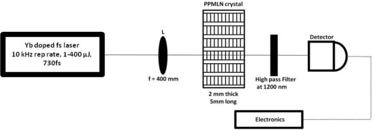
FIG.4.1:SCHEMATIC OF THE OPG SET-UP:THE LENS L FOCUSES THE PUMP BEAM INSIDE THE CRYSTAL.THE GENERATED SIGNAL PASSED THROUGH THE HIGH PASS FILTER FOLLOWED BY THE DETECTOR. ...75
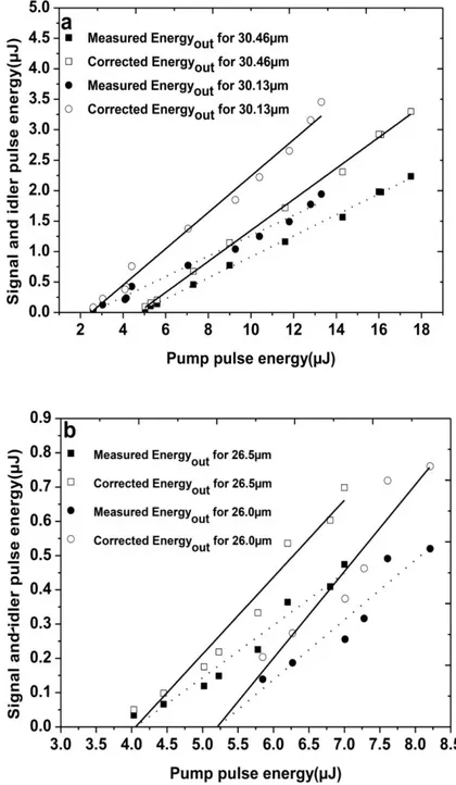
FIG.4.2:SIGNAL AND IDLER PULSE ENERGY VERSUS INPUT ENERGY MEASURED AND CORRECTED FOR TWO DIFFERENT GRATINGS ON EACH CRYSTAL: CRYSTAL A(A), CRYSTAL B(B). ...77
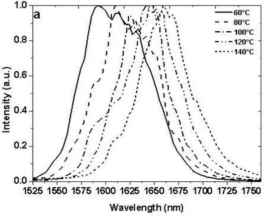
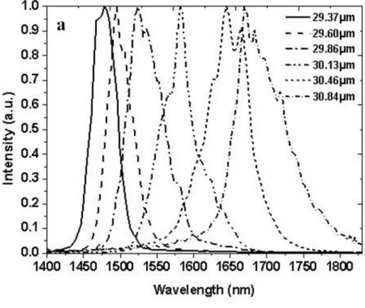
FIG.4.3(A)-(B):OPG SPECTRUM MEASURED FOR CONSTANT GRATING AT DIFFERENT TEMPERATURE:30.46 µM FOR CRYSTAL A(A) 26 µM FOR CRYSTAL B(B). ...78
FIG.4.4(A)-(B):OPG SPECTRUM MEASURED FOR DIFFERENT GRATINGS AT CONSTANT TEMPERATURE OF 100°C FOR CRYSTAL A(A) AND B(B). ...79
FIG.4.5(A)-(B):TEMPERATURE TUNING CURVES MEASURED FOR DIFFERENT GRATINGS: CRYSTAL A(29.37,29.60,29.86,30.13, 30.46,30.84 µM)(A) CRYSTAL B(24,24.5,25,25.5,26,26.5 µM)(B). ...80
FIG.4.6:SCHEMATIC OF THE OPA SET-UP:STAGE1 CONTAINS M1, BEAM SPLITTING CUBE,A1, NONLINEAR CRYSTAL (PPMLN1), HIGH PASS FILTER,A3, BANDPASS FILTER,M2,A4 AND M3.STAGE2 CONTAINS M1, BEAM SPLITTING CUBE,M4,A2, DELAY LINE,M5,M6,M7, NONLINEAR CRYSTAL (PPMLN2), WHERE M1-M7 ARE MIRRORS AND A1,A2,A4 ARE FOCUSING AND A3,A5 ARE RECOLLIMATION LENS.M2,M3,M6 ARE DICHROIC MIRRORS AND M2M3 ARE HIGHLY REFLECTIVE AT SIGNAL FREQUENCY. ...82
FIG.4.7:COMPARISON OF SLOPES WHEN DIFFERENT CONFIGURATIONS WERE CONSIDERED:OPG(SQUARE),OPA WITH BAND PASS FILTER (CIRCLE) AND OPA WITHOUT BAND PASS FILTER (TRIANGLE) DATA POINTS WERE OBTAINED FOR CRYSTAL A. ...83
FIG.4.8:SPECTRA OBTAINED IN DIFFERENT OPG AND OPA CONFIGURATIONS.OPG WITH AND WITHOUT BAND PASS FILTER (A), OPA WITH AND WITHOUT BAND PASS FILTER PLUS THE SPECTRUM OF PPMLN2 WITHOUT SEED SIGNAL FROM PPMLN1(B). 84
FIG.4.9:SPATIAL PROFILES (A) PUMP,(B) SEED WITHOUT FILTER,(C) SEED WITH FILTER,(D)OPA WITHOUT FILTER,(E)OPA WITH FILTER,(F)PPMLN2(OPG AND OPA SIGNALS WERE MEASURED AT A DISTANCE OF 400 MM AWAY FROM THE CRYSTAL). ....85
FIG.4.10:COMPARISON OF THE SLOPES FOR OPG(SQUARE) AND AMPLIFICATION DUE TO CONTINUUM GENERATION (CIRCLE)...86
- 12 -
C
HAPTER
V
FIG.5.1:SCHEMATIC OF THE EXPERIMENTAL SETUP:BE= BEAM EXPANDER,EL= EPITHELIAL LAYER,S= STROMA ,DM=DESCEMET’S MEMBRANE,E= ENDOTHELIUM,D= DISTANCE BETWEEN LASER SPOT AND ENDOTHELIUM CELLS.M1-M3 ARE MIRRORS. ...90
FIG.5.2:CONTROL CORNEA WITHOUT ANY INCISION/S OBSERVED BY THE MICROSCOPE (NIKON AZ-100)(A) USING THE THREE DIFFERENT MAGNIFICATIONS X2, X4 AND X8(FIRST, SECOND, AND THIRD ROWS).GREEN (LIVING CELLS)(B),RED (DEAD CELLS) (C),BLUE (NUCLEI OF ALL THE ENDOTHELIAL CELLS)(D).NUCLEI VISIBILITY WITH RESPECT TO DIFFERENT MAGNIFICATION(E). SCALE BAR=1500µM, WHERE THE BLACK PART IN THE FLUORESCENCE IMAGE SHOWS ABSENCE OF ENDOTHELIAL CELLS. ...92
FIG.5.3:TREATED CORNEA WITH LASER PULSES THAT MAKES A LAMELLAR INCISION OF 1000X1000M2 INSIDE THE VOLUME OF CORNEA.FLUORESCENCE IMAGE OBSERVED BY THE MICROSCOPE (NIKON AZ-100)(A),GREEN (LIVING CELLS)(B),RED (DEAD CELLS)(C),BLUE (NUCLEI OF ALL THE ENDOTHELIAL CELLS)(D).NUCLEI VISIBILITY WITH RESPECT TO DIFFERENT MAGNIFICATION (E).SCALE BAR=1500µM, WHERE THE BLACK PART IN THE FLUORESCENCE IMAGE SHOWS ABSENCE OF ENDOTHELIAL CELLS. ...94
FIG.5.4:SCHEMATIC OF THE EXPERIMENTAL SETUP:BE= BEAM EXPANDER,EL= EPITHELIAL LAYER,S= STROMA ,DM=DESCEMET’S MEMBRANE,E= ENDOTHELIUM,D= DISTANCE BETWEEN LASER SPOT AND ENDOTHELIUM CELLS.M1-M3 ARE MIRRORS. ...95
FIG.5.5:CONTROL CORNEA WITHOUT INCISION/S.THE CONTROL CORNEAS CLEARLY SHOW A UNIFORM GREEN AREA COVERED WITH LIVE CELLS WITH VERY FEW DEAD CELLS AT THE PERIPHERY WHICH ARE MAINLY DUE TO THE TREATMENT/HOLDER OF THE CORNEA. SCALE BAR=1500µM ...95
FIG.5.6:TREATED CORNEA WITH LASER PULSES THAT MAKES A LAMELLAR INCISION OF 500X2000M2 INSIDE THE VOLUME OF CORNEA (TOTAL FIVE IN NUMBER AS SHOWN IN FIGURE).FLUORESCENCE IMAGE OBSERVED BY THE MICROSCOPE (NIKON AZ-100)(A),GREEN (LIVING CELLS)(B),RED (DEAD CELLS)(C),BLUE (NUCLEI OF ALL THE ENDOTHELIAL CELLS)(D).NUCLEI VISIBILITY WITH RESPECT TO DIFFERENT MAGNIFICATION (E).SCALE BAR=1500µM, WHERE THE BLACK PART IN THE
FLUORESCENCE IMAGE SHOWS ABSENCE OF ENDOTHELIAL CELLS. ...96
FIG.5.7:DIFFERENT STEPS IN IMAGE ANALYSIS:(A) THE INCISION AREA IS DIVIDED INTO 5 PARTS;(B) ONE IMAGE IS SELECTED FROM THE SET,(C) THE GRAY SCALE HISTOGRAM SHOWS TWO PEAKS, ONE FOR THE FLUORESCENCE OF THE LIVE CELLS AND THE OTHER FOR THE RESIDUAL LIGHT INTENSITY CORRESPONDING TO THE AREA WITHOUT LIVE CELLS; A POINT WHERE IT WAS POSSIBLE TO DISTINGUISH LIVE AREA FROM THE AREA WITHOUT SURVIVING CELLS WAS CHOSEN AS THRESHOLD,(D) THE AREA OCCUPIED BY LIVE CELLS IS SHOWN IN BLACK WHILE THE AREA DEVOID OF LIVE CELLS IS SHOWN IN WHITE.THE PERCENTAGE OF THE AREA OCCUPIED BY LIVE CELLS WITH RESPECT TO THE TOTAL AREA MAY THEN BE CALCULATED.UNDER THE PLAUSIBLE ASSUMPTION OF CONSTANT CELL DENSITY OVER THE ROI, THIS GIVES THE PERCENTAGE OF SURVIVING CELLS. THE PROCESS IS THEN REPEATED FOR THE REST OF THE ROI TO OBTAIN A MEAN VALUE AND THEIR STANDARD DEVIATION. ...97
FIG.5.8:PERCENTAGE OF SURVIVING ENDOTHELIAL CELLS FOR INCISIONS PERFORMED AT PULSE ENERGIES OF 16.5µJ AT VARIABLE DISTANCES FROM THE ENDOTHELIUM (A), AVERAGE VALUES AND ESTIMATED SHOCK WAVE AMPLITUDE (B). ...99
FIG.5.9:PERCENTAGE OF SURVIVING CELLS FOR INCISIONS PERFORMED AT A DISTANCE OF 50 µM FROM THE ENDOTHELIUM AT VARIABLE PULSE ENERGIES (A), AVERAGE VALUES AND ESTIMATED SHOCK WAVE AMPLITUDE (B). ...100
FIG.5.10:DECREASE OF RADIAN EXPOSURE VERSUS DEPTH. ...101
FIG.5.11:BY MAKING INCISIONS WITH DIFFERENT ENERGY VALUES WILL RESULT IN DIFFERENT INCISION LENGTH, MAKING A FIT TO THESE VALUES WILL RESULT IN PENETRATION DEPTH [CCR13]. ...102
FIG.5.12:STRESS-WAVE AMPLITUDE AT A DISTANCE OF 6MM (IN MPA) FOR DIFFERENT PULSE DURATIONS AS A FUNCTION OF DIMENSIONLESS LASER PULSE ENERGY WHERE THE RED LINE REPRESENT THE LINEAR FIT FOR THE PULSE DURATION OF OUR LASER SOURCE [VOG05]...102
- 13 -
C
HAPTER
VI
FIG.6.1:PUMP-PROBE EXPERIMENTAL SETUPS, WITH AN INTEGRATED IN-LINE HOLOGRAPHIC MICROSCOPE FOR THE OBSERVATION OF THE TRANSIENT DYNAMICS IN THE FOCAL AREA (A) TRANSVERSE PUMP-PROBE GEOMETRY FOR THE COLLAGEN SOLUTION (B) TILTED 45O GEOMETRY IN A STRONGLY SCATTERING CORNEA SAMPLE. ...107
FIG.6.2:NORMALIZED ABSORPTION SIGNAL IN THE EXCITATION AREA (A) SPATIOTEMPORAL EVOLUTION OF THE EXCITATION IN THE CORNEA (B) COMPARATIVE TEMPORAL EVOLUTION OF THE NORMALIZED ABSORPTION SIGNAL IN THE FOCAL AREA FOR CORNEA SAMPLE AND COLLAGEN SOLUTION. ...109
FIG.6.3:COMPARATIVE POST EXCITATION TEMPORAL EVOLUTION OF THE NORMALIZED ABSORPTION SIGNAL IN THE FOCAL AREA FOR CORNEA SAMPLE AND COLLAGEN SOLUTION.THE ABSORPTION VALUES ARE NORMALIZED AT THE SECONDARY PEAK...110
FIG.6.4:SPATIAL DISTRIBUTION OF THE REFRACTIVE INDEX (REAL PART) AFTER EXCITATION OF COLLAGEN (TYPE 10.38% W) SOLUTION.PUMP PULSE : 0.3 µJ (35 FS,800 NM), DELAY ~0 PS ...111
FIG.6.5:COMPARATIVE TEMPORAL DYNAMICS AFTER IR FS EXCITATION IN WATER, CORNEA AND COLLAGEN SOLUTION.(A) LINEAR SCALES (B)LOG-LOG SCALES. ...112
FIG.6.6:DELAY OF THE APPEARANCE OF THE PEAK RELATED TO SOLVATED ELECTRONS FOR THE EXPERIMENTAL CONDITIONS OF REF. [DFA12](FOR AXICON CASE THE 400 µJ INPUT ENERGY IS COMPARABLE TO OUR EXPERIMENTAL CONDITIONS) ...112
FIG.6.7:SIGNAL SCATTERED INTENSITY.SIMILARITIES TO OUR RESULTS: A MINOR (IN THIS EXPERIMENT) PEAK ~500 FS, NO OTHER SIGNIFICANT PEAK FROM 1-10 PS [CSC02]. ...113
- 14 -
List of Tables
C
HAPTER
I
TABLE 1.1:DIMENSIONS OF THE ADULT HUMAN EYEBALL [AKK07]. ...21
TABLE 1.2:REFRACTIVE INDEX OF DIFFERENT CORNEAL LAYERS [SPA95]. ...29
TABLE 1.3:A COMPARISON BETWEEN HUMAN AND PORCINE EYEBALL (DATA OBTAINED FROM [CFA08][ISA11][LJA08][CME07] [CEW10][YZE01]). ...34
C
HAPTER
II
TABLE 2.1:DIFFERENT PROFILES THAT CAN BE USE TO DESCRIBE ULTRASHORT PULSES AND THEIR CORRESPONDING VALUES
[CRU04]. ...40
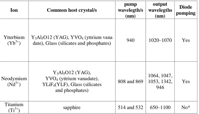
TABLE 2.2:DIFFERENT IONS CAPABLE OF PRODUCING ULTRASHORT PULSES CLOSE TO 1 µM.(*DIRECT DIODE-PUMPING OF TI:SA LASERS WAS REALISED ONLY RECENTLY AND NEEDS CONSIDERABLE FURTHER IMPROVEMENT [PWR11][CGD12]). ...46
TABLE 2.3: CONVERSION OF DIFFERENT TO . ...48
TABLE 2.4:PROPERTIES OF LINBO3 CRYSTAL [BFJ08]. ...50
Chapter III
TABLE 1.1:DIMENSIONS OF THE ADULT HUMAN EYEBALL [AKK07]. ...21
TABLE 1.2:REFRACTIVE INDEX OF DIFFERENT CORNEAL LAYERS [SPA95]. ...29
TABLE 1.3:A COMPARISON BETWEEN HUMAN AND PORCINE EYEBALL (DATA OBTAINED FROM [CFA08][ISA11][LJA08][CME07] [CEW10][YZE01]). ...34
TABLE 3.1:BREAKDOWN TEMPERATURE TCR FOR DIFFERENT PULSE DURATIONS [NOB10]...66
C
HAPTER
IV
TABLE 4.1:GRATINGS THAT ARE PRESENT ON CRYSTAL A AND B. ...75
TABLE 4.2:CONVERSION EFFICIENCIES, THE VALUE OF SIGNAL AND IDLER GENERATED BY EACH GRATING AND TRANSPARENCY OF HIGH PASS FILTER FOR EACH SIGNAL AND IDLER VALUES. ...77
TABLE 4.3:CHARACTERISTICS OF THE GENERATED SIGNAL FROM OPG AND OPA. ...86
C
HAPTER
V
TABLE 5.1:ESTIMATED SHOCKWAVE AMPLITUDES FOR THE CASE OF CONSTANT ENERGY (16.5 µJ) AND VARIABLE DISTANCE...104
TABLE 5.2:ESTIMATED SHOCKWAVE AMPLITUDE FOR THE CASE OF VARIABLE ENERGY AND CONSTANT DISTANCE OF 50µM FROM ENDOTHELIUM CELLS. ...105
- 16 -
Introduction
The eye is the sense organ of the body that allows us to see the world around us. Like other organs of the human body, the eye can encounter various diseases and injuries, some of which may be treated by surgery. Surgical techniques have been evolved with time. In today’s era, the use of ultrashort laser pulses (time duration less than 10-12 sec) is becoming common for the surgery of the anterior segment of the eye [Pla10] [Hks09]. When ultrashort laser pulses are focused into the tissue they create free electrons through non-linear ionisation processes which result in the formation of a strongly localised plasma. The threshold in radiant exposure necessary to create this plasma is of the order of 1-3 J/cm2 [Nob10][Vog05]. The plasma communicates energy to the tissue, which results in optical breakdown, the creation of a shock wave and the subsequent formation of a bubble. The gas forming the bubble is reab-sorbed by the tissue leaving a narrow incision. By placing these incisions next to each other it is possible to induce surgical cuts in three dimensions. The main difference between the use of ultrashort pulses and lasers emitting longer pulses or cw radiation for surgery is the con-finement of unwanted thermal effects which in the case of ultrashort laser do not affects the neighbouring tissue [Vog05].
The first ultrashort laser systems for eye surgery were realised in the early years 2000, when they were first used to create corneal flaps as part of the LASIK1 procedure for refrac-tive surgery. Several systems are now available of which some also offer routines for corneal grafting. In parallel, systems have been developed for cataract surgery; studies have also ad-dressed the use of ultrashort pulse lasers for glaucoma surgery and the treatment of presbyo-pia.
In recent years, the group Optique Photonique Santé at the Laboratoire d’Optique
Ap-pliquée has worked on several studies concerning the optimisation of the performance of
sur-gical lasers. The group has studied the tissue optics of the cornea in order to minimise light scattering effects compromising the laser beam quality. The group has identified a window of relative optical transparency centred at 1650 nm and has developed appropriate laser sources. The present thesis continues and completes several of these earlier studies.
1
- 17 -
Scientific objectives
Three main subjects have been covered in this thesis.
In the first project we have developed, optimised and fully characterised a compact laser system based on nonlinear wavelength conversion that is able to produce laser pulses at wavelengths in the short wavelength infra red range. In particular, this sys-tem can produce laser pulses at 1650 nm which previously had been identified as the optimum wavelength for corneal surgery; pulses at 1300 nm may be used to optimise the laser performance in the crystalline lens. This system can also be used to study the incision quality for different wavelengths.
In the second project we have studied the effect of ultashort pulses on the viability of endothelial cells as a function of pulse energy and the distance of the incisions to the cells. For this project two different sets of experiment were conducted at constant en-ergy and constant depth. In this experiment for high pulse energies (~17J) and short distances to the endothelial cells we have observed cell death. The exact mechanism of cell death still needs to be identified with certainty. We have confronted our results to estimated values of the amplitude of the shock waves which are the likely cause for cell death.
In the third project we have studied the dynamics of the interaction of femtosecond laser pulses with water, a collagen type I solution and cornea. This study has been performed at and in collaboration with the Institute of Electron Structure & Laser and with the implication of another PhD student of the group. The aim of this study was to explore the plasma creation dynamics of the focal region after the interaction with the ultrashort laser pulse. Particular attention was addressed to the identification of potential differences between the behaviour of water, often used as a “model” me-dium for tissue, a model collagen solution, and actual corneal tissue. It was found that the interaction dynamics of water are very different from that of cornea whereas the dynamics observed in the collagen solution were very similar to those in cornea. In light of our findings we suggest to use collagen type I solution as a model solution to study the dynamics inside the cornea instead of water.
- 18 -
Thesis plan
The thesis consists of six chapters.
The first chapter gives an introduction to the anatomy of the cornea and its optical prop-erties. The properties and functions of the different layers of cornea are briefly described in this chapter. At the end of the chapter we have described different surgical routines for which ultrashort laser pulses can be used.
In the second chapter we give an introduction to the theory of ultrashort pulses and dis-cuss the main principles of their practical generation. We then give an introduction into non-linear optics and non-non-linear parametric processes.
In the third chapter we first describe the interaction of ultrashort laser pulses with tissue. The main phenomena discussed are plasma creation, the formation of bubbles and the associ-ated creation of shock waves.
The fourth chapter explains in detail the characteristic of the optical parametric genera-tor and amplifier based on periodically poled lithium niobate crystals which has been devel-oped and characterised in this thesis.
In the fifth chapter we present our study of the effect of ultrashort pulse lasers on the vi-ability of endothelial cells.
In the sixth chapter we present the results of our study of the interaction dynamics of ul-trashort laser pulses inside water, collagen and cornea.
At the end of the thesis we provide a conclusion of thesis and outlines possible future developments or studies in the field.
- 20 -
Chapter I
Anatomy and optical properties of the
cornea
The main elements of the human eye, from front to back, are: the cornea, the aqueous humour, the iris, the crystalline lens, the vitreous humour and the retina. All these are held together by a white body call sclera. The eye has an ablate spheroid shape. The cornea and the crystalline lens focus the incoming light onto the retina. The cornea contributes about two-thirds to the total optical of the eye, the rest being contributed by the crystalline lens. The retina contains light sensitive rods and cones which transform incoming photons into nerve signals which are sent to the brain through the optical nerve.
The anatomy of cornea and its optical properties of the cornea such as refractive index, birefringence, transmission, and scattering are presented in detail in this chapter. We also discuss the anatomical differences of between human porcine eyes, the latter having been used as a model for the former during the present thesis. We then present different surgical routines of the anterior segment of the eye.
- 21 -
1.1 The human eye
The human eye is a complex sense organ which allows us to see the world around us. Its development starts at around the 22nd day of gestation from the neural cells that extend from the brain. The eye takes almost nine months to fully develop; complete visual acuity is achieved at 4-6 months of age [Akk07]. The eye is covered by an eyelid and a tear film. The eyelid is a thin and foldable skin presenting eyelashes. The function of the eyelid is to protect the eye from the environment whereas the lacrimal gland produces and renews the tear film; the tear duct evacuates excess amount of tear. In some conditions such as “dry eye” the tear duct needs to be closed in order to maintain humidification. Behind the eyelid the eye has an ablate spheroid shape. The typical dimensions of the eyeball are as follows [Akk07].
Anteroposterior diameter 24 mm Horizontal diameter 23.5 mm Vertical diameter 23 mm Circumference 75 mm Volume 6.5 ml Weight 7 g
Table 1.1: Dimensions of the adult human eyeball [Akk07].
Each eye takes one-fifth of a second to look from extreme left to right. The eye is moved by extraocular muscles. Figure 1.1 shows two of these muscles. The eyeball consists of three different coats which are fibrous, vascular and nervous. The fibrous coat protects the eye from the environment. 1/6 of the fibrous coat corresponds to the transparent cornea whereas the remaining opaque part is called sclera, which is the white part of the eye. The expression ‘sclera’ has a Greek root meaning ‘hard’ [Rba06]. The sclera is thicker at the back of the eye with an average thickness of around 1 to 1.35 mm; its thickness gradually dimin-ishes towards the front until it becomes 0.4 to 0.6 mm at the equator [Djj06]. The cornea (root word meaning ‘like an animal horn’) is the transparent anterior part of the fibrous coat, it is connected to the sclera through the limbus. The healthy cornea has an average thickness of 550 µm and is curved slightly outward. The transparency of the cornea is very important for vision as light passes through this tissue. The cornea is one of the tissues which were studied extensively in this work; it will be described in more detail in the following [Rba06].
- 22 -
Fig. 1. 1: Cross sectional and en face view of the human eye [Mus].
The vascular coat provides nutrition to the eyeball. It consists of three parts which are iris, ciliary body and choroid. The choroid is a spongy and pigmented structure with a thick-ness of around 0.2 mm. It consists of blood vessels, the primary function of which is to pro-vide nourishment to the photoreceptors that convert light into neural signals. Due to its high pigmentation, the choroid also absorbs the light that is not absorbed by the retina, thus reduc-ing backscatterreduc-ing and subsequent multiple reflections of the light. From the posterior to the anterior side the choroid starts to curl and becomes parallel to the cornea. This structure is called ciliary body. The ciliary body produces aqueous humour – which is the main source of nutrients and oxygen to the cornea and lens – and evacuates excess liquid. The production of aqueous humour and its drainage needs to be balanced. In case of overproduction or reduced drainage, the pressure starts to build inside the aqueous humour. In case of extreme pressure this can affect vision by compromising the function of the retina, a condition commonly known as glaucoma. This ciliary body is connected to the iris (from the Greek word for
‘rain-- 23 ‘rain--
bow’). The iris is located behind the cornea and can have different colours such as brown, gray, blue (in fig.1.1) and so forth. The black region at the centre of the iris is called pupil. The iris is attached to the dilator muscle that controls the diameter of the pupil and controls the amount of light which reaches the posterior parts of the eye that can be detected by the photoreceptors. Located behind the iris, the crystalline lens is one of the two focusing optical elements of the eye. The crystalline lens is a biconvex transparent lens enclosed within the lens capsule, which itself is attached to the ciliary muscle by the ciliary zonules. The capsule is transparent and permeable and provides nutriment to the lens through the aqueous humour. The ciliary muscle controls the shape of the crystalline lens and works against its elasticity. Changing the shape of the crystalline lens by constraining or relaxing the ciliary muscle per-mits to modulate the optical power of the lens and thus allows us to focus the image of near and far objects onto the retina. This process is called accommodation (see Appendix 1 for a detailed discussion of the lens and its transparency). The vitreous humour constitutes about two-thirds of the total volume of the eye. This chamber is filled with a gel like substance called vitreous. The vitreous is enclosed within a thin membrane that is anchored in the wall of the eyeball. Unlike the aqueous humour, the vitreous humour is not regularly renewed and may consequently lightly degenerate over time by the deposition of tissular debris. This debris can affect the light propagation through the vitreous and may cause artefacts resulting in small black spots in the visual field. Due to gravity these debris usually settle in the lower part of the eyeball. Big pieces of debris which hamper vision more strongly may be broken up into small pieces with the help of a laser. At the posterior extremity of the eyeball, the retina con-stitutes the final layer of the visual system. It contains three different layers that include layers for neurons, rods, and cones. The retina converts the light waves into neural signals that send the signal to the brain through the optic nerve. In case of damage to the optic nerve the eye is no longer capable to form images. [Rba06]
In the following sections we will present the structure of the cornea and its optical prop-erties in detail.
1.2 The anatomy of the cornea
The cornea is the first transparent layer of the eye and contributes about two thirds (2/3) to total optical power of the eye. Its formation starts around 9 weeks of gestation by mesen-chyme (a fibrous layer) and ectoderm cells [Akk07]. It is connected to the sclera through the limbus and protects the eye against the environment. Human cornea consists of six layers,
- 24 -
namely the epithelium, Bowman’s layer, the stroma, Dua’s layer, Descemet’s membrane and the endothelium (Fig. 1.2A). It typically has a diameter of around 11.5 mm in the horizontal direction and 10.5 mm in the vertical direction (Fig. 1.2B) [Cew10]. For a clear healthy cor-nea the thickness varies from 550μm at the centre and 700μm at the periphery.
Fig. 1. 2: (A) Histology of human cornea (scale bar = 30 μm) (B) human cornea. (Michèle
Savoldelli, Hôpital Hôtel Dieu de Paris) [Pla10].
1.2.1 Epithelium
The epithelium consists of five to six cell layers and has a thickness of about 50 μm. The primary function of this layer is to protect the eye from the exterior environment and to provide nutrition through the tear film which is then transported to the rest of the cornea by passive diffusion. The epithelium has the ability to regenerate itself by the proliferation of the epithelial cells. Since this layer is in direct contact to the atmosphere, any irregularity or dam-age will result in reduced visual acuity [Wsv06].
1.2.2 Bowman’s layer
The following layer is Bowman’s layer which is connected to the epithelium at the basement membrane. In the adult eye, Bowman’s layer has a typical thickness of 8 to 12 μm [MjH71] and consists of collagen fibrils (type I and III). Bowman’s layer is present in
pri-- 25 pri--
mates, humans and other animals like birds, however in some animals like pigs it is absent. At the posterior side, Bowman’s layer forms a contiguous with the stroma; consequently, Bow-man’s layer cannot be stripped easily from the stroma like Descemet’s membrane [Mks06] [Lja08] (see below).
1.2.3 Stroma
The corneal stroma is the thickest layer of the cornea with an average central thickness of about 450 μm [Mks06]. The corneal stroma contains small numbers of cells known as kera-tocytes which are scattered inside the volume of the stroma. They are formed during the de-velopment of the cornea and remain in it as a modified fibrocytes (Fig. 1.3) [Dgd06]. The rest of the stromal volume is composed of extracellular matrix (ECM) [Vog03].
Fig. 1. 3: Presence of keratocyte inside thr stroma scale bar 10 μm (Modified from [Ssa06]).
The extracellular matrix (ECM) is mostly composed of water, collagen, elastin, glyco-saminoglycans, glycoproteins, and proteins. For the case of corneal stroma it is composed of water (78%), while the dry weight of human corneal stroma was found to consist of collagen (68%), keratocytes (10%), proteoglycans (9%), and salts, glycoproteins, or other substances [Dmm84]. Collagen, which is the largest by weight, is a hydrophilic protein and composed of three alpha chains. Theses alpha chains are held together in a right handed triple helical stru c-ture and form the basic entity of the tropocollagen (TC) molecule shown in Fig 1.4A.
- 26 -
Fig. 1. 4: Representation of the tropocollagen (TC) molecule (A), Different architectural
lev-els of the collagen structure of the sclera (B) (Modified from [Vog03]).
Six TC molecules are linked by covalent cross-links around a common centre to form a microfibril. Within the fibril, these molecules are staggered approximately by one quarter of their length, which give rise to a periodical structure with regions of overlap and regions of gaps. These fibrils are immersed in a background substance which mainly consists of proteins and glycoprotiens. In the next level of the stromal architecture, these collagen fibrils then form lamellar sheets having a usual thickness of 1-2µm (Fig. 1.4B) [Vog03]. They run unin-terrupted in nasal-temporal and inferior-superior directions, making different angles with ad-jacent lamellae whose values lie between 0 and 90° (Fig.1.5) [Cbo05].
- 27 -
Fig. 1. 5: Lamellar orientation inside corneal stroma (A) [Cbo05], Cross section of cornea
which represent orientation of corneal lamellar (B) (Scale Bar1µm) [Car].
1.2.4 Dua’s layer
Dua’s layer is a layer which has been discovered only recently by Harminder Dua, in 2013. Its thickness is about 15 µm; it contains type VI collagen [Hsd13] [Hsd14]. Its function is currently under investigation.
1.2.5 Descemet’s membrane
Descemet’s membrane is the second last layer of the system sandwiched between Dua’s layer and the endothelium. It consist of several layers whose combined thickness in adults is usually 8 to 10 μm; it is mostly composed of collagen of type (VI, VIII). It can be stripped off from the stroma relatively easily during a surgical routine [Mks06].
1.2.6 Endothelium
The posterior layer of the cornea is formed by a monolayer of cells with a relatively regular polygonal mosaic structure. The cells have an average diameter of about 20 µm, a thickness of about 5 µm and each covers an area of about 250 µm2 [Mjh71] [Hfe00]. Depend-ing upon the age [Rwy85] and location on the endothelium, the density of these cells can vary [Dgd06], however, in the centre of a typical healthy adult human cornea their density is about ~ 2500-3500 cells/mm2 [Pip11] and about 10% more in the peripheral regions [Jam03]. Their
- 28 -
intercellular space contains apical tight junctions and lateral gap junctions. These junctions permit the diffusion and active pumping of small molecules through them (Fig.1.6) [Dgd06].
Fig. 1. 6: Endothelial cells and their pump and leak mechanism [Nid] [Gow82].
By means of these transport processes, the endothelial cells keep the hydration of the cornea at a constant level (78%) [NcJ03][Dmm72]. Endothelial cells do not proliferate in hu-mans. However, in case of the death of individual cells, neighbouring cells expand and cover the void area. In case of endothelial dysfunction and the loss of the liquid transport properties of the endothelium [Aly04], the corneal hydration increases and the cornea develops an oe-dema. The average distance between the collagen fibrils in the stroma then becomes higher than normal and the corneal stroma loses its regular nanostructure. Corneal oedema is associ-ated with a loss of transparency (see below).
1.3 Optical properties of cornea
1.3.1. Refractive indexAs has been described above, most of the corneal volume is occupied by the stroma which mainly contains background substance and collagen fibrils. The refractive index of cornea ( ) may be calculated as
, (Eq. 1. 1) where is the refractive index of the fibrils and is the refractive index of the back-ground substance. and are the volume fraction of both components ( + 1)
- 29 -
[Ylk04]. As the refractive index depends upon the volume of ground substance and its refrac-tive index, change in hydration will result in a change in the refracrefrac-tive index of the cornea. (The associated structural changes making it also less transparent will be discussed below). The refractive index can be measured with the help of a refractrometer. The local refractive indices of different layers and their corresponding values are given in the following table.
Layer Refractive index
Epithelium 1.401
stromal anterior 1.380
posterior surface 1.373
Table 1. 2: Refractive index of different corneal layers [Spa95]. 1.3.2. Birefringence
The corneal birefringence has been known since the early 19th century and has been studied extensively since [Dbr15] [Ljb91] [Ckh06]. This property is closely linked to the stromal architecture which is organised in lamellae of collagen fibrils (see above). Each la-mella acts as a birefringent layer with its slow axis along the collagen fibril direction [Mgd99]. As already described, lamellas run along from nasal-temporal and inferior-superior directions. Therefore, to a first approximation the overall contribution of orthogonal lamellas will cancel the contribution of each other [Rhn98]. X- ray studies show that 60% percent of lamellas are orientated within 45° sectors of inferior-superior and nasal-temporal preferred directions whereas 40% are oriented in oblique sectors that will result in a net birefringence [Ada97] [Rhn98] [Ckh06]. As the birefringence is associated with the orientation of collagen inside stroma, birefringence measurements used to detect perturbations in the volume of the stroma. For example, by using polarisation-sensitive optical coherence tomography (PS-OCT) it is possible to detect keratoconus [Egö07].
1.3.3. Transmission and scattering
On the nanometric level, the corneal stroma is composed of collagen fibrils with a refractive index higher than the surrounding medium [Pla10]. In 1957 David Maurice calculated the scattering cross section of an indiviual fibril. He concluded that the total scattering cross section of the cornea would result in an opaque tissue, when summing up the contributions of all collagen fibrils while assuming that their distribution is random. He concluded that the distribution of the collagen fibrils must exhibit a certain regularity or even,
- 30 -
as Maurice postulated, a crystal-like periodicity. In this case, interference is destructive in all directions except the forward direction, which explains corneal transparency. The absence of transparency in a pathological cornea may then be explained by the loss in structural regularity (Fig 1.7).
Fig. 1. 7: Difference between clear and oedematous cornea [Pla10].
This argument was later challenged by various researchers because the electron micro-graphs did not reveal a crystalline structure similar to the one postulated by Maurice. How-ever, subsequent work showed that crystalline periodicity is not necessary to assure transpar-ency; it is possible to prove that corneal transparency may be explained by a local short range order [Gbb71] [Rwh69]. Goldman and Benedek present the example of a shark Bowman’s membrane which shows a somewhat disordered fibril structure but yet is transparent. They further proposed that in addition to local order between the fibrils the distance between the fibrils should not exceed the wavelength of light [Jng67].
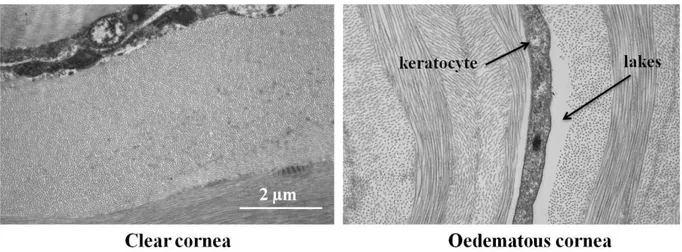
The above arguments concern scattering processes which occur at nanometric length scales. The keratocytes inside the stroma are of micrometric dimensions and give rise to a distinct scattering process, which has to be considered separately (Fig.1.3). When the cornea becomes highly oedematous an additional term due to formation of the so-called “lakes” con-tributes to the scattering by micrometric structures. Lakes are regions devoid of collagen
fi-- 31 fi--
brils which form preferentially at the intersections of collagen lamellae; they have micromet-ric thicknesses and lateral dimensions which may reach several 10 micrometres (Fig.1.8). It has been shown recently that previous history of corneal wounds is also associated with light scattering. Corneal wounds may have an impact for up to four years after the corneal accident [Rlm07].
Fig. 1. 8: A comparison of clear and oedematous cornea. Keratocytes and lakes are visible in
the oedematous cornea (Michèle Savoldelli, Hôpital-Hôtel Dieu de Paris).
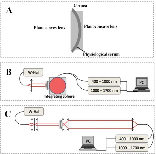
Experimentally, the transmission and scattering inside the cornea can be studied in dif-ferent ways [Nta07] [Jwa04] [Svp07] [Ddb08]. An example of a measuring approach is de-scribed below and will be discussed extensively in the later chapters. An initial study based on this approach was performed by Boettner and Wolter [Eab62]. They studied the corneal transmission by comparing data obtained from two different setups providing transmission spectra corresponding to “direct” and “total” transmission. Recently, D. Peyrot et al. from our own group used a refined approach based on the former work of Boettner and Wolter to measure the transmission and scattering properties of cornea presenting different degrees of oedema [Dap10]. The two experimental setups used in the study are shown in figure 1.9.
- 32 -
Fig. 1. 9: Experimental set-up to measure the (A) Cornea sandwiched between two lens pairs,
(B) total transmission (TT), (C) direct transmission (TD) of tissular samples. (W-Hal=Halogen light source) [Dap10].
For these experiments they sandwiched the cornea (from which the epithelium was stripped) between a pair of lenses whose radii were adapted to the natural curvature of the corneal surfaces. One planoconvex and one planoconcave lens were thus used in order to minimise surface scattering. A small amount of physiological serum was inserted between the cornea and the lens surfaces in order to match the refractive indices (Fig.1.9A). Residual re-flections from both surfaces amounted to only 4%, which may be attributed to Fresnel reflec-tion from the lens surfaces. The first experimental set-up is sensitive to the total transmission (TT) in which the spectrometer measure the transmission of the cornea from 400-1700nm
(Fig.1.9B) integrated over all angles in the forward scattering direction. The second set-up measures the spectra of the cornea in “direct” transmission (TD), that is, it is only sensitive to
photons which have experienced a negligible amount of scattering and which remain in a solid angle of 10-7 sr around the optical axis. The fraction () of the photons that have
experi-- 33 experi--
enced light scattering with trajectories outside of this solid angle can be calculated by sub-tracting direct transmission (TD) from total transmission (TT) (Fig.1.9). A typical result
ob-tained on a transparent cornea is presented in figure 1.10. The result shows that the percentage of scattered photons is high for short wavelengths, continuously decreases toward the red spectral range and becomes minimal in the near infrared (no meaningful measures are possi-ble in the wavelength range around 1400 nm because of the strong light absorption due to the water absorption band which affects this wavelength range). In conclusion, the use of near infrared wavelengths will minimize the scattering effects inside the cornea and will give su pe-rior results if used for medical applications.
Fig. 1. 10: Total, direct and scattering of a 450m thick cornea.
By repeating the same process for corneas presenting different thicknesses it is possible to estimate the amount of scattered light at different wavelengths for different degrees of oe-dema (Fig.1.11). Different degrees of oeoe-dema were produced by using a saline solution to increase the thickness of cornea (increased oedema) or by using a deturgescence process to decrease the thickness of cornea. The results that have been obtained are shown in figure 1.11. At any single wavelength, the amount of scattering is high for thick, highly oedematous neas; it decreases with thickness and presents a minimum at the natural thickness of the cor-nea. By further decreasing the thickness, light scattering increases again. Electron micr
o-- 34 o--
graphs of corneas in such a state suggest that at this point, the repulsive potential between some collagen fibrils breaks down resulting in local clusters, which result in an increased overall scattering cross section (Fig.1.11).
Fig. 1. 11: Percent of scattering for different wavelengths at different thicknesses [Dap10].
1.4 Anatomical differences between human and porcine corneas
For the experiments performed for this thesis we have mostly used porcine cornea. Por-cine corneas are not as difficult to obtain as human corneas which makes them a suitable model tissue for experimental work. However, special attention should be given in order to use them as model because one property in porcine cornea can be very different from human cornea. A comparison of porcine cornea with human cornea is presented as follows.
Human cornea Porcine cornea
Corneal thickness (mm) 550 800 to 1000
Bowman’s layer (Present/Absent) Present Absent
Endothelial cell density (cells/mm2) ~3000 ~4300
Horizontal diameter (mm) 11.5 14.9
Vertical diameter (mm) 10.5 12.4
Tensile strength (MPa) 3.8 3.7
Table 1. 3: A comparison between human and porcine eyeball (Data obtained from [Cfa08]
- 35 -
1.5
Surgical routines for the anterior segment of the eye assisted by
ultrashort laser pulses
The development of compact diode-pumped ultrashort pulse lasers in the 1990 [Cho97] made it conceivable to use these lasers in industrial and clinical applications. The mechanism of the incision made by femtosecond laser will be discussed in detail in the following two chapters. In short they create a small bubble inside the volume of the tissue; and placing these bubbles next to each other with slight overlap permits to induce incisions in three dimensions in the volume of the tissue (Fig. 1.12).
Fig. 1. 12: Femtosecond laser producing incision inside cornea [Sto].
Femtosecond lasers for ophthalmology were first commercially introduced in the early years 2000 by the company IntraLase (now owned by Abbott Medical Optics). Initially, ultrashort laser systems were used to produce flaps for the laser-assisted in situ keratomileusis (LASIK) procedure, where they replace the microkeratome (manual blade) previously used to produce the corneal flap. Nowadays, they are routinely use for the surgery of the anterior segment of the eye. Different surgical routines that can be performed by femtosecond laser systems are summarized in the following tree diagram (Fig. 1.13). Different laser systems are now available commercially whose specification can be found in literature [Pla10], in text that followed we will briefly describe routines stated in the tree diagram.
- 36 -
Fig. 1. 13: Different surgical procedures for which femtosecond lasers can be use [Pla10].
For LASIK the femtosecond systems are mainly use for creating flaps for the patient undergoing refractive correction. The flap is then lifted and stromal tissue is removed. These femtosecond systems can also be used for keratoplasty (corneal grafting), which may address the entire thickness of the pathological cornea (penetrating keratoplasty) or its anterior or pos-terior part (lamellar keratoplasty). Keratoplasty replacing only the endothelium and possibly a relatively thin adjacent layer is called endothelial keroplasty. Femtosecond systems can also be used for cataract surgery. In cataract surgery, femtosecond lasers are mainly use for capsu-lotomy (creating an incision in the lens capsule) and for fragmenting the crystalline lens. Dif-ferent systems that can provide femtosecond pulses for LASIK, keratoplasty or cataract sur-gery are shown in Fig. 1.14. Other application of femtosecond for ophthalmology especially for glaucoma is still under investigation [Pla10].
- 37 -
Fig. 1. 14: Femtosecond systems that can be used for the anterior segment of the eye.
1.6 Conclusion
In this chapter we have presented the anatomy of the eye and described in detail the structure of the cornea and its optical properties such as refractive index, birefrin-gence, transmission, and scattering.
The cornea is made up of six different layers which are epithelium, Bowman’s layer, the stroma, Dua’s layer, Descemet’s membrane and the endothelium. The local short range order of the collagen fibrils inside the corneal stroma is important for corneal transparency, the value of which should be smaller than the wavelength of light. The fluid in between the micro fibril is regulated by endothelial cells.
The refractive index of different layers of cornea is approximately equal to 1.37. The cornea is transparent in the entire visible spectral range and less transparent in the
near infrared. The scattering decrease in near infra red regime with its minimum at 1650 nm.
During the present thesis, porcine cornea has been used as a model for certain proper-ties of human cornea, however it has to be taken into account that differences exist concerning certain structural and biomechanical properties.
There are different surgical routines for the anterior segment of the eye for which fem-tosecond laser can be used. The laser-tissue interaction mechanism will be described in detail in the following chapters.
- 38 -
Chapter II
Ultrashort pulse lasers and optical
parametric conversion
Ultrashort laser pulses are high peak intensity pulses with durations below a picose c-ond (<10-12 sec). These pulses can be used for material processing, applications in research and for surgery. In contrast to laser pulses with longer pulse durations whose interaction with matter mostly involves phase transitions, ultrafast laser pulses interact via non-linear ionisa-tion processes which limits permanent modificaionisa-tions to the focal region. Ultrashort pulses can be created in a laser cavity by using an active medium with a broad gain spectrum, loc k-ing the phases of different longitudinal modes inside the cavity and managk-ing the disp ersion within the cavity. Typical oscillators emit nanojoule pulses. For application requiring more energetic pulses, pulses may be amplified using Chirped Pulse Amplification (CPA) which was originally proposed by Strickland and Mourou.
If the wavelength of the laser pulses needs to be modified, non-linear optical effects in appropriate crystals may be used. The two main approaches for nonlinear wavelength con-version are optical parametric generation and amplification. These processes are capable of creating photon pairs whose combined energy is equivalent to the pump photon. These newly create photons or laser pulses can be used for applications such as spectroscopy and surgery.
In the present chapter we present the principles and mechanisms used for the genera-tion and amplificagenera-tion of ultrashort pulses. We also present different approaches for nonlin-ear wavelength conversion based on parametric processes and present the principles of opti-cal parametric generation and amplification in detail.
- 39 -
2.1 Ultrashort laser pulses: theory
By their common definition, ultrashort laser pulses are high intensity pulses with durations below a picosecond (<10-12 sec). The short pulse duration corresponds to a broad spectrum in the frequency domain. This point can be illustrated by expressing the pulse as a Gaussian pulse. The Fourier transform of a Gaussian pulse is again a Gaussian function, the width of which is inversely proportional to the pulse duration. The Fourier transform relation between time and frequency domains can be written according to equation 2.1( - ) [Cru04].
(Eq. 2.1)
where and represent the evolution of the electric field with time and frequency.
(Eq. 2.2)
If the duration and spectral width are calculating according to the statistical relation 2.2 ( ), the duration and spectral width will be related to each other according to equation 2.3 [Cru04].
, (Eq. 2.3)
This equation is similar to quantum mechanical time energy relation and physically it means that in order to create a laser pulse with a pulse duration of (say at Full Width at Half Maximum) the spectral bandwidth needs to be sufficiently broad to satisfy the above equa-tion. In case of equality the pulse is called as Fourier-transform-limited pulse. Usually, quanti-ties at Full Width at Half Maximum (FWHM) are defined as the measuring parameters, the relation between the time and frequency bandwidth can be written as:
- 40 -
, (Eq. 2.4)
where is the frequency band width ( ) and is the time duration of the pulse and is a constant parameter the value of which depends upon the pulse shape. Different values of are summarized in table 2.1.
Function
Gaussian 0.441
Hyperbolic secant 0.315
Lorentz 0.142
Table 2. 1: Different profiles that can be use to describe ultrashort pulses and their
corre-sponding values [Cru04].
2.2 Mode locking
The mechanism and techniques used to generate ultrashort laser pulses are described for instance in [Cru04] [Mcs04] [Ukr03] [Pla10]. The part of the laser system that creates ul-trashort laser pulses is called oscillator. All systems share the following three elements: an active gain material where stimulated emission can be generated, a pump source and a set of mirrors to provide optical feedback (usually known as cavity mirrors). Typically, the oscilla-tor also contains refractive or diffractive elements to compensate for dispersion. Dispersion arises because of group velocity dispersion (GVD) that accumulates during the beam propaga-tion through different optical materials. GVD refers to the fact that the refractive index of a material is frequency dependent, lead to a broadening of the pulses. Refractive or diffractive elements can be introduced in the oscillator to compensate for this dispersion. Gratings can provide greater dispersion in comparison to prisms but also typically induce greater losses which limit their use to powerful lasers. A combined grating and prism is called “grism” and may be used to optimizing the dispersion compensation.
The mechanism to generate ultrashort pulses may be described as follows: The gain ma-terial has a finite spectral bandwidth . The laser cavity is resonant for distinct longitudinal modes which are associated with discrete frequencies . All of these modes have two main characteristics: the distribution of the corresponding electromagnetic wave needs to satisfy the boundary conditions at the cavity walls; consequently, their frequencies are separated from each other by represented as:
, where is the cavity round trip time,
![Fig. 1. 1: Cross sectional and en face view of the human eye [Mus].](https://thumb-eu.123doks.com/thumbv2/123doknet/2845025.69928/23.893.111.798.106.619/fig-cross-sectional-face-view-human-eye-mus.webp)
![Fig. 1. 11: Percent of scattering for different wavelengths at different thicknesses [Dap10]](https://thumb-eu.123doks.com/thumbv2/123doknet/2845025.69928/35.893.119.782.215.526/fig-percent-scattering-different-wavelengths-different-thicknesses-dap.webp)
![Fig. 1. 13: Different surgical procedures for which femtosecond lasers can be use [Pla10]](https://thumb-eu.123doks.com/thumbv2/123doknet/2845025.69928/37.893.118.790.140.571/fig-different-surgical-procedures-femtosecond-lasers-use-pla.webp)