HAL Id: tel-02929257
https://pastel.archives-ouvertes.fr/tel-02929257
Submitted on 3 Sep 2020HAL is a multi-disciplinary open access
archive for the deposit and dissemination of sci-entific research documents, whether they are pub-lished or not. The documents may come from teaching and research institutions in France or abroad, or from public or private research centers.
L’archive ouverte pluridisciplinaire HAL, est destinée au dépôt et à la diffusion de documents scientifiques de niveau recherche, publiés ou non, émanant des établissements d’enseignement et de recherche français ou étrangers, des laboratoires publics ou privés.
Study of the kinetics rates of low alkalinity cementitious
materials carbonation : impact on the microstructure,
the gas transport and the mechanical properties
Ekoe Kangni-Foli
To cite this version:
Ekoe Kangni-Foli. Study of the kinetics rates of low alkalinity cementitious materials carbonation : impact on the microstructure, the gas transport and the mechanical properties. Theoretical and/or physical chemistry. Université Paris sciences et lettres, 2019. English. �NNT : 2019PSLET056�. �tel-02929257�
Préparée à ESPCI Paris
(École supérieure de physique et de chimie industrielles de la ville de Paris)
Apport de matériaux cimentaires modèles à la description des
cinétiques de carbonatation de bétons bas-pH : conséquences
sur la microstructure, le transfert de gaz et les déformations
Soutenue par
Ekoé KANGNI-FOLI
Le 27 septembre 2019
Ecole doctorale n° 397
Physique
et
Chimie
des
Matériaux
Spécialité
Physico-Chimie
Composition du jury :
Barbara, LOTHENBACH Présidente Professeur, EMPA,
Jørgen, SKIBSTED
Professeur associé, Université d’Aarhus Rapporteur Véronique, BAROGHEL-BOUNY
ITPE (divisionnaire), IFSTTAR Examinatrice
Pierre, TOULHOAT
Cadre scientifique des EPIC, BRGM Examinateur
Thibault, CHARPENTIER
Directeur de recherche, CEA Examinateur
Jean-Baptiste, d’ESPINOSE de LACAILLERIE
« L’amour ne se paie qu’avec l’amour ; et les œuvres avec des œuvres » Fernando de Rojas
Un grand merci à Stéphane POYET (CEA), à Alexandre DAUZERES (IRSN) et à Céline CAU-DIT-COUMES (CEA). A toutes celles et ceux qui ont rendu ce travail possible.
Carbonation of low-pH materials
:
Consequences on the chemistry, mineralogy, microstructure,
gas transport and deformation.
i
List of tables
FIRST PART
Table 1: Compositions of the cementitious materials used for Industrial scales sealing projects (non exhaustive list).
(in kg/m3) 5
Table 2: Composition of an anhydrous and hydrated OPC using cement nomenclature. 6 Table 3: Composition of developed Low-pH materials (not exhaustive list). 9
Table 4: Properties of crystalline calcium carbonates. 12
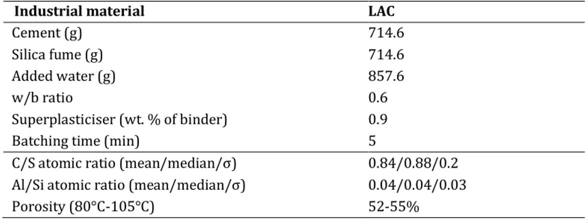
Table 5: Reported results from literature on calcium carbonate polymorphism and carbonation kinetics. 13 Table 6: Details of the formulation and some properties of the industrial LAC (50%CEM I + 50%SF) 20 SECOND PART
Chapter1
Table 1: Composition of the model pastes for 1L 37
Table 2: Composition of the reference pastes for 1L 37
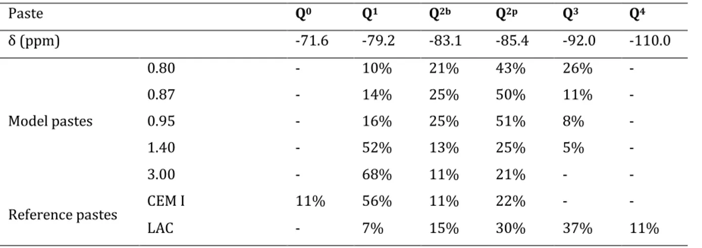
Table 3: Relative occurrence of silicate environments in synthetic and model pastes from 29Si MAS-NMR. 43
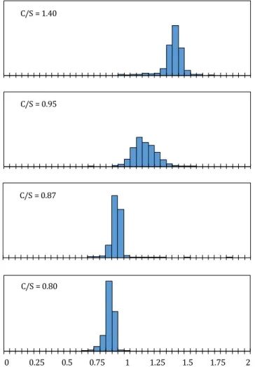
Table 4: Mean value and standard deviation of the C/S ratio distribution of the model pastes 45 Table 5: Composition and properties of the synthetic and reference pastes obtained by TGA, µCT and the buoyancy method. The C-S-H content was obtained following the method of Olson and Jennings [53]. (see Materials and
method section) 46
Chapter 2
Table 1: Nominal composition of the C-(A-)S-H that were synthesized 69 Table 2: C-A-S-Hs 27Al peak intensities, Al h refers to amorphous and ill-crystallized calcium aluminates hydrated
potentially hydroxy-AFm, C3AH6, CAH10 C2AH8, C4AH13-19. 74
Table 3: Comparison of Q3 and Q4 proportion for carbonated C(-A)-S-Hs 90
Chapter 3
Table 1: Composition of the model pastes for 1 L of paste 97
Table 2: Composition and main properties of the two model pastes 97
Table 3: Amount of calcium involved in the carbonation reaction 105
Table 4: Porosity and density of the carbonated pastes 106
ii Table 6: Volume and mass of the different phases in the carbonated paste (C/S = 1.4) 112 Table 7: volume and mass of the different phases in the non-carbonated paste (C/S = 3.0) 113 Table 8: volume and mass of the different phases in the carbonated paste (C/S = 3.0) 113 Table 9: change in solid volume (cm3/mol) induced by the carbonation of C-S-H, according to E- 15 115
Table 10: Results of the carbonation shrinkage test 116
Table 11: Distribution of 29Si MAS NMR between silicates environment of C-A-S-H and silicates in silica gel/ silica
fume, based 29Si MAS NMR spectra decomposition. C-A-S-H = (%Q1+%Q2b+%Q2p), Silica gel/silica fume =
(%Q3gel+%Q4gel). 129
Table 12: Parameters used in the 29Si MAS NMR spectra decomposition 130
iii
List of figures
FIRST PART
Figure 1: Scheme of the French deep geological facility (Cigeo project). Reproduced from www.andra.fr. ... 1
Figure 2: Sealing concept proposed for ILW-LL (modified in [1] and extracted from www.andra.fr)... 2
Figure 3: Scheme of the Tunnel Sealing Experiment (From CEBAMA project Deliverable D 1.03 [5]). ... 5
Figure 4: Scheme of the FSS experiment components [6]. ... 5
Figure 5: Cement paste equilibrium pH and associate C/S, redrawn from [8–19] and [20] is used as a model. ... 8
Figure 6: Equilibrium pH with respect to the silica content of a cement paste. (modified from[1]). ... 8
Figure 7: Molar fraction of H2CO3, HCO3- and CO32- according to the pH in water at 20°C at equilibrium, from [24]. Carbonates species’ formation constant are extracted from [21,25]. ... 11
Figure 8: Scheme of the multi-technique approach. The different types of materials and the dedicated techniques are highlighted. ... 17
Figure 9: Fabricated pastes C/S = 3: shrinkage samples (∅ = 14 mm H= 90 mm) and remaining samples (∅ = 30 mm H= 120 mm) cut to generate samples of different lengths for different carbonation terms... 19
Figure 10: Pastes covered with adhesive aluminium foil after conditioning and prior to carbonation. ... 19
Figure 11: Comparison between the pore size distribution obtained by mercury intrusion porosimetry for the uncarbonated CEM I + SF (silica fume) and the model C-S-H paste C/S = 1.4 (3 samples were analysed for each formulation) ... 20
Figure 12: Example of a logistic function fit for the grey level transition area of C/S=1.4 carbonated sample. ... 23
Figure 13: Experimental set up in climatic chamber for shrinkage measurement. ... 26
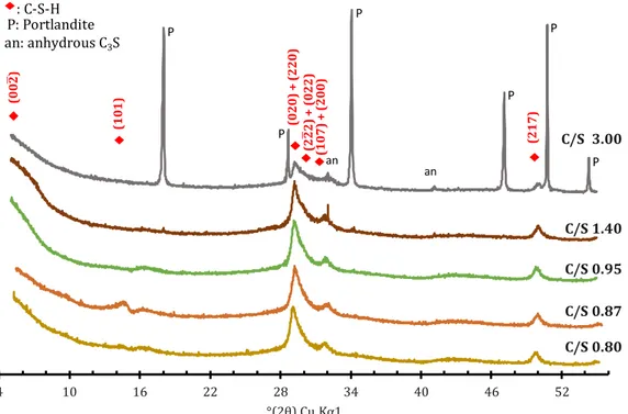
SECOND PART Chapter 1 Figure 1: XRD patterns of the synthetic pastes. As the C/S ratio decreases, Portlandite reflections progressively disappeared from the diffractogram. While still barely visible at C/S 1.4, they were absent for synthetic pastes of lower C/S ratios. C-S-H indexing was based on [64–66], ICDD files CH: 44-1481, C3S: 31-0301 ... 40
Figure 2: DTA-DTG of the model pastes. Besides losses due the removal of water within C-S-H, the typical thermal loss of portlandite was massively observed in the C3S paste. In contrast, only a residual portlandite content was evidenced in the C/S = 1.40 paste, and it totally disappeared at lower C/S ratios... 41
Figure 3: 29Si MAS-NMR spectra of the series of model synthetic pastes with varying C/S ratios and of the reference pastes. Synthetic pastes of higher C/S ratio had lower proportion of Q2 (middle chain) to Q1 (end chain) silicate coordination evidencing the expected decrease in dreierketten chain length with increasing C/S ratios. The spectra of the end members of the synthetic series where very similar to the ones of the reference pastes. The reference CEM I and LAC pastes showed Q0 and Q3/ Q4 resonances due to unreacted calcium silicates and to unreacted silica fume or amorphous silica gel products respectively. ... 42
Figure 4: SEM examination of the synthetic paste with a C/S ratio of 0.80. At the scale of the EDS mapping, the paste appeared very homogeneous in composition. ... 43
iv Figure 5: Distribution of the CaO/SiO2 ratio obtained using SEM-EDS for the C3S paste ... 44
Figure 6: Distribution of the CaO/SiO2 ratios obtained using SEM-EDS for the synthetic pastes for C/S ≤ 1.40 ... 44
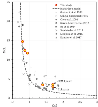
Figure 7: pH of the poral solutions of the synthetic pastes measured using the ex-situ leaching method, redrawn from [12,73–83] along with the model proposed by Haas & Nonat [72]. The pH of the pore water of the synthetic pastes satisfactorily reproduced observation reported in the literature and conformed to the predictive model. .. 45 Figure 8: PSD from mercury intrusion porosimetry for reference (right) and synthetic pastes (left).The PSD of the high C/S ratio synthetic pastes conformed to the one of an OPC (CEM I) paste, and the one for the lower C/S ratios to the one of the LAC (CEMI+SF+FA) reference paste. ... 47 Figure 9: X-ray µCT scans images of 3 samples of the synthetic pastes series. Significant cracking was observed in paste with lower C/S ratios ... 48 Figure 10: C-S-H mean chain length of the synthetic pastes (from 29Si MAS NMR) along with literature data
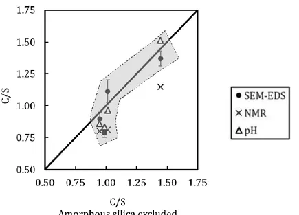
[12,40,74,75,88,90–93]. The MCL obtained for our model pastes correlated well with the MCL of the cementitious materials reported in the literature ... 49 Figure 11: Comparison of the bulk C/S ratios (excluding the silicon in the amorphous non C-S-H part of the sample, unreacted products or silica gels, estimated by 29Si NMR) with the results of SEM-EDS and with the ones expected
from modelling pH measurements (Haas and Nonat model) and NMR ones (Richardson model). ... 50 Chapter 2
Figure 1: DTA of the C-S-Hs and C-A-S-Hs of Al/Si ratios of 0.05 and 0.1 Loss associated to C(-A)-S-H between 0-725°C, and wollastonite between 725-850°C. ... 71 Figure 2: 29Si MAS NMR spectra of the C(-A)-S-Hs displayed from left to right with increasing Al/Si (0, 0.05, 0.1). 72
Figure 3: 27Al MAS-NMR of the C-A-S-Hs samples. Spectra’s surface normalized to the same value in order to allow
comparison. ... 73 Figure 4: C-S-H (left) and formation of C-A-S-H (right) by Al insertion in bridging silicates sites. The different silicates sites are highlighted, scheme adapted from [60]... 74 Figure 5: Al 3Q-MAS NMR spectra of (a) CA0.8-0.05 and (b) CA0.8-0.10. The contour lines (blue) are drawn from 10% to 100% of the maximum heights. The dotted lines represents the direction of broadening induced by an isotropic chemical shift (CS) and second-order quadrupolar induced shift (QIS) distribution. ... 75 Figure 6: CA0.8-0.05 and CA0.8-0.10 simulated and experimental MQMAS NMR spectra (left panel) and distribution of δiso plotted against CQ (right panel) are shown on figure (a) and (b), respectively... 76
Figure 7: 27Al MQMAS NMR spectra of (a) CA0.95-0.1 (b) CA1.40-0.1.* spinning sideband. ... 76
Figure 8: CA1.4-0.1 distribution of δiso plotted against CQ ... 77
Figure 9: 27Al MAS NMR spectra from 2 months after synthesis to 6 months after synthesis for (a) CA1.2-0.05/0.1 (b) CA1.4-0.05/0.1 ... 78 Figure 10: X-ray diffractograms of C-S-Hs at C/S: 0.80 and 1.40. The pristine uncarbonated states are showed together with natural (after 17 days at PCO2: 0.04%) and accelerated (after 18 days at PCO2: 3%) carbonation
products. The same polymorphs were yielded by the two types of carbonation. Regardless of the C/S ratios, carbonation was total after 18 days of accelerated carbonation ... 79 Figure 11: x-ray diffractograms of C-A-S-Hs (Al/Si = 0.1) at C/S of 0.80 and 1.40. The pristine uncarbonated states are showed together with natura.l (38 days at PCO2: 0.04%) and accelerated (34 days at PCO2: 3%) carbonation
v products. The same polymorphs are observed compared to C-S-Hs’ carbonation (see Figure 10) but a slower
carbonation kinetics is evidenced at high C/S ratio in presence of Al. ... 79
Figure 12: Intensities of observed phases at different carbonation terms for CA0.8-0.05 and CA1.4-0.05. ... 80
Figure 13: DTG of the carbonated C-A-S-Hs Al/Si=0.05, partial carbonation for CA1.40-0.05 is evidenced by reduced loss centered at 625°C... 81
Figure 14: 29Si MAS NMR spectra of non-carbonated (continued lines) and carbonated (dotted lines) (a) C-S-Hs at C/S ratios of 0.80 and 1.40 (b) C-A-S-Hs C/S: 0.80 and 1.20 at Al/Si: 0.1 and 0.05. ... 82
Figure 15: Comparison of Q3 and Q4 evolution for carbonated C(-A)-S-Hs... 82
Figure 16: 27Al MAS NMR spectra of CA0.80-0.1 and CA1.20-0.05 sounds and carbonated state. ... 83
Figure 17: 2D 27Al MQMAS spectrum of carbonated CA0.8-0.05. ... 83
Figure 18: 2D 27Al MQMAS spectrum of carbonated CA1.4-0.05. ... 83
Chapter 3 Figure 1: Principle of the gas diffusion test ... 99
Figure 2: Diffractograms of the pastes at the end of accelerated carbonation (316 and 326 days for the C-S-H and C3S pastes respectively) ... 101
Figure 3: Evidence of the presence of silica gel in the carbonated zone of the C-S-H paste (C/S = 1.4) ... 101
Figure 4: Mineralogical assemblage after accelerated carbonation (316 and 326 days for the C-S-H (top) and C3S (bottom) pastes respectively) obtained using XRD ... 102
Figure 5: CaCO3 polymorphic abundance (%wt) in the carbonated zone after accelerated carbonation (316 and 326 days for the C-S-H (top) and C3S pastes (bottom) respectively) obtained using Rietveld refinement. The vertical bar stands for the uncertainty of the quantification using Rietveld refinement (evaluated to 5%). ... 103
Figure 6: 29Si NMR spectra of the C-S-H and C3S pastes after accelerated carbonation (316 and 326 days for the C-S-H and C3S pastes respectively) ... 104
Figure 7: Quantitative mineralogical profiles obtained using TGA after accelerated carbonation (316 and 326 days for the C-S-H and C3S pastes respectively). The horizontal bar stands for the thickness of the disk that was sampled and tested using TGA. The vertical bar stands for the uncertainty of the measurement (evaluated to 5%) ... 105
Figure 8: Pore size distribution obtained using MIP after accelerated carbonation ... 106
Figure 9: Cracking pattern observed using X-µCT after accelerated carbonation (316 and 326 days for the C-S-H and C3S pastes respectively)... 107
Figure 10: View of the four zones that were observed using X-µCT in the C-S-H paste after carbonation (316 days) ... 108
Figure 11: Close-up on the zone II of the C-S-H paste and view of the cracks and discrepancies in grey level ... 108
Figure 12: View of the three zones that were observed using X-µCT in the C3S paste after carbonation (326 days). The presence of some cracks was underlined using white dashed lines. ... 109
vi Figure 14: Effect of the carbonation on a C-S-H paste; the hydrates are fully carbonated and replaced by silica gel and calcium carbonate. ... 111 Figure 15: Effect of the carbonation on a C-S-H + CH paste (C3S paste). The carbonation products and partially
carbonated hydrated coexist ... 113 Figure 16: Length variation of the Ø14 mm cylinders exposed to drying (25°C 55% RH) and then accelerated carbonation (25°C, 55% RH and 3% CO2) ... 116
Figure 17: Comparison of the carbonation shrinkage results with the data of Chen et al. [76] ... 116 Figure 18: Shrinkage versus decalcification level ∆𝐶𝑆 of high C/S C-S-H ... 117 Figure 19: Carbonated industrial LAC’s XRD profiles, especially the diffractograms of uncarbonated area, carbonated front area and fully carbonated zone are showed. a: aragonite, v: vaterite, c: calcite, filled triangle: C-S-H. Carbonated zone (surface), carbonated front (15 mm), uncarbonated zone: pristine material. ... 127 Figure 20: Relative proportion of the different phases obtained by Rietveld analysis... 128 Figure 21: Carbonation’s profiles obtained by TGA analysis, the complementary to the calcium carbonates estimated by mass balance represents the hydrates of the CaO-SiO2-Al2O3-H2O quaternary system. ... 128
Figure 22: 29Si MAS NMR profiles of the carbonated industrial LAC... 129
Figure 23: µCT of the industrial LAC at 50 days of accelerated carbonation at PCO2 = 3% ... 130
Figure 24: Carbonation depth observed in the industrial LAC after 50 days of carbonation compared to the model pastes (C/S = 1.4 and 3.0) ... 131 Figure 25: Individual linear shrinkage of the materials studied, from 0-195 days the drying shrinkage is acquired, then the materials were carbonated at PCO2 = 3% ... 132
Figure 26: Extent of the carbonation shrinkage of the pastes associated to the C-S-H’s C/S variation. The experimental results are compared to Chen et al. decalcification results [2] ... 132 Figure 27: µCT of a C/S = 0.95 sample carbonated during 50 days ... 134
vii
Table of contents
FIRST PART... 1
I. INTRODUCTION ... 1
II. LITERATURE REVIEW ... 3
1.1 The large-scale frame of the Low-pH materials ... 3
1.2 The hydration of cementitious materials ... 6
1.3 Properties of low pH materials: ... 7
1.4 The reaction of carbonation ... 9
1.4.1 Mechanism of calcium carbonates formation... 11
1.5 The carbonation reaction in cementitious materials ... 12
1.5.1 The carbonation of the CaO-H2O-SiO2 system. ... 12
1.5.2 Studies on carbonation- carbonation mechanisms ... 13
1.5.3 Consequences of carbonation ... 14
1.5.3.1 Influence of the conditions ... 14
III. MATERIALS AND METHODS ... 16
1.1 Program and overall approach ... 16
1.2 Materials and methods ... 16
1.2.1 Materials ... 17
1.2.1.1 Powders ... 17
1.2.1.2 The pastes ... 18
1.2.2 Methods ... 21
1.3 Discussion on the methods used ... 26
IV. Bibliography ... 27
SECOND PART... 33
CHAPTER 1: MODEL SYSTEM FOR CEMENTITIOUS MATERIALS... 33
1.1 Abstract ... 34
1.2 Introduction ... 35
1.3 Materials and methods. ... 36
viii
1.5 Discussion ... 48
1.6 Conclusion ... 50
1.7 Supplementary materials ... 57
CHAPTER 2: ROLE OF LOW Al CONTENT IN C-S-H STRUCTURE AND EVOLUTION IN PRESENCE AND IN ABSENCE OF CO2 ... 65
1.1 Abstract ... 66
1.2 Introduction ... 67
1.3 Materials and methods ... 68
1.3.1 Materials ... 68
1.3.2 Methods ... 69
1.4 Results... 70
1.4.1 Thermogravimetric behaviour before and after carbonation ... 70
1.4.2 MAS NMR studies of pristine samples ... 72
1.4.2.1 29Si MAS NMR of pristine ... 72
1.4.2.2 27Al MAS NMR ... 73
1.4.2.2.1 Al MQMAS NMR ... 75
1.4.2.2.1.1 Low C/S ratio: C/S = 0.80 & Al/Si = 0.05-0.1 ... 75
1.4.2.2.1.2 Samples at high C/S: the case of 0.95 and C/S > 0.95 ... 76
1.5 Evolution of the C-A-S-H ... 77
1.5.1 Aging of the pristine product in absence of CO2 ... 77
1.5.2 Effect of the carbonation on C-A-S-H ... 78
1.5.2.1 Mineralogical properties of the pristine and the carbonated materials ... 78
1.5.2.2 DTG of carbonated product ... 80
1.5.2.3 29Si in the carbonated product... 81
1.5.2.4 Al in the carbonated product (1D+2D) ... 82
1.6 Discussion ... 83
1.7 Conclusion ... 85
1.8 Supplementary materials ... 90
CHAPTER 3: CARBONATION IN DIFFUSIVE SYSTEM: MODEL PASTES AND INDUSTRIAL Low alcalinity Cement .. 92
ix 1.1.1 Materials ... 96 1.1.2 Methods ... 98 1.1.3 Results... 100 1.1.4 Discussion ... 117 1.1.5 Conclusion ... 119 1.2 Appendices ... 124
1.3 Carbonation of an industrial LAC ... 127
2. CONCLUSIONS AND PROSPECTS ... 135
1
FIRST PART
1
I. INTRODUCTION
In France, the sustainable management of radioactive materials and waste is governed by the act n°2006-739 passed in 2006 and modified by the subsequent planning act, n°2016-1015 in 2016. A deep geological repository was chosen as a long-term solution for intermediate level long lived waste (ILW-LL) and high-level waste (HLW). Its development is conducted by the French public agency in charge of the radioactive waste management (Andra). Following geological surveys, the Meuse/Haute-Marne site located in the eastern part of the Paris Basin was retained based on its stable geological formation. The surveyed environment made of limestone layers, marl and argillaceous rock, exhibits low seismicity and a lack of significant natural resources above the future disposal facility. Moreover, the confinement property of the geological formation especially the callovo-oxfordian (COX) clay, which is the argillaceous rock within which the repository is envisaged, is particularly favourable. The argillaceous rock has a homogeneous thickness (130-140 meters), a low permeability, a stable porosity, its diffusive properties coupled to stable mechanical properties, makes it an appropriate geological environment for the repository. The foreseen industrial centre is named Cigeo. It consists in three surface’s sites dedicated to the excavation work and to the waste package receipt and preparation; an underground facility dedicated for the repository; and the vertical shafts and access ramps that constitute the connection infrastructures’ that join the underground facility to the surface sites.
Figure 1: Scheme of the French deep geological facility (Cigeo project). Reproduced from www.andra.fr.
2 Cementitious materials will be used as construction materials for the disposal facility. The resort to cementitious materials is justified by their mechanical properties, their low permeability and their radionuclides retention propensity. The concept retained by Andra for the closure of the disposal facility involves the plugging of the disposal cells by Low-pH concrete and swelling clay. The access drifts to the disposal cells are designed to be sealed with part of the excavated swelling clay, placed between two Low-pH concrete massive plugs (Figure 2). The first Low-pH plug is envisaged as a backfilling concrete structure located at one end of the disposal cells to ensure the closure of the disposal cells. The second Low-pH plug is planned to be located at the beginning of the access drift to maintain the swelling clay. The swelling clay once saturated, coupled to the Low-pH structures would guarantee the confinement. Several properties are expected from the Low-pH structure: (1) a lower hydration heat during the setting compared to OPC (ordinary Portland cement) to limit the temperature gradient in massive structure; (2) a reduced shrinkage to optimize the sealing; (3) and a pH value lower than 11 to minimize the chemical alteration (induced by the alkaline plume) likely deleterious to the bentonite swelling properties and thus to the confinement. Low-pH cementitious materials were formulated to meet these requirements [1–4]. Aside from the concrete plugs in the seals, low-alkalinity materials would be likely used for other structural applications such as vaults, linings or even waste package.
Figure 2: Sealing concept proposed for ILW-LL (modified in [1] and extracted from www.andra.fr).
Recent studies have highlighted an increased instability of the Low-pH cementitious materials with regard to the atmospheric carbonation [5,6]. The carbonation was related to a rise of the transport properties and the occurrence of cracks [6], phenomena that could strongly alter the durability of the cementitious materials, which would make the use of low-alkalinity concretes unsuitable for any other structural application. The underlying mechanisms of these phenomena have to be understood, for the purpose of an estimation of the structure’s behavior and durability. This knowledge is required by IRSN for its evaluation of Andra’s licence application for creating the disposal facility. The following research aims at obtaining a better understanding of the carbonation mechanisms of the Low-pH materials and providing more insight for the future IRSN’s evaluation.
The approach followed in this thesis intends to highlight and to correlate the consequences of the carbonation of cementitious materials main building block, the calcium silicate hydrate (C-S-H), at several scales, from the microscale to the macroscale. From the C-S-H compositional and structural changes, to (for instance) the
3 deformation reflected by length variation on the overall material (the cement paste). A multi-technique approach was adopted to track the changes induced on:
- The microstructure, which includes the variation of the porosity, the nature of the porosity, the occurrence of cracks and the evolution of gas diffusivity, allowing the correlation between transport properties and pores network.
- The mineralogy and the chemistry since the initial phases are altered by the carbonation. Several uncertainties remain on the carbonation products: on the crystalline product, especially on the calcium carbonates polymorphism and on both the properties and the nature of the main amorphous phase formed, the silica gel. Moreover, the impact of the chemical composition of the C-S-H, i.e. the effect of the calcium and the aluminium content as well as the evolution of the carbonation kinetics was investigated.
- The overall structure at the macroscopic scale, knowing that the chemical and structural properties of (mainly) the C-S-H guarantee the mechanical integrity of the cementitious materials. The deformation induced by the changes in the chemistry and the effect of the carbonation on the overall material at a macroscopic scale is questionable and therefore explored through uniaxial length variation. The long-term shrinkage related to the drying and the carbonation was measured.
The following sections intend to describe the low-pH materials’ framework, the realization at large scale and the nature of these projects. Thereafter, a literature review on carbonation’s consequences is given. The approach adopted in this study, to allow a rigorous tracking of carbonation consequences, which comprises dedicated materials is then detailed.
The first chapter (2nd part of the manuscript) focuses on the synthesis and characterization of a model cementitious
paste, with the aim of obtaining a model silicate subsystem of cementitious materials covering a large range of alkalinity. The second chapter (2nd part of the manuscript) deals with the effect of the chemistry of calcium silicate
hydrate (C-S-H) on carbonation, more precisely the impact of the calcium content as well as the effect of the aluminium content on the calcium (alumino)silicate hydrate C(-A)-S-H structure and its carbonation’s mechanisms. The structure of the cementitious material at atomic and molecular scale was investigated. For that second part of the study, the materials used were not pastes but synthetized pure C(-A)-S-H powders.
The third chapter (2nd part of the manuscript) is dedicated to the comparison of the carbonation mechanisms of
pastes containing or not portlandite as a first step towards the comparison between low alkalinity and high alkalinity materials. Working with pastes, the carbonation’s dependence and impact on diffusion can be examined. The carbonation is thus discussed considering all the changes detected in the chemistry, the mineralogy, the deformation observed at a macroscopic scale and finally the gas transport.
II. LITERATURE REVIEW
1.1 The large-scale frame of the Low-pH materials
Cementitious materials will be the main construction material for the repository. However, the properties demonstrated by usual cementitious materials are not directly fit to the confinement requirements for the sealing of the repository. Among the questions raised by the use of customary cementitious materials, one can consider: the difference of alkalinity between the construction material and the hydrogeological medium, the temperature’s raise and variation during hydration and setting, the progress of the shrinkage and the cracking, and the time evolution of the transport properties.
4 Low-pH cementitious materials are expected to mitigate most of these effects and to date, the main application domain for Low-pH materials is indeed within the framework of deep geological repository which is the long-term solution adopted by many countries for nuclear waste storage. Consequently, programs aiming at the development of Low-pH materials and structures have been framed within numerous international collaboration involving countries such as Japan, Finland, the USA, Spain, Sweden, France, Canada, Switzerland and the UK. Numerous Low-pH formulations resulted from these collaborations and can be found in the literature [2–4]. Their output also included outstanding full-scale sealing projects for feasibility demonstration and bulkhead performance assessments. Some of these projects are described thereafter.
The first project, the TSX (Tunnel Sealing Experiment) took place in Canada from 1995 to 2008. The project involved countries such as Canada, France, the USA and Japan. Two bulkheads were placed 420 m below the surface. The first one was made of mixed sand and bentonite blocks (a swelling clay), the second of a Low Heat High performance concrete (LH-HPC) (Figure 3). A pore pressure was generated by a pressurized chamber placed between the two bulkheads. The experiments steps involved the heating (at 65°C), the cooling and the depressurizing of the bulkheads. The sealing properties were measured through seepage and transport measurements. The capability of the bulkheads to limit a unidirectional water flow was assessed. A compressive resistance of 76 ± 14 MPa and a Young modulus of 36.6 ± 4.8 GPa were obtained.
The ESDRED project (Engineering Studies and Demonstration of Repository Design) concerned the feasibility of sealing plugs and rock support thanks to shotcrete techniques. Its implementation took place from 2004 to 2009. The project involved the following countries: Spain, Germany, Sweden, Netherlands, the UK, Belgium, France, Finland and Switzerland. A short plug, and a long plug loaded using bentonite blocks swelling pressure were fabricated.
The Demonstration of Plugs And Seals (DOPAS) was an European project which involved countries such as Switzerland, France, Czech Republic, Sweden, Finland, the UK, and Germany. Within the DOPAS project, the Full Scale Sealing experiment comprised the design and the construction of a bentonite core placed between two concrete plugs (Figure 4). The full length of the structure was 35 meters, with an internal diameter of 7.6 meters. It included among others a pre cast Low-pH wall of 2 m thick and a Low-pH cast concrete of 5 meters thick. The temperature variation in the plugs did not exceed 15°C and after 3 months the pH was below 11. A compressive resistance around 51 MPa and a Young modulus of 28 GPa for the self-compacting concrete was obtained.
5
Figure 3: Scheme of the Tunnel Sealing Experiment (From CEBAMA project Deliverable D 1.03 [5]).
Figure 4: Scheme of the FSS experiment components [6].
Table 1: Compositions of the cementitious materials used for Industrial scales sealing projects (non exhaustive list). (in kg/m3)
ESDRED FSS TSX POPLUG Short plug Long plug Self compacting concrete Shotcrete concrete LH-HPC Binary mix Water 277.2 230 204 200 97 125 CEM I/ Cement 184.3 165 130 190 97 120 Aggregate 1633.4 1635 682 408 1040 1805 Silica fume 122.9 110 130 190 97 80 Superplasticizer 5.5 2.8 14.7 14 10.3 Accelerant 18.5 16.5 2.7 Air entrapper 0.6 Filler 70 408.4 256 Sand 699 1347 895 Silica flour 194
Posiva, a Finnish’s expert organization in nuclear waste management designed an end tunnel plug in the project POPLUG. A structure of 6 m length with a diameter between 4.35 m and 6.35 m was built. A compressive strength exceeding 50 MPa, a temperature increase of 5°C and a pH lower than 11 were achieved.
The formulation used during the TSX, ESDRED, DOPAS projects and one of the two formulations used in the POPLUG project are detailed in Table 1.
Low-pH cast concrete containment wall Swelling clay core
Low-pH shotcrete containment wall
Low-pH pre-cast concrete supporting blocks
6 The Low pH materials are formulated to essentially meet two requirements, a reduced alkalinity, a lower pH and a lower hydration heat. Depending on the nature of the materials, grouts [7] or concrete, for instance shotcrete, several other requirements have to be met in term of penetration ability, fluidity, bleeding, and workability.
1.2 The hydration of cementitious materials
Carbonation is the main focus of this thesis. However, as carbonation affects mainly the hydrated phases yielded by the hydration of anhydrous phases present in the cement, the hydration mechanisms of cementitious materials (regardless of its alkalinity) is detailed thereafter.
The partial fusion of limestone and clay at about 1450°C forms the clinker. In order to control the (future) setting rate of the clinker’s hydrates, gypsum or anhydrite is added. The obtained powder is a hydraulic binders also called Porltland cement. Cements gain their mechanical properties through hydration. The anhydrous cement powder contains several mineral phases which following the addition of water form a paste which harden. The different cement used by the cement industry are subdivided in 5 types, CEM I the Portland cement, CEM II called the Portland composite cement which is made of clinker, pozzolanic and hydraulic compounds, CEM III which is a mix of Portland cement and slag (also called ground granulated blast furnace slag), CEM IV which is a pozzolanic cement, and CEM V a composed cement. The development of these cements fits into several frameworks including the development of building materials for the construction but also ecological and sustainable development in order to reduce carbon emissions. The most usual cement encountered is the Portland cement also called ordinary Portland cement (OPC). Its main phases are Alite (tricalcium silicate), Belite (dicalcium silicate), aluminate phases (mainly tricalcium aluminate) and a ferrite phase (tetracalcium aluminoferrite). Their main crystal structures (specified in brackets) are modified by foreign ions present in the ores used to generate the cement. The proportion of the minerals constituting the major phases, are detailed in Table 2
Table 2: Composition of an anhydrous and hydrated OPC using cement nomenclature.
Main phases’ content and
proportion (wt %) Chemical formula Cement nomenclature Hydrated phase
Dicalcium silicate (20-25) 2CaO, SiO2 C2S C-S-H; CH
Tricalcium silicate (60-65) 3CaO, SiO2 C3S C-S-H; CH
Tricalcium aluminate (8-12) 3CaO, Al2O3 C3A
C4AH13; C3AH6; C2AH8; C3A.3CS̅.H32; CAH10; C3A.CS̅.H12 Tetracalcium aluminoferrite (8-10) 4CaO, Al2O3, Fe2O3 C4AF C4(A,F)H13; C3(A,F)H6 C3(A,F).3CS̅.H32; C3(A,F).CS̅.H12
H2O: H, CaO: C, SiO2: S, Al2O3: A, Fe2O3: F, CO2: C̅, S̅: SO3 (sulfates are from gypsum, anhydrite…)
The main hydration products’ from anhydrous cement phases are detailed thereafter. Anhydrous phases of the CaO-SiO2 system, yield hydrates called calcium silicate hydrates (C-S-H) (E- 1), the main hydrates of the cement paste,
7 and portlandite a calcium hydroxide (CH) (E- 2). For C-S-H, at equilibrium, the molar ratio of C/S expressed as x (E- 1) ranges between 0.67 which is considered to be the lower limit to the existence of C-S-H and 1.7 [8,9] or 2.0 [10] the upper limit of C-S-H obtained without the presence of detected portlandite. The C/S ratio measured from chemical analysis of hydrated Portland cement ranges between 1.2-2.2. 1.7 is considered as the mean value of the C/S ratio for Portland cement and C3S paste [11–13]. In equation E- 2, b is the total calcium content available in the
silicate phases. In the case of tricalcium silicate’s (C3S) hydration, a commonly accepted value for x is 1.7 and (b-x)
is equal to 1.3. 𝑥𝐶𝑎2++ 𝐻 2𝑆𝑖𝑂42−+ 𝑛𝐻2𝑂 ⇆ 𝑥𝐶𝑎𝑂 . 𝑆𝑖𝑂2 . (𝑛 + 1 − 𝑎)𝐻2𝑂 + 𝑎𝐻2𝑂 E- 1 (𝑏 − 𝑥)𝐶𝑎2++ 2(𝑏 − 𝑥)𝑂𝐻−⇆ (𝑏 − 𝑥)𝐶𝑎(𝑂𝐻) 2 E- 2
The aluminate phase, C3A is a highly reactive phase: it leads to a rapid setting accompanied by a significant heat
release. In absence of setting regulating-addition a flash setting occurs. The consequences are the lack of workability and mechanical resistance, high thermal expansion, and limitation of the hydration of calcium silicates phases. Calcium sulfate is thus added (gypsum, anhydrite) to regulate the setting. This explains the presence of sulfate in hydrated aluminate phases formed such as ettringite (C3A.3CS̅.H32) a tri-sulfoaluminate (AFt). Ettringite tends to
dissolve into a monosulfoaluminate (AFm) phase when the concentration of sulphate decreases.
Hydration of the ferrite phase yields the same phases as the aluminate phase, due to Al and Fe solid solution.
1.3 Properties of low pH materials:
To decrease the pH, the alkalinity of the basic hydrates has first to be lowered. This is obtained by dilution of sodium and potassium hydroxides and reduced overall calcium content. The lower hydration heat is obtained by the decrease of the cement content.
To attain the Low-pH materials properties, a decrease of the clinker content is necessary. Only substitutive reactive materials that lead to a lower alkalinity can be used. Lowering the alkalinity implies the decrease of the calcium to silica ratio (C/S) to values lower than 1.0 (Figure 5).
8
Figure 5: Cement paste equilibrium pH and associate C/S, redrawn from [8–19] and [20] is used as a model.
Figure 6: Equilibrium pH with respect to the silica content of a cement paste. (modified from[1]).
In this respect, pozzolanic and hydraulic compounds were found to be adequate substitutes to clinker. These replacement materials encompass fly ashes, silica fume, metakaolin and blast furnace slag. The key aspects are the silica content and the availability of the silica within the supplementary materials. It has been shown that due to its high silica content (≈ 95%) and the reactivity of its silica, which is available in an amorphous form, silica fumes represent the most effective pH lowering supplementary materials. A pH value of 11 is often targeted for low pH materials. This implies a minimal silica incorporation of 55% by mass to reach a pH value of 11 (Figure 6). The downside of the incorporation of such high amounts of silica is the decrease of the mix’s workability. Ternary formulations (Table 3) made of CEM I, silica fume and fly ash remediated this pitfall. By blending the mix with supplementary material of lower silica content (fly ash) a paste with a reduced viscosity is obtained.
The development of Low-pH materials and the study of their durability have been closely related. This prevails for the materials detailed previously and used in industrials scale construction projects. Among the durability studies, in France, Codina [2,14] worked on binary, ternary and quaternary mixes in order to formulate, characterize and discriminate the most appropriate Low-pH material to be used in the French context. Her studies comprised the acquisition of chemical and physical parameters. In her durability study, she assessed the extent of leaching induced by water, the mechanical resistance, the porosity, and the chlorides’ ion diffusion. Her work highlighted for the five blends studied (three ternary, one quaternary and one binary) a reduced hydration heat, a refined porosity despite a higher overall porosity, and a pores solution pH between values of 11.7-12.4. The leaching by water, yielded a minor rate of decalcification (4 times lower than the CEM I). The following works include at least one of the ternary Codina’s mix, which was retained as a reference Low-pH. Dauzères’ work [15] was focused on the interaction between developed cementitious materials and the clayey environment and the evolution of the cementitious materials itself upon leaching of the geological aqueous environment [15]. The monitoring of the chemical and the physical properties including aqueous species diffusion evidenced two different mechanisms occurring at the interface of Low-pH material and the COX clay and between a CEM I and the COX clay. It was observed, a reduced alteration of the clay in contact with the Low-pH materials but an intensive degradation induced by the geological water (< 1.5 mm degraded at 5 months) leaching. Contrarily, the CEM I was found to intensively alter the clay by inducing illitisation, but the effect of the leaching was negligeable due to calcite formation at the CEM I cement paste’s surface. Following Dauzères studies [15], Drouet’s work [16] was focused on the effect of the relative
9 10 11 12 13 0.0 0.5 1.0 1.5 2.0 2.5 3.0 pH a t e qui lib ri um C/S ratio
--- Model (Hass & Nonat) Literature data
•▴ ◽⨯
9 humidity (RH) and the temperature on the carbonation mechanism. Drouet’s studies [16] evidenced a higher carbonation depth with the raise of the temperature, a control by both the solubility of the reactive phases involved and the hydric properties of the cementitious material. Drouet’s work put forward the relation between RH associated with the beginning of the capillary condensation and the highest rate of carbonation observed for all materials. Later, Auroy’s work [17] on the mineralogical and the microstructural properties of carbonated materials revealed the major changes induced by the carbonation. A higher diffusivity and cracking rate was observed in low pH materials while CEM I materials demonstrated a decreased diffusivity after carbonation due to the clogging and the lower cracking’s rate. This last study brought questions about the durability of blended cementitious materials upon carbonation since Low pH materials are highly blended materials with a long-term durability requirement in the deep geological framework.
Table 3: Composition of developed Low-pH materials (not exhaustive list).
Materials Composition
Binary
Grouts [18], Shotcrete CEM I 60%+SF 40% Shotcrete [3]
Self-compacting concrete [19] CEM I 50%+SF 50%
Ternary
Shotcrete[3] CEM I 35%+SF 35%+FA 30% High performance concrete [2] CEM I 37.5%+SF 32.5%+FA 30.0%
CEM I 20.0%+SF 32.5%+BFS 47.5%
Binary Cement [4] CEM III/B 90%+Nanosilica10%
Quaternary High strength concrete & grout [20] CEM I 40%+BFS 30%+FA 25%+SF 5% Cement [2,14] CEM I 33%+BFS 13.5%+FA 13.5%+SF 40%
Further studies are thus required to identify, understand and confirm the underlying mechanisms that control the durability of low-pH materials in atmospheric carbonation conditions, and to estimate the extent of the consequences of the carbonation, since carbonation is the major chemical alteration expected during the disposal operating phase.
The next section will detail the mechanisms of carbonation and its consequences on the cementitious materials’ hydrates.
1.4 The reaction of carbonation
Cracks are one of the numerous consequences of the carbonation. Besides the weakening of the cementitious materials induced by the cracks, they aggravate the corrosion of the steel reinforcement. The carbonation induces an acidification of the pore solution, which tends to unpassivate the steels. Furthermore, cracks are preferential ways for amplified air supply, which promotes an increased corrosion rate. This phenomenon leads to highly fragilized structures. The carbonation of cementitious materials could be defined as the reaction of the Ca from Ca-bearing phases with dissolved CO2 into the pores solution (E- 3)
10 C𝑂32−(𝑎𝑞)+ 𝐶𝑎(𝑎𝑞)2+ ⇄ CaC𝑂3(𝑠) E- 3
In the following, the general carbonation process will be presented before addressing the case of the cementitious materials.
The carbonation process requires the prior dissolution of CO2 into an aqueous medium. The three predominant
dissolved species of CO2 are the carbonic acid (H2CO3), the bicarbonate (HCO3-), and the carbonate ion (CO32). The
concentration of dissolved CO2 in aqueous solution at equilibrium (E- 5) is given based on the relation between CO2
pressure and its concentration (E- 4) and Henry’s law [21]. The concentration of CO2(g) is expressed in mol.L-1, H is
the constant of Henry’s law for CO2 (in mol.L-1.Pa-1); 𝛼𝐶𝑂2𝑔 is the volume fraction of CO2 in the gas in equilibrium with the aqueous phase, R is the perfect gas constant (8.32 J.mol-1.K-1) and T the temperature (in K). H is proven to
be close to H0 the constant of Henry’s law for H2O in diluted solution. The relation between the concentration of CO2
in air and it dissolved concentration in aqueous medium isgiven by the E- 6 [22].
[𝐂𝐎𝟐(𝐠)] = 𝛂𝐂𝐎𝟐(𝐠). 𝐏𝐠𝐚𝐬 𝐑𝐓 = 𝐏𝐂𝐎𝟐(𝐠) 𝐑𝐓 E- 4 [𝐇𝟐𝐂𝐎𝟑(𝐚𝐪)] = 𝐇. 𝐏𝐂𝐎𝟐(𝐠) E- 5 [𝐇𝟐𝐂𝐎𝟑(𝐚𝐪)] = 𝐑𝐓. 𝐇𝟎[𝐂𝐎𝟐(𝐠)] E- 6
At CO2 pressure below 105 Pa, the activities of CO2 dissolved species could be simplified and expressed as their
concentrations. The dissolved species encountered for the CO2 are governed by several equilibria (from E- 7 to E-
10). Equation E- 7 has a finite reaction rate, as CO2 structural modification is involved. On the contrary, the reactions
of Equations E- 8 and E- 9 can be considered as instantaneous since only a proton exchange occurs [23]. The pH of the pores solution plays a key role in carbonation since the pH defines the predominant CO2 dissolved species as
11
1.4.1 Mechanism of calcium carbonates formation
Calcium carbonates are generated by the reaction of carbonate ions with Ca2+. Pre-nucleation clusters (PNCs) [26–
29] are assumed to be the first (stable) structure formed [30]. PNCs are presumed to transform into amorphous calcium carbonates likely by a non-classical nucleation pathway: a solid state transition [31]. However, the dissolution and precipitation crystallization remain the main mechanism as reported by Nielsen et al.[32]. Despite uncertainties on the structure of the clusters, a growth mechanism based on aggregation followed by dehydration was proposed. The transformation of highly hydrated calcium carbonate amorphous phase into an ordered structure is suggested to strongly depends on the dynamics of the water constituting the cluster [33], their electrostatic interaction with Ca2+, and the H-bond formed with CO32- [34]. The H bond of CO32- are thought to
generate a network, which contains loosely bond H20. Stable ordered structures (crystalline polymorphs) are
thought to emanate from amorphous systems which hold less loosely bonded H2O [33]. Characteristics short-range
order was observed in amorphous calcium carbonates, this phenomenon is called polyamorphism. Gebauer et al. [35] and Fernandez-Martinez et al. [36] evidenced several short order domains characteristic of calcite, vaterite and aragonite, in amorphous calcium carbonates.
The hydrated amorphous calcium carbonates could persist several months at room temperature, while anhydrous amorphous species directly transform into one of the crystalline polymorphs. Those polymorphs are the monohydrocalcite, ikaite, calcite, aragonite, and vaterite. The three later are the more recurrent in cementitious materials and their structural properties are listed in Table 4.
H2O + CO2⇄ H2CO3 (pK = -1.47) E- 7 H2CO3⇄ 𝐻C𝑂3−+ 𝐻+ (pK = -6.35) E- 8 HC𝑂3−⇄ C𝑂32−+ 𝐻+ (pK = -10.33) E- 9
CaC𝑂3𝑎𝑞⇄ C𝑂32−+ 𝐶𝑎2+ (pK = -3.15) E- 10
Figure 7: Molar fraction of H2CO3, HCO3- and CO32- according to the pH in water at 20°C at
12
Table 4: Properties of crystalline calcium carbonates.
Calcite Vaterite Aragonite Lattice system Rhombohedral hexagonal orthorhombic Lattice parameters a = 4.989 b = 17.062 a = 7.135 c = 16.98 a = 4.959 b = 7.968 c = 5.741
Molar volume (cm3/mol) 35 38 34
Density (g/cm3) 2.76 2.68 3.01
Recent studies highlighted the existence of several structures for a polymorph such as vaterite, which advocate variations in the structural organization (bond length and angle); this polymorphism is explained by the narrow thermal range (room temperature) in which falls the free energy of several of the stable structures [37].
1.5 The carbonation reaction in cementitious materials 1.5.1 The carbonation of the CaO-H2O-SiO2 system.
Calcium silicate hydrates are subjected to carbonation due to their calcium content. The ultimate decalcification state leads to a fully degraded C-S-H. The hydrated silica polymerizes to form silica gel made of silicates unit with incorporated water in the network. The mechanism proposed detailed a mobilization of the calcium into carbonates phases (E- 11).
𝑥𝐶𝑎𝑂 𝑦𝑆𝑖𝑂2𝑧𝐻2𝑂 + 𝑥𝐻2𝐶𝑂3 → 𝑥𝐶𝑎𝐶𝑂3+ 𝑦𝑆𝑖𝑂2. 𝑡𝐻2𝑂 + (𝑥 + 𝑧 − 𝑡)𝐻2𝑂 E- 11
The products yielded by the carbonation were reported by several studies. Trimethylsilylation experiments [38] gave insight on the silica gel formation. High molecular weight (𝑆𝑖6𝑂1914−) transient product were evidenced during the formation of the silica gel. The amorphous nature of the silica gel yields a diffuse background observed between 20-30°(2θ) in X-ray diffractograms obtained with Cu Kα source [39]. The nature of the gel could only be adequately
characterized by spectroscopy techniques such as IR, Raman, or magnetic resonance. No detailed carbonation mechanism is reported in the case of Al incorporation in C-S-H.
Aluminates species are the other hydrates impacted by the carbonation. Hydrogrossular and calcium aluminates carbonation are known to generate alumina gel, water and calcium carbonates. Sulphates aluminates such as Aft and AFm are expected to form gypsum, alumina gel, water and calcium. The carbonation of ettringite is described below in E- 12:
3𝐶𝑎𝑂. 𝐴𝑙2𝑂3. 3𝐶𝑎𝑆𝑂4. 32𝐻2𝑂 + 3𝐻2𝐶𝑂3
→ 3𝐶𝑎𝐶𝑂3+ 3(𝐶𝑎𝑆𝑂4. 2𝐻2𝑂) + 𝐴𝑙2𝑂3. 𝑥𝐻2𝑂 + (29 − 𝑥)𝐻2𝑂
13
1.5.2 Studies on carbonation- carbonation mechanisms
The carbonation also occurs for anhydrous calcium silicates phases in presence of an adequate relative humidity as observed by [40]. Ill-crystallize calcium carbonate and the three crystalline forms of calcium carbonate are detected.
Table 5 gathers results and observations from carbonation studies.
Black et al. [29] observed the formation of aragonite which they explained by the presence of silica gel or low C/S ratio C-S-H during the carbonation. Considering Sauman et al. [41] and Anstices et al. [42] results, Black et al. [29] explanation could justify the presence of aragonite. Nonetheless, in the case of C3S paste carbonation at low and
high 𝑃𝐶𝑂2 [43] no aragonite was observed.
Table 5: Reported results from literature on calcium carbonate polymorphism and carbonation kinetics.
Kinetics Polymorphism High CO2 Low CO2 Low RH 50-76% RH100% Low RH High RH< 100% RH100% Sauman et al. [41] (2) 10%CO2 Calcite vaterite aragonite 30%CO2 calcite Calcite Vaterite Aragonite calcite Dunster et al. [38] (1) Morandeau et al. [44]
Hunt & Tomes [45]
Groves et al. [43]
Calcite vaterite
Calcite vaterite Shorter silicate chains but
highly polymerized
Longer silicate chains less crosslinked Black et al. [29] C/S>0.67 (3) Aragonite vaterite C/S<0.67 aragonite Anstice et al.[42] Calcite vaterite Aragonite* Calcite vaterite Aragonite *low abundance or not detected
(1) simultaneous carbonation of C-S-H and CH (2) observed kinetics correlate with the Ca content (3) observed kinetics does not correlate with the Ca content
14 Moreover calcite was not observed in the case of natural carbonation even in presence of portlandite. These results show a discrepancy among the reported polymorphic distribution. Similar polymorphic distribution was observed for C3S at both high and low 𝑃𝐶𝑂2 but the properties of the silica gel obtained in each case are different. A lower
silicate chain length and higher crosslinking was observed at high CO2 pressure. Consequently, the analysis of the
reaction products cannot be limited to the polymorphic distribution alone. The nature of both the calcium carbonates formed and the silica gel should be considered. Besides the polymorphic abundance, the relative kinetics of the carbonation of the calcium bearing hydrates holds uncertainties. It was first described a mechanism involving solely portlandite carbonation. Then further studies reported the simultaneous carbonation of portlandite and C-S-H. Finally, Parrot and Killoh studies [46] outlined, in a 39 years old carbonated concrete, fully carbonated C-S-H in presence of portlandite.
1.5.3 Consequences of carbonation
1.5.3.1 Influence of the conditions
Impact of relative humidity:
To take place, carbonation requires both the carbon dioxide and the calcium to be in aqueous phase but diffusion is much faster in gaseous than in aqueous phase. The higher carbonation kinetics is thus obtained between 40-60% RH [24,47–49]. Drouet’s conclusion on high alkalinity and LAC [16] study is that a RH corresponding to the triggering point of the capillary condensation is the optimum for the carbonation of each material considered. The hydric condition of the environment surrounding the materials controls the carbonation rate due to the dependency between the materials’ saturation and the external RH. The RH of the environment along with the microstructure impose the degree of saturation of the material. A fully saturated material carbonates slower than a partially saturated one. Indeed, carbonation will then be limited by the diffusion of CO2, that is 104 times lower in water
compared to air [50]. Oppositely, the carbonation rate is also decreased when the saturation of the cement pore structure is too low (typically RH domain lower than 40%) to allow optimum CO2 dissolution in water. The
polymorphism is also influenced by RH. Calcite is the polymorph obtained during carbonation in fully saturated medium and at high RH ≈ 80%. Drouet’s work [16] has shown a predominant proportion of metastable calcium carbonates phases during carbonation at low relative humidity [16]. This was confirmed by the study of the carbonation at increasing RH from other materials than cementitious materials’, such as calcium hydroxide nanoparticles [51]. The transformation from metastable phases to a more stable phase is thought to be limited at low RH, which would explain the absence of significant conversion to stable phases [52].
Impact of temperature and pH:
Temperature and pH strongly influence the polymorphs obtained. Tai and Chens [53] investigation on calcium carbonates yielded at 24 and 58°C shows a dependency with respect to both the temperature and the pH. They highlight several tendencies. At 58°C, above pH 11, the main polymorph found is calcite, while below a pH value of 10.5, aragonite is the predominant calcium carbonate. At a lower temperature, 24°C, three domains are observed, calcite is the main polymorph above a pH value of 12, between 12 and 11 aragonite is predominant, and below 10 vaterite is the main polymorph. The tendency is clear at high pH, irrespective of the temperature calcite seems to
15 be the predominant polymorph and at high temperature and low pH, aragonite is the predominant species. However, at lower temperature a more contrasted behaviour is observed since aragonite is found within a medium pH range (10-12) and vaterite is the main species at lower pH values.
Impact of w/b and curing period:
The curing period allows the hydration to extend in time, which is beneficial for LAC that have longer hydration period than high alkalinity materials [4]. That hydration is closely related to the mechanical resistance of the material, given the higher proportion of C-S-H yielded. A higher curing period is observed to induce both a more refined porosity due to the formation of C-S-H but also a porosity which is less connected [17], the latter impacts the microstructure therefore the progress of the carbonation. The same tendency is evidenced during natural carbonation of OPC at different w/b = 0.30 and 0.50, namely the decrease in total porosity and the clogging of porosity between 100 and 10 nm.
Representativeness of the carbonation pressure:
The effect of the concentration of CO2 raises the question of the representativeness between accelerated
carbonation and natural carbonation. The aim of an accelerate carbonation is to access advanced carbonation states that are indicative of a natural progress of the chemical, the mineralogical, and the microstructural properties. Studies at several CO2 concentration from 1% to 100% [5,6,54–59] are available. They reveal that several
modifications are closely related to the exposure at high CO2 concentration, namely the change in microstructure
and the carbonation kinetics reflected through the carbonation depth. The carbonation depth tends to increase when the CO2 concentration is increased, from 0 to 50% of CO2 in volume [60]. The alteration of pores of diameter
less than 10 nm was shown to be greater during high concentration carbonation. Those pores were reduced from 11.7 to 1.85% at 20% CO2 and only to an extent of 5% when the CO2 concentration was set to 3%. Literature seems
to agree on the use of low concentration during carbonation without a consensus on the most appropriate concentration to use. Several studies has proposed 3% to be an adequate concentration [5,59].
Consequences on microstructure and the transport:
Cui et al. [57] studies on Portland cement concrete on carbonation report a higher carbonation depth at 𝑃𝐶𝑂2ranging
between 2 and 20% compared to a 𝑃𝐶𝑂2 of 50%. SEM analysis unveils a denser microstructure, due to calcite
clogging. A higher reactivity induced by a higher 𝑃𝐶𝑂2, is responsible for a greater extent of clogging. A deepen CO2
access to the pores network is limited by the obstructed pores present in the first millimetres of the materials and this explains the lower carbonation depth in presence of high 𝑃𝐶𝑂2. The calcium carbonates formed within the
porosity generates a denser materials in OPC type material [61] especially at low w/b ratio [62]. The alteration of the microstructure affects the gas diffusion and the hydric state and therefore the carbonation which depends both on the microstructure (pores network, gas diffusion) and the materials’ chemistry. Despite few results evidencing in high alkalinity paste a coarsening of the pore structure such as an increase of pores with diameter higher than 100 nm [63], the predominant mechanism at high alkalinity is the porosity clogging, with an overall decrease of the porosity. The contribution of micro-cracking might explain the apparition of this porosity [6].
16 Particularity of blended cementitious materials-effect of the composition
The LAC are characterized by both a finer and a higher porosity due to their greater C-S-H content. The blended cementitious materials exhibit different behaviour compared to high alkalinity materials in carbonation condition representative to natural carbonation. The low alkalinity materials overall resistance to carbonation is assumed to be minored due to their lower calcium content [58]. Nonetheless, among LAC, the type of porosity is expected to plays a key role on the carbonation resistance, as a refined and less connected porosity is appropriate for a higher resistance. Indeed, a decrease of the pore diameter induces a higher saturation, which lowers the diffusion of CO2.
III. MATERIALS AND METHODS 1.1 Program and overall approach
This work aims to identify the main chemical and physical mechanisms and parameters related to the changes generated by carbonation in Low-pH materials. The focus was therefore on the chemical evolutions, the changes in the mineralogy, the microstructure, and the kinetics of carbonation. The timeframe of the studies imposed the resort to an accelerated carbonation, which had to be representative of natural carbonation, therefore the representativeness of the carbonation implemented was questioned.
Cementitious materials are complex composite materials with an organizational range, extended from the nanoscale to the macroscale. Mortars, incorporate cement, sand, water, and in the case of concretes, aggregates are also added. The binder, which results from cement hydration represents itself a multiphasic system (Table 2). This organizational complexity, could prevent deciphering the mechanisms of interest and their consequences on specific phases. Considering the case of carbonation, the binder deserves a particular attention as, through the calcium silicate hydrate, it represents the main calcium-bearing phase, while being responsible of the mechanical and the cohesive properties.
With regard to the complexity of the carbonation mechanism, the experimental system requires: (1) a decrease in compositional complexity (compared to cementitious binder) to allow access to mechanisms at molecular level; (2) a tailored chemistry to permit an understanding of the impact of the chemical parameters such as C/S and Al/Si ratios; and (3) the coupling between the chemistry (microscale) and the transport (macroscale).
1.2 Materials and methods
We’ve adopted a “model material” approach, i.e. the use of materials of controlled mineralogical and chemical compositions, constituted of pure phases. The study of the consistency of the accelerated carbonation conditions used, imposed the recourse to two types of materials: paste and powders. Since, the carbonation in porous system is diffusion dependant; the kinetics of the carbonation of a paste is substantially slowed down and dependant on the microstructure. However, to access the ultimate state of carbonation and the properties of the products yielded we also considered the study of powders of pure phases.
We selected two types of material which includes, powders based on quaternary system (CaO-SiO2-H2O-Al2O3) and
pastes based on ternary system (CaO-SiO2-H2O). This approach constitutes a first step avoiding issues related to the
17 mass balance after carbonation of the silicate phase. The overall approaches including the materials used are schematically described in Figure 8.
Figure 8: Scheme of the multi-technique approach. The different types of materials and the dedicated techniques are highlighted.
1.2.1 Materials
1.2.1.1 Powders
The powders were made of calcium (alumino)silicate hydrates with an increased content on aluminium and calcium. The incorporation of aluminium aimed at being representative of C-S-H occurring in cementitious gels. The content on Al was limited to an Al/Si=0.1 in order to focus on behaviour at low Al content. Several methods allow the obtention of C-A-S-H powders. The first, the double decomposition synthesis route, consists in the use of calcium nitrate and sodium silicate mixed in water. The main drawback of this approach is the necessary recourse to washing, which tends to be partially efficient if only water is used. As sodium becomes a compensating charge in the calcium silicate structure [64], even washing with basic solutions does not prevent a persistent alkali content [8]. The second, the silica lime route consists in the use of calcium oxide and silica. Two pathways are used, the first one is the three steps synthesis: firstly, calcium oxide and silica are mixed in ultrapure water to obtain the C-S-H, secondly the aluminium source are prepared, and thirdly the C-S-H and the aluminium source are mixed [65,66]. Several aluminium sources are available, Faucon et al. [67] used aluminium nitrate, but this route always requires the synthesis product’s washing by sodium hydroxide. An alternative aluminium source to nitrate aluminium could be a solution of hydrated tricalcium aluminate. In this case, once the C-S-H obtained, the adequate amount of the filtrated solution of tricalcium aluminate is added to the C-S-H powder. Another approach consists in a one-step synthesis based on a silica lime reaction. The C-A-S-H powders can be obtained through a one pot synthesis, by mixing the powders of the reactants with an ultrapure water [68–70]. C3S or calcium oxide could be used as calcium
C(-A)-S-H nCa/nSi 0.80, 0.87, 0.95, 1.20, 1.40 nAl/nSi 0, 0.05, 0.10 mwater/msolid 50 Model Pastes C3S + Nanosilica Industrial LAC
CEM I + Silica Fume
nCa/nSi 0.80, 0.87, 0.95, 1.40, 3.0 0.8±0.2 nAl/nSi 0 0.04±0.03 mwater/msolid 0.50-0.70 0.60 Model Powders Pure phases Model Pastes Pure phases
Microstructural and Macroscopic changes
µCT, Water Vapor Sorption, Gas diffusion, Mercury Intrusion Porosimetry, Shrinkage measurement
Changes in Chemistry and Mineralogy
ThermoGravimetric Analysis , Nuclear Magnetic Resonance (29Si, 27Al), X-Ray Diffraction
Industrial LAC Pastes Complex composition
18 sources. A variant method, the mechanochemically synthesis route involves the recourse to intermittent milling in devices such as roller mill pot during the synthesis time [29,71].
To control the C/S ratio, Lecoq and Nonat developed a synthesis method, which allowed the synthesis of high C/S ratio C-S-H of controlled C/S, based on the conductivity’s evolution during the synthesis [72]. A continuous monitoring system by conductimetry, which according to the evolution of the calcium concentration in the synthesis suspension, the targeted calcium concentration is maintained by replacing an adequate volume of the solution by a volume of water. C3S was used as a precursor, C-S-H with C/S ratio neighbouring 1.8 was obtained. Usually at C/S >
1.5 portlandite is currently produced in the synthesis. Chen et al. [8] reported the synthesis of C-S-H at C/S = 1.7 obtained by C3S hydration and a (6M) ammonium nitrate leaching.
We made the choice of a one pot synthesis for the C(-A)-S-Hs, powders using:
- Fumed silica aerosil 200 provided by Evonik industries 99.8% purity, ≈ 200 m².g-1
- CaO Alfa Aesar 99.95% - CaOAl2O3 Alfa Aesar 99.95%
- Ultrapure water Milli-Q (18.2MΩ.cm, 25°C)
- High-density polyethylene bottle sealed with polytetrafluoroethylene and parafilm
The syntheses were performed in a CO2-free glovebox, the powders were mixed and the water added thereafter.
Once sealed the syntheses were kept agitated by rotation at 15 rpm and maintained at 22 C ± 2°C during 6 months. The choice of the reactant was motivated by the absence of polluting elements that could alter the purity of the synthesis, which might be the case in the double decomposition method. Nonat & Lecoq’s method was not required since the C/S ratios targeted for the powders were below 1.4. We’ve resorted to the one pot synthesis method, since it has not proven any consistent drawback related to the quality of the synthesis’ product [68,69].
1.2.1.2 The pastes
The requirement of model materials in the form of pastes is essential to take into account the contribution of the gas diffusion during the carbonation and the contribution of the microstructure and medium [73] on the carbonation reaction.
Different ways to obtain monolithic cementitious materials have been documented [8,70,74]. Several works relied on compacted powders. Ensuring first a minimal water content by imposing a certain RH to the powders (obtained by one of the synthesis methods detailed previously in the powder obtention part), the powders are then pressed together. This approach does not allow however for the full range of durability study methods. For instance, leaching studies involve the immersion of the compacted powders in suspension. This was reported to induce disintegration. It is thus preferable to work on true pastes obtained by hydration of anhydrous cement. Recent studies reported the fabrication of pastes using calcium oxide and silica gel [74].
We aimed at model pastes that cover the full range of cementitious material alkalinity including Low-pH ones. The requirement of Low-pH model pastes implied the incorporation of high amount of reactive silica in the pastes. We made the choice of a suspension of dispersed nanosilica with 50 wt% of water. Silica fine particles are adequate for
![Figure 5: Cement paste equilibrium pH and associate C/S, redrawn from [8–19] and [20] is used as a model](https://thumb-eu.123doks.com/thumbv2/123doknet/2894868.74102/23.892.99.770.110.308/figure-cement-paste-equilibrium-associate-redrawn-used-model.webp)