WHERE IS MY BABY? A FAST FETAL HEAD AUTO-ALIGNMENT IN 3D-ULTRASOUND
R. Cuingnet
1, O. Somphone
1, B. Mory
1, R. Prevost
1, M. Yaqub
2,
R. Napolitano
3, A. Papageorghiou
3, D. Roundhill
4, J.A. Noble
2, R. Ardon
11Philips Research Medisys, France
2Institute of Biomedical Engineering, University of Oxford, UK 3Nuffield Dept of Obstetrics & Gynaecology, University of Oxford, UK
4Philips Ultrasound, Bothell, USA
ABSTRACT
Ultrasonography is the main modality for prenatal screen-ing examination of the fetal central nervous system. Due to the variability of the position of the fetal brain relatively to the probe, identification of structures of interest requires both time and a high level of expertise. The method presented in this paper aims at helping the clinician navigate through the brain by automatically aligning the head in near real time (< 1 s) in a 3D ultrasound volume. The alignment is obtained by defining a frame of reference (i.e. an orthogonal basis and a center point) based on the skull, the mid-sagittal plan and the orbits of the eyes; their signals remain strong and stable across acquisitions. They are detected by combining state-of-the-art techniques (random forests and template deforma-tion). Our method has proven fast and accurate on a dataset of 78 volumes (19-24 gestational weeks): maximal alignment errors’ medians range from 5.1 to 5.8mm for the transcerebel-lar, transventricular and transthalamic planes.
Index Terms— ultrasound, auto-alignment, random for-est, template deformation
1. INTRODUCTION
Ultrasound systems are low-cost, non-invasive, radiation-free and potentially portable devices. Hence, ultrasonography has been widely used as the main modality for screening exam-inations of the fetal central nervous system [1] (Figure 1). However such examinations require specific expertise, while, according to the World Health Organization, ”it is likely that much of the ultrasonography currently performed is carried out by individuals with in fact little or no formal training” [2]. Standard screening examination of fetal central nervous sys-tem consists of visual assessments and biometric measure-ments of structures of interest (lateral ventricles, the cere-bellum and cisterna magna, and cavum septi pellucidi) from specific scanning planes (transventricular, transthalamic and transcerebellar) [1].
The goal of this work is to help the clinician or sonog-rapher obtaining these planes of interest by finding the
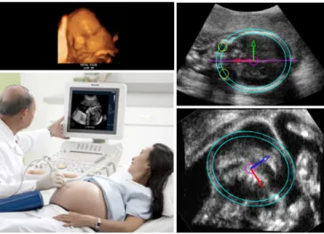
fe-Fig. 1.A near real time alignment of the fetal head during screening examinations to help navigate through the brain. The alignment is obtained by defining frame of reference based on the skull, the orbits of the eyes and the mid-sagittal plane
tal head alignment in 3D ultrasound scan (Figure 1). To be used in clinical routine, near real-time response is required (∼ 1s). Other potential applications include rapid initialization for deeper off-line analyses such as segmentation-based [3] or registration-based analyses [4, 5, 6].
Most papers in the literature tackle this alignment problem by registering the image onto a template or an image from an-other modality [4, 5, 6]. While these approaches may lead to more precise alignments, they require a pre-alignement step and their processes are often time consuming, which makes them unsuitable for clinical examination. Closely related to our work is Lu et al.’s contribution in [7] which aims at di-rectly finding specific heart planes in an 3D ultrasound based on the marginal learning space with probability boosting tree technique. However, the variability of the fetus position in utero yields specific challenges such as misleading contextual information (structures / organs that belong to the mother), clutter due to fetal skull and appearance change of brain struc-tures depending on their positions relatively to the probe. To
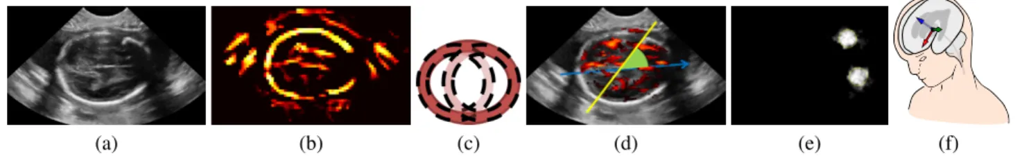
(a) (b) (c) (d) (e) (f)
Fig. 2. Workflow: (a) original image; (b) response P of a plate detector for the head detection; (c) approximation of the spheroidal shell by spherical shells for the head detection; (d) weigthed Hough transform on the response of a plate detector to detect the midsagittal plane; (e) probability map of the orbits’positions; (f) final frame of reference based on the head center, the eye position and the midsagittal plane.
cope with this challenging scenario, Feng et al. [8] combined both 3D and 2D datasets to detect the fetal face, thus requir-ing large and specific datasets. Moreover their method does not provide any alignment information.
In this paper, we propose a fast alignment method based on structures that are echogenic independently of the probe position: the skull, the midsagittal plane and the orbits of the eyes. The skull is detected and segmented using a shape model and a template deformation algorithm (Section 2). An initial anatomical frame of reference can thus be defined. Then, the detection of both midsagittal plane and orbits of the eyes allows to remove orientation ambiguities and even-tually to refine this frame of reference (Section 3). Detection algorithms are based on weighted Hough transform (for the midsagittal plane) and a random forest classifier that com-bines geometric information with image features (for the orbits). Experiments and results are detailed in Section 4.
2. SHAPE-BASED FETAL HEAD SEGMENTATION Robust segmentation of the fetal head needs the use of a shape model to cope with the presence of clutter, strong shadows and missing parts due to field of view variations. An ellip-soidal shell model is thus used to detect the fetal head (2.1). A precise segmentation is then obtained using this model as a deformable template (2.2).
2.1. Detection
Ultrasound images are prone to speckle, shadows and clutters and their intensity distributions are user dependent. Neverthe-less, the echo signal of the fetal skull has a plate-like structure whose size remains stable across subjects and acquisitions (2.5mm). Our detection is thus based on the response P to a plate detector [9] at a fixed scale (Figure 2.b).
We assume that the fetal head shape can be approximated by an ellipsoid. While a large number of methods exist to detect ellipsis in 2D (e.g. Hough-like transform, ML-based ellipse fitting [10]), most of them either break down in 3D or are not adapted to our problem due to computational time limitations. They either lack tolerance to noise and outlying structures or the number of parameters to estimate is too large. Therefore, for speed and robustness, we use a template
match-ing approach with a template whose Fourier Transform has an analytic expression. We thus consider a prolate spheroidal shell E . For a fast implementation E is approximated by a couple of spherical shells of the same radius and width (Fig-ure 2.c). Thus the skull detection boils down to convolving the response map P with a spherical shell BRof radius R and
se-lecting the couple (x1, x2) that maximizes BR∗P(x1) + BR∗
P(x2) under the constraint (2R + kx1− x2k) ∈ [dmin, dmax].
The values of dmin and dmax are set according to the range
of head sizes (50-80 mm for 19-24 weeks). The segment [x1, x2] gives the principal direction and center of the prolate
spheroidal shell. Its main and secondary axes lengths are set to R + d/2 and R respectively. To account for the variability of the fetal head sizes, the analysis is performed at different scales R. This detection approach has proven robustness to missing skull regions and noisy data with outlying structures. 2.2. Head Segmentation
Precise segmentation of fetal skull was done using the previ-ously detected ellipsoidal shell E as a deformable template. We followed the framework described in [11]. The goal is to find a transformation ψ maximizing the gradient flux across the surface of the deformed ellipsoid shell ψ−1(E ). Let φ be the signed distance function to E . The segmentation energy E in [11] adapted to our problem becomes:
E(ψ) = − Z
H(φ ◦ ψ) ∆P dx + λR(ψ) , (1) where H is the Heaviside function and R(ψ) is a regulariza-tion term which prevents large deviaregulariza-tions from the original template. The transformation is modeled as ψ = L ◦ G where G is a global transformation (typically an affine transforms) and L is a non-rigid local deformation. L is expressed us-ing a displacement field u such that L = Id + (u ∗ Kσ).
Kσ is a Gaussian kernel that provides built-in smoothness.
This decomposition allows R to be pose-invariant and con-strains only the non-rigid deformation: R(ψ) = R(L) = R
ΩkL − Idk 2 = R
Ωku ∗ Kσk
2. Energy E was minimized,
with respect to the parameters of G and each component of the vector field u, through a steepest gradient descent. Few iter-ations are generally needed since the ellipsoidal shell already provides a rough skull estimation.
3. SKULL-BASED FRAME OF REFERENCE We now search for a frame of reference based on the skull, the orbits’ positions and the midsagittal plane (Figure 2.f). From the mass center and the principal direction of the seg-mented skull we recover the center of the frame of reference and a sensible estimate of the anteroposterior axis. The medi-olateral axis is then computed based on the midsagittal plane detection (Section 3.1). Finally, orientation ambiguities are removed by determining the neck direction (Section 3.2) and the position of eyes’ orbits (Section 3.3).
3.1. Midsagittal plane detection
The midsagittal plane is echogenic and rather stable across scans. Its detection is also based on the response to the plate detector proposed in [9] but at a different scale (1mm). Since the proximal and distal hemispheres have different signals, symmetry based methods such as [12] do not apply. As the anteroposterior axis and the head center are known, detecting the midsagittal plane boils down to estimating only the plane rotation angle (Figure 2.d). This angle is estimated using a weighted Hough transform on the response map P. To favor correctly oriented plates, P is weighted at each voxel x by |h −cx→
k−cxk→ ∧ v, nxi| where c is the head center, v is a unit vector
of the anteroposterior axis and nxis the plate normal in x.
3.2. Neck orientation detection
Finally the orientation ambiguity is removed by detecting the neck along the longitudinal axis. Assuming that relatively low gradient is found in the neck region, we evaluate on the skull surface S the absolute flow of gradient in the direction of the longitudinal axis. Let u be a unit vector of the longitudinal axis. Vector u points toward the neck if and only if:
Z x∈Su+ |h∇I(x), ui|dµ < Z x∈S−S+u |h∇I(x), ui|dµ where S+ u = {x ∈ S : h −→
cx, ui > 0}. This simple criterion proves to ben robust across all our database.
3.3. Orbits detection
At this point, we lack only the orientation of the anteropos-terior axis. To find it, we detect the orbits’ positions with a random forest [13, 14]. We further use this detection to re-fine this axis estimation. We train a random forest classifier to predict, for each voxel x lying within a certain distance to the skull (5mm), the probability of belonging to an orbit (Fig-ure 2.e). This random forest combines geometric information with image features.
At a voxel x, features encoding geometric information include signed distance to the skull as well as the different angles between−cx and the three main axes (anteroposterior,→
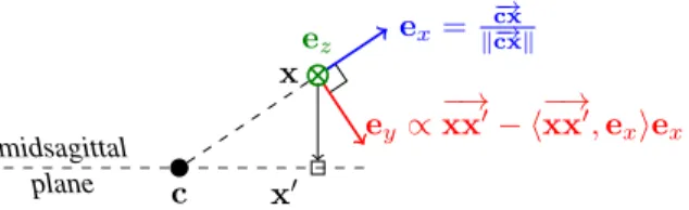
midsagittal plane c x x0 ex= −→ cx k−cxk→ ey∝ −→ xx0− h−→xx0, exiex ez
Fig. 3.Local orthonormal basis (ex, ey, ez) robust to the head
ori-entation to define random offsets. c: head center; x: voxel position; x0projection of x on the midsagittal plane
longitudinal or mediolateral).
As eyes’orbits appear in the scans as black balls surrounded by white structures, the image features, at a given scale (5mm), are differences of Laplacians between two voxels displaced by a random offset. To ensure robustness against fetal head position variability, random offsets are defined in a local basis (ex, ey, ez) (Figure 3).
Decision stumps are used as weak classifiers and the impurity criterion is the Gini index [13, 14]. The forest is composed of 5 trees with a maximum tree depth d = 10 and a minimal node size n = 100.
The position of the orbits relative to brain structures is more stable across different subjects than the main axis of the skull. Thus, we further consider as the anteroposterior axis the axis lying in the midsagittal plane defined by the head center c and the middle of the orbits’ centers (Figure 2.f).
4. EXPERIMENTS AND RESULTS
The validation of our method was performed on a dataset composed of 78 3D ultrasound volumes of fetal heads. The gestational age ranged between 19 and 24 weeks. Two experi-ments were carried out to assess our alignment method. First, since it relies on the orbits’ positions, we assessed their detec-tions by measuring the distance between the true and detected orbits’ centers (Section 4.1). Then, since screening exams at the considered fetal ages require measurements and visual as-sessments in three specific anatomical planes [1] (transthala-mic, transcerebellar and transventricular), we computed the variability of these planes’ coordinates in the detected frame of reference (Section 4.2).
The validation was done with a 2-fold cross-validation (50% training, 50% testing). The complete frame of refer-ence computation process took less than a second per image with a C++ CPU-based implementation (3.0 GHz quad-core, 8 GB RAM).
4.1. Eyes detection validation
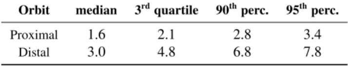
Detection errors in terms of distances between the true and the predicted centers are summed up in Table 1. The median error was 1.6 mm and 3.0 mm for the proximal orbit and the distal orbit respectively. The ultrasound clutter generated by
the skull explains the asymmetry of the results. Note that in our dataset, the order of magnitude of the orbits’ radii was 5mm.
Table 1. Detection error of the proximal and distal orbits’centers. Distances are indicated in mm.
Orbit median 3rdquartile 90thperc. 95thperc.
Proximal 1.6 2.1 2.8 3.4
Distal 3.0 4.8 6.8 7.8
4.2. Referential validation based on anatomical planes As the variance of a plane position and orientation is difficult to interpret, we quantified the planes’ coordinates variability as follows. We first computed the mean plane coordinates for the training set. In other words, we computated three Karcher means in R × S2. Then, for a given anatomical plane, the computed error was the maximal distance inside the skull be-tween the ground truth plane and the plane estimated by the mean coordinates. The errors are summarized in Table 2. Re-lying only on the skull, the midsagittal plane and the orbits of the eyes, our algorithm obtained robust and precise alignment of the fetal head in less than a second.
Table 2. Maximal error distance (in mm) within the head for the transcerebelar (TC), transthalamic (TT) and transventricular plane (TV).
Plane median 3rdquartile 90thperc. 95thperc.
TC 5.8 7.6 9.5 11.0
TT 5.1 6.9 8.8 10.8
TV 5.3 7.0 8.6 10.1
5. CONCLUSION
This paper presented a fast and fully automatic method to de-tect and align fetal heads in 3D ultrasound. The alignment is done by finding a frame of reference based on the anatomy. To be fast (∼s) and robust, our method relies on simple struc-tures whose signals remain stable across subjects and acqui-sitions: the skull, the midsagittal plane and the orbits of the eyes. The method proves to be fast and accurate on a dataset composed of 78 3D ultrasound volumes, which makes it com-patible with clinical routine. It could also be used as an initial-ization for deeper off-line analyses such as registration based analyses [4, 5, 6].
6. REFERENCES
[1] G. Malinger et al., “Sonographic examination of the fe-tal central nervous system: guidelines for performing the basic examination and the fetal neurosonogram.,” Ultrasound Obstet Gynecol, vol. 29, pp. 109–16, 2007. [2] World Health Organization, “Training in diagnostic
ul-trasound: Essentials, practice, and standards.,” Tech. Rep., WHO Geneva, 1998.
[3] J.A. Noble and D. Boukerroui, “Ultrasound image seg-mentation: A survey,” IEEE TMI, vol. 25, no. 8, pp. 987–10, 2006.
[4] A. Roche et al., “Rigid registration of 3-D ultrasound with MR images: a new approach combining intensity and gradient information,” IEEE TMI, vol. 20, no. 10, pp. 1038–49, 2001.
[5] M. Kuklisova-Murgasova et al., “Registration of 3D Fe-tal Brain US and MRI,” in MICCAI. 2012, vol. 7511 of LNCS, pp. 667–74, Springer.
[6] W. Wein et al., “Automatic CT-ultrasound registration for diagnostic imaging and image-guided intervention,” Medical image analysis, vol. 12, no. 5, pp. 577, 2008. [7] X. Lu et al., “AutoMPR: Automatic detection of
stan-dard planes in 3D echocardiography,” in ISBI. IEEE, 2008, pp. 1279–82.
[8] S. Feng et al., “Automatic fetal face detection from ul-trasound volumes via learning 3d and 2d information,” in CVPR. IEEE, 2009, pp. 2488–95.
[9] K. Mosaliganti et al., “Anisotropic plate diffusion filter-ing for detection of cell membranes in 3D microscopy images,” in ISBI. 2010, pp. 588–91, IEEE.
[10] Z.L. Szpak et al., “Guaranteed ellipse fitting with the sampson distance,” in ECCV, 2012, vol. 7576, pp. 87– 100.
[11] B. Mory et al., “Real-Time 3D Image Segmentation by User-Constrained Template Deformation,” in MICCAI, vol. 7510 of LNCS, pp. 561–68. Springer, 2012. [12] A.V. Tuzikov et al., “Brain symmetry plane computation
in MR images using inertia axes and optimization,” in Pattern Recognition. IEEE, 2002, vol. 1, pp. 516–19. [13] L. Breiman, “Random forests,” Machine learning, vol.
45, no. 1, pp. 5–32, 2001.
[14] A. Criminisi et al., “Decision forests for classification, regression, density estimation, manifold learning and semi-supervised learning,” Tech. Rep., Microsoft Re-search, 2011.