HAL Id: tel-01816985
https://tel.archives-ouvertes.fr/tel-01816985
Submitted on 15 Jun 2018HAL is a multi-disciplinary open access archive for the deposit and dissemination of sci-entific research documents, whether they are pub-lished or not. The documents may come from teaching and research institutions in France or abroad, or from public or private research centers.
L’archive ouverte pluridisciplinaire HAL, est destinée au dépôt et à la diffusion de documents scientifiques de niveau recherche, publiés ou non, émanant des établissements d’enseignement et de recherche français ou étrangers, des laboratoires publics ou privés.
Determination and Control System ground tests
Irina Gavrilovich
To cite this version:
Irina Gavrilovich. Development of a robotic system for CubeSat Attitude Determination and Control System ground tests. Automatic. Université Montpellier, 2016. English. �NNT : 2016MONTT329�. �tel-01816985�
Délivré par Université de Montpellier
Préparée au sein de l’école doctorale
Information, Structures, Systèmes (I2S)
Et de l’unité de recherche
Laboratoire d’Informatique, de Robotique et de
Microélectronique de Montpellier (LIRMM)
Spécialité : SYAM
Présentée par Irina GAVRILOVICH
Soutenue le 14 Décembre 2016 devant le jury composé de
Laurent Dusseau Professeur UM, Centre Spatial Universitaire Président François Pierrot DR CNRS LIRMM Directeur Sébastien Krut CR CNRS LIRMM Encadrant Marc Gouttefarde CR CNRS LIRMM Encadrant Gabriel Abba Professeur Université de Lorraine Rapporteur Paolo Tortora Assoc. Prof. Université de Bologne Rapporteur Sabrina Corpino Assist. Prof Ecole Polytechnique de Turin Examinateur
DEVELOPMENT OF A ROBOTIC SYSTEM
FOR CUBESAT ATTITUDE
DETERMINATION AND CONTROL
SYSTEM GROUND TESTS
[Tapez une citation prise dans le document ou la synthèse d'un passage intéressant. Vous pouvez placer la zone de texte n'importe où dans le document. Utilisez l'onglet Outils de zone de texte pour modifier la mise en forme de la zone de texte de la citation.]
RESUME
Après le lancement du premier satellite artificiel en 1957, l'évolution de diverses technologies a favorisé la miniaturisation des satellites. En 1999, le développement des nano-satellites modulaires appelés CubeSats, qui ont la forme d'un cube d'un décimètre de côté et une masse de 1 kg à 10 kg, a été initié par un effort commun de l'Université polytechnique de Californie et de l'Université de Stanford. Depuis lors, grâce à l’utilisation de composants électroniques standards à faible coût, les CubeSats se sont largement répandus.
Au cours des dernières années, le nombre de CubeSats lancés a régulièrement augmenté, mais moins de la moitié des missions ont atteint leurs objectifs. L'analyse des défaillances des CubeSats montre que la cause la plus évidente est le manque d’essais adéquats des composants du système ou du système au complet. Parmi les tâches particulièrement difficiles, on compte les essais « hardware-in-the-loop » (HIL) du système de contrôle d'attitude et d'orbite (SCAO) d’un CubeSat. Un système dédié à ces essais doit permettre des simulations fiables de l'environnement spatial et des mouvements réalistes des CubeSats. La façon la plus appropriée d’obtenir de telles conditions d’essai repose sur l’utilisation d’un coussin d'air. Toutefois, les mouvements du satellite sont alors contraints par les limites géométriques, qui sont inhérentes aux coussins d'air. De plus, après 15 années de développements de CubeSats, la liste des systèmes proposés pour tester leur SCAO reste très limitée.
Aussi, cette thèse est consacrée à l’étude et à la conception d’un système robotique innovant pour des essais HIL du SCAO d’un CubeSat. La nouveauté principale du système d'essai proposé est l’usage de quatre coussins d'air au lieu d'un seul et l’emploi d’un robot manipulateur. Ce système doit permettre des mouvements non contraints du CubeSat. Outre la conception du système d'essai, cette thèse porte sur les questions liées: (i) à la détermination de l'orientation d’un CubeSat au moyen de mesures sans contact; (ii) au comportement de l’assemblage des coussins d'air; (iii) à l'équilibrage des masses du système. Afin de vérifier la faisabilité de la conception proposée, un prototype du système d'essai a été développé et testé. Plusieurs modifications destinées à en simplifier la structure et à réduire le temps de fabrication ont été effectuées. Un robot Adept Viper s650 est notamment utilisé à la place d'un mécanisme sphérique spécifiquement conçu. Une stratégie de commande est proposée dans le but d’assurer un mouvement adéquat du robot qui doit suivre les rotations du CubeSat. Finalement, les résultats obtenus sont présentés et une évaluation globale du système d'essai est discutée.
ABSTRACT
After the launch of the first artificial Earth satellite in 1957, the evolution of various technologies has fostered the miniaturization of satellites. In 1999, the development of standardized modular satellites with masses limited to a few kilograms, called CubeSats, was initiated by a joint effort of California Polytechnic State University and Stanford University. Since then, CubeSats became a widespread and significant trend, due to a number of available off-the-shelf low cost components.
In last years, the number of launched CubeSats constantly grows, but less than half of all CubeSat missions achieved their goals (either partly or completely). The analysis of these failures shows that the most evident cause is a lack of proper component-level and system-level CubeSat testing. An especially challenging task is Hardware-In-the-Loop (HIL) tests of the Attitude Determination and Control System (ADCS). A system devoted to these tests shall offer reliable simulations of the space environment and allow realistic CubeSat motions. The most relevant approach to provide a satellite with such test conditions consists in using air bearing platforms. However, the possible satellite motions are strictly constrained because of geometrical limitations, which are inherent in the air bearing platforms. Despite 15 years of CubeSat history, the list of the air bearing platforms suitable for CubeSat ADCS test is very limited.
This thesis is devoted to the design and development of an air bearing testbed for CubeSat ADCS HIL testing. The main novelty of the proposed testbed design consists in using four air bearings instead of one and in utilizing a robotic arm, which allows potentially unconstrained CubeSat motions. Besides the testbed design principle, this thesis deals with the related issues of the determination of the CubeSat orientation by means of contactless measurements, and of the behavior of the air bearings, as well as with the need of a mass balancing method.
In order to verify the feasibility of the proposed design, a prototype of the testbed is developed and tested. Several modifications aimed at simplifying the structure and at shortening the fabrication timeline have been made. For this reason, the Adept Viper s650 robot is involved in place of a custom-designed 4DoF robotic arm. A control strategy is proposed in order to provide the robot with a proper motion to follow the CubeSat orientation. Finally, the obtained results are presented and the overall assessment of the proposed testbed is put into perspective.
ACKNOWLEDGEMENTS
First and foremost I would like to acknowledge my thesis director, Prof. François Pierrot, who accepted me as a Ph.D student at the LIRMM and has believed in my research. I would like to express my sincere gratitude to my thesis advisors, Sébastien Krut and Marc Gouttefarde, for they continuous support and guidance during these 3 years. Sébastien was the first person who welcomed me at the LIRMM and since then he has always provided me with encouragement and valuable advices whenever it was needed. I am very grateful to him for knowledge he has shared with me and all time he has spent to facilitate my habituation to the new domain. I appreciate all his contributions of energy, ideas and funding to make my research productive. Besides that he has helped me identify my professional strengths and accept them. I would like to thank Marc for his assistant with all my writings and his patience to correct them. I dare to believe that all his efforts to improve my writing skills were not in vain. They both, Sébastien and Marc, have taught me, equally consciously and unconsciously, how good research is done.
My research would not have been possible without support of the Montpellier-Nîmes University Space Center (CSU) and funding from the Van Allen Foundation. I wish to thank these organizations and personally Prof. Laurent Dusseau and Prof. Frédéric Saigné for giving me the invaluable opportunity to fulfill myself as a researcher, to present results of my work on several conferences and to write this thesis.
I would like to thank my colleagues from the Robotics Department for their readiness to help and to share their experience. Especially, I am grateful to Samah Shayya for his short in time, but very informative introduction to the Simulink Real-Time and Speedgoat target, and to Alonso Sanches who has aided me deal with the Viper robot and provided his C++ code that saved me a good half-year of work.
Let me also mention my friends who have been responsible for the entertainment aspects of my life during these years: Nastya, Artem, Andrey, Roman, Viyas. I appreciate their support, advices and all wonderful moments we have spent together, and I hope our friendship will last long despite distances and boarders.
I would like to express my deepest gratitude to my family that was the most supportive and motivating team I could ever imagine. I warmly thank my mom who bravely let me go in my big journey abroad and has always selflessly supported me in all my pursuits. And I especially thank my beloved husband who has always been on my side during these years. He has encouraged me when I needed it, he has inspired me when I ran out of new ideas, and he has never let me give up. More than I can express I am grateful to him for his faith in me and my intellect, unbelievable patience and endless love.
Lastly, I would like to thank everyone who has aided me on my long way to the Ph.D degree, those who has assisted to make my experiment happen, who has helped me deal with administrative and bureaucratic issues and those who has simply been around to cheer me up, and my cat that has comforted me with purring at the most tense moments of these three years.
CONTENTS RESUME ... 1 ABSTRACT ... 3 ACKNOWLEDGEMENTS ... 5 CONTENTS ... 1 LIST OF FIGURES ... 4 LIST OF TABLES... 7 ACRONYMS ... 8 INTRODUCTION ... 9
CHAPTER 1.CUBESAT TESTBED STATE OF THE ART ... 13
1.1 Introduction ... 13
1.2 CubeSats in brief ... 14
1.2.1 What is a CubeSat? ... 14
1.2.2 Success and failure ... 16
1.3 Overview of Attitude Determination and Control System (ADCS)... 19
1.3.1 Sensors ... 21
1.3.2 Actuators ... 22
1.3.3 Specificities of CubeSat ADCS ... 23
1.4 CubeSat ground tests philosophy ... 23
1.4.1 Environmental tests ... 24
1.4.2 Electrical tests ... 25
1.4.3 Functional tests ... 26
1.4.4 CubeSat testing scenario ... 26
1.5 ADCS HIL test facilities ... 27
1.5.1 Sun and starry sky simulators ... 27
1.5.2 Helmholtz cage ... 29
1.5.3 Overview of low-torque environment simulations ... 29
1.5.4 Air bearing platforms... 31
1.5.4.1 Planar systems ... 32
1.5.4.2 Rotational systems ... 34
1.5.4.3 Combination systems ... 37
1.6 Air bearing platforms for CubeSat ADCS tests ... 38
1.7 Technical requirements for the CubeSat ADCS testbed with improved performance ... 42
1.7.1 Perturbations caused by space environment ... 42
1.7.1.1 Gravity gradient torque ... 43
1.7.1.2 Aerodynamic torques ... 45
1.7.1.3 Solar pressure torque ... 46
1.7.1.4 Magnetic torques ... 46
1.8 Conclusion ... 49
CHAPTER 2.TESTBED CONCEPT AND PROTOTYPE ... 51
2.1 Concept ... 51
2.1.1 Dynamic compensation of MoI ... 51
2.1.1.1 1 DoF experimental setup ... 52
2.1.1.2 Experiment ... 53
2.1.2 Air-levitated whole sphere... 55
2.1.3 AirBall ... 57
2.2 Detailed AirBall design ... 58
2.2.1 Inner and Outer Spheres ... 58
2.2.2 CubeSat fastening and adjustment mechanism ... 60
2.2.3 Robotic Gimbal ... 61
2.2.4 Measurement system ... 64
2.2.5 Discussions on the design ... 65
2.3 AirBall prototype and employed components ... 66
2.3.1 Configuration ... 66
2.3.2 Air bearing Spheres with CubeSat mock-up... 67
2.3.3 Adept Viper s650 ... 70
2.3.3.1 Position for the External Sphere CoR in the work envelope ... 71
2.3.3.2 Inverse kinematics problem ... 72
2.3.4 Summary ... 73
2.4 Conclusion ... 75
CHAPTER 3.AIRBALL MODELING ... 77
3.1 Introduction ... 77
3.2 Air bearing Spheres behavior study ... 77
3.2.1 Assumptions and modelling ... 78
3.2.2 Mounting with a spring ... 80
3.2.3 Discussion on the simulation results ... 81
3.3 Determination of the CubeSat orientation ... 83
3.3.1 Approach with redundant measurements ... 84
3.3.2 Approach based on small angles approximation ... 86
3.3.3 Discussion on the simulation results ... 88
3.4 Mass balancing technique ... 89
3.4.1 Kinematics and dynamics ... 90
3.4.2 Dynamic parameters identification ... 91
3.4.3 Iterative mass balancing ... 93
3.4.4 Discussion on the simulation results ... 94
3.5 Conclusion ... 98
CHAPTER 4.AIRBALL EXPERIMENT ... 99
4.1 AirBall hardware ... 99
4.2 Robot Motion Control ... 101
4.2.2 Control scheme ... 103
4.2.3 Pose planning ... 104
4.3 Residual perturbations ... 105
4.3.1 Estimating perturbations ... 106
4.3.2 Experiment planning ... 107
4.4 Experimentation results and discussions ... 108
4.4.1 Friction torque in the AirBall testbed prototype ... 108
4.4.2 AirBall testbed prototype functional tests ... 110
4.5 Conclusion ... 112
CONCLUSION AND PERSPECTIVES ... 113
BIBLIOGRAPHY ... 115
LIST OF FIGURES
Figure 1.2-1 DTUsat-1 (Technical University of Denmark), ... 14
Figure 1.2-2 The 3U CubeSat O/OREOS is being inserted into a P-POD. ... 15
Figure 1.2-3 Number of CubeSat missions per year, considering presence of ADCS ... 16
Figure 1.2-4 CubeSat mission status for 2003-1015 years [2] ... 17
Figure 1.2-5 CubeSat Mission Failures for 2000-2012 years [4] ... 17
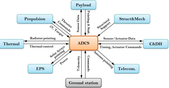
Figure 1.3-1 ADCS functional relationships ... 20
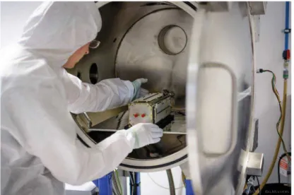
Figure 1.4-1 LituanicaSAT-2 is being installed in the thermal vacuum chamber ... 25
Figure 1.5-1 Optical head for starry sky simulation with the star tracker camera mounted [47] (left); Scheme of the starry sky simulating facility with the LCD monitor and collimating optics [44] (right) ... 28
Figure 1.5-2 Helmholtz cages designed at Delft University of technology [53] (left) and at UC Berkeley [54] (right) ... 29
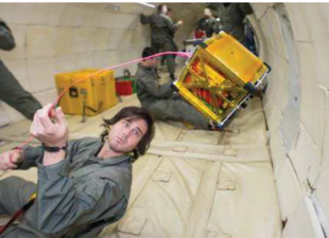
Figure 1.5-3 KnightCube (University of Central Florida) ADCS testing in microgravity conditions during the parabolic flight ... 31
Figure 1.5-4 CubeSat mockup with ADCS components suspended on a string inside Helmholtz coils [64] ... 31
Figure 1.5-5 Five satellite maneuvers, SPHERES projects [66] ... 32
Figure 1.5-6 Two autonomous robots manipulate a zig-zag flexible element on a air bearing table [73] ... 33
Figure 1.5-7 Tabletop, umbrella and dumbbell system configurations ... 34
Figure 1.5-8 NASA Ames Research Center tabletop air bearing platform, dated 1959 (left) and Marshall Space Flight Center umbrella platform, dated 1960 (right) [56] ... 35
Figure 1.5-9 A three-axis air bearing based platform for small satellites [84] ... 36
Figure 1.5-10 Dumbbell air bearing testbed for Army Lightweight ExoAtmospheric Projectile [81] ... 36
Figure 1.5-11 The synchronized rotation experiment setup and the interior the air-levitated sphere [86] ... 37
Figure 1.5-12 Rensselaer Polytechnic Institute 6 DoF platform [87] ... 37
Figure 1.6-1 The NanoSat Air Bearing [93] ... 39
Figure 1.6-2 SX-025 nanosatellite test facility [46] ... 40
Figure 1.6-3 Air bearing testbed with ExoplanetSat simulator [94] ... 40
Figure 1.6-4 Air bearing simulator at York University [57] ... 41
Figure 1.6-5 CubeTAS system overview (left) and hemisphere interior (right) [56] .... 42
Figure 1.7-1 Gravity gradient ... 43
Figure 1.7-2 JB2008 mean atmosphere density with altitude for low, moderate, high long- and short-term solar and geomagnetic activity (from [97]) ... 46
Figure 2.1-1 3U CubeSat on gimbal suspension ... 51
Figure 2.1-2 Concept of the 1 DoF planar platform with the MoI compensation ... 52
Figure 2.1-4 Control scheme for the dynamic MoI compensation on the 1 DoF
experimental setup ... 54
Figure 2.1-5 Experimental setup scheme ... 55
Figure 2.1-6 EyasSat's sphere for ADCS simulations ... 56
Figure 2.1-7 An air-levitated sphere and a spherical structure of the same diameter formed by several air bearings ... 57
Figure 2.2-1 Orifice vs. porous media air bearings [105] ... 58
Figure 2.2-2 a – regular tetrahedron inscribed in a sphere; b and c - same sphere with 1U CubeSat- and 3U CubeSat-size cuboids, correspondingly ... 59
Figure 2.2-3 Inner and Outer Spheres ... 59
Figure 2.2-4 Fastening and adjustment mechanism ... 60
Figure 2.2-5 Geometrical model of the robotic gimbal ... 61
Figure 2.2-6 Inverse kinematics algorithm for the 4 DoF robotic gimbal ... 64
Figure 2.2-7 Air bearing with a micro distance sensor (only one shown) ... 65
Figure 2.2-8 AirBall testbed ... 66
Figure 2.3-1 Chart flow of the AirBall prototype development ... 67
Figure 2.3-2 Correct position of an active part of the air bearing (left) and its misalignment due to distance from CoR (center) and non-concentricity (right) ... 68
Figure 2.3-3 Sphere constrained by the air bearing linkages ... 69
Figure 2.3-4 The AirBall prototype ... 69
Figure 2.3-5 Viper s650 anatomy and work envelope [118] ... 70
Figure 2.3-6 Selected point on the sphere with its center at the desired CoR is examined to find the inverse kinematics solutions for the corresponring end effector posture ... 71
Figure 2.3-7 Attainable area (black dots) of the sphere ... 71
Figure 2.3-8 6 DoF manipulator geometry described by the OPW-parameters [119] and table of those for the Adept Viper s650 ... 72
Figure 2.3-9 The AirBall prototype comprising the Inner and Outer Spheres with 4 air bearings, 3 laser sensors and 1U CubeSat mock-up, and the Adept Viper s650 ... 74
Figure 3.2-1 Fly height – lift force curve for the 40mm porous carbon air bearing. Local slope represents the local stiffness. ... 77
Figure 3.2-2 Free body diagram of the Inner Sphere ... 79
Figure 3.2-3 Free body diagram of the air bearing active element with a spring ... 80
Figure 3.2-4 Lift force, fly height and Inner Sphere CoM trajectory diagrams for the system with rigidly fixed air bearings. Sphere clearance 5 µm ... 81
Figure 3.2-5 Lift force, fly height and Inner Sphere CoM trajectory diagrams for the system where one air bearing is adjusted by a spring. Sphere clearance 5 µm ... 82
Figure 3.2-6 Magnitude of the Inner Sphere CoM fluctuations: left – all air bearings are rigidly fixed; right - one air bearing is adjusted by a spring. Sphere clearance 5…100 µm .. 83
Figure 3.3-1 Frames involved in the tracking process.. ... 84
Figure 3.3-2 Geometrical model of the passive part of the air bearing and the measurement rays ... 85
Figure 3.3-3 Orientation of the reference shape ... 867
Figure 3.3-4 The simulation results of the CubeSat orientation determination for the approach with the small angles approximation. 3DoF rotation of the Inner Sphere with respect to the Outer Sphere ... 89
Figure 3.4-1 Frames involved in the identification process ... 91
Figure 3.4-2 Simulation scheme of the identification of dynamic parameters ... 95
Figure 4.1-1 Assembled AirBall prototype ... 99
Figure 4.1-2 Air bearing close up ... 100
Figure 4.1-3 Fine tuning of the Outer Sphere. Nominal radius 105 mm ... 100
Figure 4.2-1 Complete view of the prototype: AirBall and Viper s650 ... 102
Figure 4.2-2 Robot control architecture ... 103
Figure 4.2-3 Steering control scheme ... 104
Figure 4.2-4 Coordinate frames and transformations ... 104
Figure 4.4-1 Numbering of the sensors arranged on the AirBall ... 108
Figure 4.4-2 Measurements obtained from the sensors during the Inner Sphere oscillation ... 109
Figure 4.4-3 Open-loop test, camera 1 ... 110
Figure 4.4-4 Open-loop test, camera 2 ... 110
Figure 4.4-5 Closed-loop test. CubeSat mockup is pushed counterclockwise (a) and clockwise (b) ... 111
LIST OF TABLES
Table 1 Reaction wheels ... 38
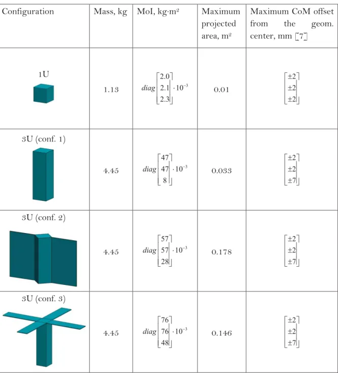
Table 2 CubeSat configurations and their physical parameters for the perturbation torques calculation ... 44
Table 3 Estimated disturbance torques for different CubeSat configurations . 47 Table 4 Testbed functional requirements ... 48
Table 5 Denavit-Hartenberg parameters for the robotic gimbal... 61
Table 6 Spherical porous media air bearings ... 68
Table 7 Adept Viper s650 specification ... 70
Table 8 Initial conditions ... 96
Table 9 Scaling coefficients ... 96
Table 10 Comparison of the predefined and identified values ... 96
ACRONYMS
ADCS Attitude Determination and Control System C&DH Command and Data Handling
CAD Computer-aided design
CoM Center of mass
CoR Center of rotation
COTS Commercial-off-the-shelf DAC Data acquisition card DoF Degree of freedom EPS Electrical Power System EVA Extra-vehicular activity FOV Field of view
GC Geometrical center
GNC Guidance, Navigation and Control GPS Global Positioning System
HIL Hardware-in-the-loop IMU Inertial measurement unit ISS International Space Station
LEO Low Earth orbit
LS Least Square
MEMS Micro-Electro-Mechanical System
OPW Ortho-parallel manipulator with spherical wrist P-POD Poly-Picosatellite Orbital Deployer
INTRODUCTION
The history of space exploration started in 1957 with the launch of the first artificial Earth satellite. This event opened the door for thousands of space missions to be launched, including inhabited space stations, manned and unmanned Moon expeditions, and deep space exploration. The success of many of these missions significantly impacted technology and science. Years later, and despite the progress of manned missions, satellites are in high demand in numerous domains, such as telecommunications, technological, educational and scientific projects, Earth, sun-orbiting planet and asteroid observations, and defense programs.
Satellite technology has significantly evolved since the 1960s. These technological changes have affected not only the performance capabilities of satellites, but also their size. Thus, thanks to the minimization of electric and other components, and with masses similar to those of older satellites, modern satellites are able to perform a wider range of tasks. This is particularly true for spacecraft intended to operate at large distances from Earth, as illustrated by Mars exploration missions: Viking 11, the first spacecraft to successfully land on Mars in 1975, and Mars Science Laboratory (MSL)2, with the Curiosity rover, which landed in 2012, had similar fueled (3,527 kg and 3,893 kg) and lander (572 kg and 899 kg) masses. Besides a mobility system designed to exceed a total distance of at least 19 km, Curiosity contains 13 on-board instruments, which allow an incomparably wider range of investigations than was available with the Viking 1 lander. However, not only did the performance of the spacecraft increase, but their masses also decreased for the same range of function capabilities. This is illustrated by several satellites designed for Earth observation in the last 20 years. Spot 53 (3,030 kg, launched in 2002), RapidEye3 (150 kg, launched in 2008) and Flock3 (5 kg, launched in 2014) were intended for similar purposes, yet had dramatically different masses and – consequently – project cost structures.
The evolution of technology has thusly fostered the miniaturization of satellites. In 1999, the CubeSat program was started. CubeSats are standardized modular nanosatellites (with masses limited to few kilograms), which have to be built according to specifications guaranteeing their compatibility with deployment systems. Furthermore, commercial off-the-shelf components are widely used in CubeSat design. As a whole, CubeSat guidelines make for shorter development timelines and lower expenses. As a result, CubeSats have therefore become a popular bus for space missions. Every year, the number of CubeSat launches increases; their mission objectives become more and more sophisticated and ambitious. Hence, the first CubeSats, launched in 2003, were mainly devoted to amateur radio and technology demonstrations. Today, they increasingly complement deep space missions: In 2017, INSPIRE4 will demonstrate CubeSat functionality in deep space and, later on, MarCO5 will fly independently to the Mars orbit to perform telecommunication
1http://www.jpl.nasa.gov/missions/viking-1/ 2http://mars.jpl.nasa.gov/msl/ 3https://directory.eoportal.org 4http://www.jpl.nasa.gov/cubesat/missions/inspire.php 5http://www.jpl.nasa.gov/cubesat/missions/marco.php
tasks. The anticipated success of these CubeSat missions will usher the era of deep space nanosatellites, making the exploration of the Solar system faster and cheaper. Obviously, such missions require more sophisticated architecture of satellite subsystems.
The trend towards more complex CubeSats presents higher risks of failure. Indeed, the specific operational parameters of the space environment render spacecraft repair almost impossible. This is particularly true for small satellites, because repair costs usually vastly exceed total satellite production and launch costs. In the history of space flights, successful on-orbit repairs have been made only to inhabited orbital stations, the Solar Maximum Mission and the famous Hubble Space Telescope. It is therefore essential that potential satellite malfunctions be identified and fixed before their launch.
One of the most complex and sensitive subsystems of a satellite is the Attitude Determination and Control System (ADCS), which determines the satellite’s orientation and controls its stabilization, pointing and maneuvers.
Several techniques are used to perform ADCS component ground tests. However, testing the whole system is challenging because it requires simulating spatial conditions and effects, as well as satellite dynamics. Simulators were initially designed in the early 1960s (Smith, 1965). They allowed the placement of the satellite’s ADCS components on an air bearing table which eliminated friction. Precise mass balancing ensured minimized gravity torque effects; sensor signals were simulated electrically or optically. These systems were used mainly for control law studies and rarely for assembled hardware evaluations. Since then, the architecture of test platforms has not undergone significant changes. While other techniques to simulate low-torque environment were developed, the use of air-bearing platforms remains prevalent for the complete testing of satellite ADCS.
However advanced, the test systems developed for larger satellites are not adapted for small satellite testing – still less for CubeSat testing. The main issue is the unacceptable level of residual perturbations caused – mostly – by the respectively large mass and moments of inertia of the table. This thesis is devoted to the design and development of an experimental system suitable for CubeSat ADCS evaluation. Additionally, a task to extend the performance range of existent air bearing testbeds is proposed. To this end, a robotic gimbal is used to widen the rotational freedom of the CubeSat on the testbed. In spacecraft design, manipulators are used widely and for a variety of purposes. The most renowned examples are the manipulators used on the Space Shuttle and the International Space Station: Canadarm and Canadarm2, Dextre, the European Robotic Arm and the Remote Manipulator System. They were built to perform various tasks, such as moving cargo and equipment, assisting with station assembly and docking, and even providing assistance to astronauts working in space. The Canadarm was used in the repair missions mentioned above. However, examples of a robotic arm application for air bearing ADCS testbeds were not found in the literature.
This thesis is organized in four chapters:
Chapter 1 introduces the historical and statistical background of CubeSats. This information is necessary to understand the motivation for the thesis. Subsequently, an overview of the CubeSat subsystem is presented, with a focus on the ADCS. Further, an introduction to CubeSat ground testing is given. It is followed by a detailed State-of-the-Art review of test facilities for satellite ADCS, ranging from 1960’s CubeSat test platforms to
the most current ones. This review highlights the shortcomings and limitations of current test systems, and presents the motivation for the development of a new ADCS testbed for CubeSats. Finally, based on the calculations of the perturbations experienced by a CubeSat in the space environment, technical requirements for the testbed are formulated.
Chapter 2 proposes three approaches to extending the performance range of a CubeSat ADCS testbed and to satisfying the aforementioned requirements. All three approaches rely on the use of air bearings as a means to minimize friction, but the manner in which unconstrained rotation is provided to the CubeSat differs. One of these approaches is selected for implementation: It is based on a novel way to combine spherical air bearings with a robotic gimbal. This testbed concept, called AirBall, is presented, and the design of its prototype is described in details.
Chapter 3 introduces the numerical simulations required to verify the feasibility of the proposed testbed concept. First, the study of the behavior of the air bearing assembly is presented with related simulation results. Further, techniques required to determine CubeSat orientation and perform mass balancing are described. The results of the simulations illustrate the efficiency of those newly developed techniques.
Chapter 4 is devoted to experimentations with the AirBall prototype. Specifically, test objectives, experiment setup and results are presented. Additionally, the control strategy required to use the Viper s650 robot arm is examined.
In the Conclusion, an overall assessment of the proposed AirBall testbed is given and put into perspective. It includes concluding remarks about the prototype’s performance and perspectives for future work.
The main contributions of this thesis can be outlined as follows:
• The design and development of an experimental testbed with a robotic
gimbal for CubeSat ADCS testing. The AirBall testbed employs a novel
concept of the air bearing platform, whose essential part is a spherical assembly comprising four air bearings. CubeSats can conveniently be placed in the center of the sphere; the system provides it with unconstrained rotation.
• The assessment of an air bearing platform’s behavior, including the analysis of the relative platform and payload motions.
• The determination of CubeSat orientation using contactless indirect measurements. The system is capable of providing information about the angular position of a rotating rigid body via a minimum of three distance sensors.
• A mass balancing technique for CubeSat testbeds without any actuation means. Related algorithms are proposed and confirmed by the simulation results.
Chapter 1. C
UBESAT TESTBED STATE OF THE ART1.1 INTRODUCTION
Since CubeSat program has started in 1999, CubeSat-class nanosatellites became a widespread and significant trend. Due to low cost and a number of off-the-shelf components, the development of such satellites became common, especially among school and universities. Building a CubeSat takes less time than needed to design a nanosatellite from scratch. Hence, developers can focus on scientific payload integration and students can lead the project through all stages during their university years. Despite small sizes and standardized construction, CubeSats are useful to solve wide range of tasks in different fields of space exploration - communication, earth and near-earth space observation, scientific missions.
Despite a significant difference in size, CubeSats inherit their system architecture from previous generations of satellites. All systems required to ensure CubeSat functions are similar to those of large satellites, but their complexity and component selection are constrained by strict size and mass requirements. Besides these constrains, CubeSat developers are often limited by budget and timeline that results in wide usage of commercial-off-the-shelf (COTS) components with minimum or zero space heritage. Malfunction of one element in a system is enough to bring a whole satellite failure. In order to verify that components keep their functions under space environment and the CubeSat operates properly, ground tests shall be performed for every involved component and system.
The Attitude Determination and Control System (ADCS) is one of the most difficult systems to test. The ADCS verification requires dynamic simulations of the space environment and some freedom of the CubeSat motion. There are several techniques to permit satellite motion in a low-torque environment, i.e. an environment with minimized gravity and friction torques. Every technique has its own advantages and disadvantages, and the air bearing platform is the most widely used approach. Air bearing platforms for large satellites have been developed for more than 50 years. However, they cannot be adopted for CubeSat tests due to several distinctions.
This Chapter is devoted to the survey of the CubeSat ground test facilities and, particularly, air bearing testbeds. Section 1.2 gives an introduction into CubeSats, including a general overview of this class of nanosatellites, a statistical analysis of CubeSat missions and lessons to be learnt from the past 15 years of CubeSat development. Section 1.3 introduces the ADCS architecture, its essential components, and distinctive features of CubeSat ADCS. The prior to launch satellite verification philosophy is presented in Section 1.4 together with the typical strategy of the CubeSats tests. Section 1.5 is focused on the overview of satellite ground test facilities and, especially, existing air bearing platforms for ADCS dynamic tests. Section 1.6 is dedicated to the state of the art of the air bearing platforms suitable for CubeSats. The main goal of this thesis is stated in Section 1.7 together with the requirements to be fulfilled. In Section 1.8 the conclusion of the Chapter is given.
1.2 CUBESATS IN BRIEF 1.2.1 What is a CubeSat?
Almost fifty years after the beginning of the Space Age, the CubeSat standard was initiated as a response to the current principle of the satellites: “Smaller, Cheaper, Faster, Better” [1]. The concept of a nanosatellite with mass <1 kg and the size of a 10 cm cube was publicly proposed in 2000 as result of a cooperation between California Polytechnic State University (Cal Poly) and Stanford University. And shortly after, this concept evolved to the unified nanosatellite platform called CubeSat that consists of one (1U) or multiple (0.5U, 3U, etc.) standardized 100x100x113.5 mm cubic units with mass not exceeding 1.33kg per unit. The first CubeSats were successfully launched in June 2003, and in ten years their number has exceeded one hundred. By April 2016, there are 431 CubeSats-class missions designed in various institutions all over the world and launched, more of them are scheduled for the coming years [2].
Figure 1.2-1 DTUsat-1 (Technical University of Denmark), one of first CubeSats launched in June 2003 [3]
By the original definition, a CubeSat is compatible with the deployment container Poly-Picosatellite Orbital Deployer (POD), which is developed by Cal Poly and Stanford. P-POD provides a standardized launch interface and is able to carry a total of 3U. Several equivalent interfaces, designed by other organizations, are also dedicated to be compatible with the CubeSats [4]:
• Innovative Solutions in Space (ISIS): ISIPOD;
• Japan Aerospace Exploration Agency (JAXA): J-POD; • NASA: Nanosatellite Launch Adapter Systems (NLAS);
• University of Toronto Space Flight Laboratory (SFL): T-POD and X-POD; • U.S. Department of Defense: Space Shuttle Picosatellite Launcher (SSPL); • Astro- und Feinwerktechnik Adlershof GmbH: PicoSatellite Launcher (PSL). Additionally, the following systems shall be mentioned, as they allow deploying CubeSats from the International Space Station (ISS):
• JAXA: JEM Small Satellite Orbital Deployer (J-SSOD) [5]; • NanoRacks: NanoRacks CubeSat Deployer (NRCSD) [6].
These deployers vary in their internal dimensions and some other constrains. Thus, ISIPOD admits 3U CubeSats with mass up to 6 kg, while P-POD requires 3U to not exceed 4 kg. Some containers allow a custom design to accommodate up to 6U, or provide individual placement for 1U and 2U, that let CubeSat developers be more independent, when scheduling a launch. Despite these differences, the CubeSats shall meet common requirements given by the CubeSat Design Specification [7] that guarantees their compatibility.
Standardized launch containers and strict CubeSat mass limits lead to minimized launch and integration cost. The P-POD and its analogues allow CubeSats to be mounted on various launch vehicles and give great flexibility for seeking launch opportunity [8]. This makes the CubeSat and deployment container tandem an ideal secondary payload.
Figure 1.2-2 The 3U CubeSat O/OREOS is being inserted into a P-POD. Photo: NASA
In addition to featuring miniature dimensions and having standardized deployment systems, CubeSats are remarkable as a standard small-scale satellite platform. The platform (or bus) is the infrastructure of a satellite supporting different mission-oriented payloads. Using standard platforms, a customer does not have to develop the satellite from scratch and can focus on the desired experiment and payload. Comparing to a one-off, this approach to design spacecrafts reduces costs and improves operability. As for any other satellite, a CubeSat bus consists of several subsystems [9]:
• Command and Data Handling (C&DH) • Telecommunication System
• Electrical Power System (EPS) • Thermal Control
• Attitude Determination and Control System (ADCS) • Guidance, Navigation & Orbit Control (GNC) • Structure and mechanisms
• Propulsion
However, for several missions, some of the subsystems listed above are excessive and can be omitted. For example, propulsion system is a rare choice for CubeSats, because the latter generally stay on their initially reached orbit. But some CubeSats have thrusters on
board: ESTCube-1 was aimed at making an experiment with an electric solar wind sail [10]; Lunar IceCube (NASA), designed to fly to the Moon orbit in 2018, make use of a miniature electric ion engine [11]. Also, ADCS is missing on some CubeSats, whose missions do not require the attitude control (instead, having free rotation). In the following Sections, this aspect will be discussed in details. Other subsystems, even with significant performance degradation comparing to full-scale satellites, always have to be part of the CubeSat bus.
The wide choice of COST components for the mechanical structure and subsystems makes the CubeSat a great customized platform for educational and technological missions, which have to be completed in 1-2 years. Indeed, each subsystem can be assembled of the components available in number of specialized CubeSat shops [12]–[14]. Besides, CubeSats are able to perform quite complicated missions competing with larger satellites. Such missions require newly developed components and subsystems that imply more time and higher costs to build the satellite. However, the obvious advantages of the simplified integration and low launch cost attract more satellite developers every year to choose CubeSats.
1.2.2 Success and failure
The CubeSat features stated above, lead to the large popularity of these nanosatellites. As Figure 1.2-3 shows, the number of CubeSats dramatically increased in 2013 and still grows every year.
Thanks to accessibility of CubeSats, 34 countries performed their own space mission so far, and for 14 of them, it was the first satellite launch. More than 150 CubeSats have been developed by universities for educational, science, communication or technology demonstration purposes. Besides, 182 of 431 CubeSats are built by private organizations for commercial uses. The world’s largest constellation of Earth-imaging satellites, called the Flock and reckoned at 77 successfully launched CubeSats [15], [16], contributes a lot in these numbers. The other CubeSat missions belong to civil or military/defense government organizations [2], [17]. This statistics clearly indicates that CubeSats are highly demanded by different developers, from amateurs to governmental institutions, and can be used in a wide range of applications. It can be confidently asserted that, in the coming years CubeSats will continue to grow in number and their subsystems and missions are expected to be more intriguing and challenging.
However, not all CubeSat missions succeed. As shown in Figure 1.2-4, less than 50% of the launched satellites achieved their goals. The harmful factor, which strikes CubeSats massively and cannot be predicted or avoided by the developer, is a launch vehicle crash. As nanosatellites mainly launched in groups, one launch failure kills dozens of them. For 12 years of CubeSat development, almost 100 nanosatellites are lost because of only 4 launch failures.
Figure 1.2-4 CubeSat mission status for 2003-1015 years [2]
The examination of the reasons that lead to mission failures after the deployment shows distribution of the subsystem malfunctions (Figure 1.2-5) [4]. It is easily seen, that almost half of failed CubeSats have never been contacted after launch. There are many causes that possibly lead to this end, and, unluckily, they cannot be identified due to specificities of the space missions. However, they can be estimated based on the statistics (Figure 1.2-5) or analyzing the examples of the CubeSats, which were semi-functional after deployment and reanimated lately. The leading positions through the recognized failure reasons belong to communication and power malfunctions. Though, they are not always caused by Telecommunication subsystem and EPS, because statistics represents reasons of satellite failure, but not the actual causes.
The most critical stage of the CubeSat on-orbit operation is its separation from the deployment container. As CubeSats are usually regarded as secondary payloads, the tip-off rates imparted on a CubeSat upon separation is weakly overseen [18]. Providers of the deployment system do not declare maximum tip-off rates that CubeSats may acquire during the separation from the container. While according to the study of the CubeSat separation dynamics [19] the theoretical tip-off rate does not exceed 45 °/s, based on experience, a CubeSat might get spinning up to 100 °/s [20] and, exceptionally, even higher. Moreover, since many CubeSats have ADCS with an extremely limited efficiency, the unexpectedly high-speed tumbling can be critical for them. Accordingly, when a CubeSat didn’t succeed to recharge accumulator batteries or cannot properly communicate with a ground station, the possible cause is an incorrect satellite attitude due to the ADCS fault. Several examples well illustrate the significance of ADCS for the proper CubeSat on orbit operation and, therefore, for the CubeSat failure:
• SwissCube, the first Swiss satellite, launched in September 2009, acquired extremely high rotation around 200 °/s after separation that prevented from using its payload or trying to de-tumble by means of ADCS. It was decided to let SwissCube de-tumble “naturally”, and in 14 months the rotation slowed down to 80 °/s, then ADCS could accomplish the stabilization. While the planned SwissCube lifetime was 4 month, all satellite systems were still able to work. In February 2011, SwissCube was fully controlled and still stays operational so far [21].
• AAUSAT3, the third Danish student-built CubeSat, launched in February 2013, experienced a spin velocity of almost 540 °/s due to both the separation rate and an incorrect feedback sign of one of the magnetic coils in ADCS. Fortunately, this bug was identified and fixed in a good timing and AAUSAT3 managed to de-tumble itself. It successfully operated until October 2014. Developers noted that if AAUSAT3 had reached 650 °/s, it would have been impossible to recover it [22].
• SamSat-218, the Russian CubeSat developed by the Samara State Aerospace University, was launched in April 2016. At the moment (May 2016) SamSat-218 does not communicate with ground stations, while some radio enthusiasts report hearing fragments of Morse code from the CubeSat. According to the developer’s hypothesis, the high tip-off rate during the satellite deployment prevents SanSat-218 from successful communication with the ground [23], [24].
Indeed, ADCS is the system which ensures the safety of a CubeSat in the early stages of the on-orbit operation and supports its correct work later on. The statistics of CubeSats employing ADCS (Figure 1.2-3) shows that majority of launched missions carries on board ADCS components, but their complexity and performance vary widely: from a rough attitude measurement to a full-functional 3-axis control analogous to the systems used for larger satellites. Nonetheless, every year the proportion of nanosatellites with no attitude control declines, and the tendency of CubeSat missions leaves ADCS no option but to improve its performance. The current state of the art of ADCS technologies is given in the following section.
1.3 OVERVIEW OF ATTITUDE DETERMINATION AND CONTROL SYSTEM (ADCS)
Any satellite mission is designed according to the needs of the payload, which requires certain orientation at definite time. However, the payload is not designed to change satellite orientation and an Attitude Determination and Control System (ADCS) is provided for this purpose. ADCS is a subsystem, which determines the satellite attitude using sensors and provides attitude control using actuators.
Satellite attitude is defined by the relationship between axes of the satellite and some reference frame, and usually described by yaw, pitch and roll angles. Depending on the mission objectives and used sensors, different reference frames (or all of them) can be employed for attitude determination [25], [26]:
• International Celestial Reference System (ICRS) has its origin at the center of mass (CoM) of the solar system. The z axis is aligned to the Earth’s North Pole and the x axis with the vernal equinox. ICRS is the basis for fundamental measurements of the positions and motion of celestial bodies; it is used for interplanetary missions.
• Earth Centered Inertial (ECI) coordinate system has its origin at the geometric Earth center. The z axis is aligned to the Earth’s North Pole and the x axis points towards the vernal equinox. Satellite orientation with respect to the ECI can be determined from stellar observation.
• Earth Centered Earth Fixed (ECEF) coordinate system rotates with the Earth, so its z axis is aligned to the Earth’s North Pole and the x axis is pointed to the intersection between the prime meridian and the equator. Satellite orientation with respect to ECEF is required for ground communication tasks and for any Earth sensing mission.
• Orbit Fixed Coordinate System is fixed to the satellite body. Its z axis points directly away from Earth center (to nadir) and its x axis is tangent to the orbit trajectory. It is often used for Earth pointing satellites.
The ADCS is tightly coupled to other satellite subsystems and this makes it responsible for correct operation of the whole satellite (Figure 1.3-1). As it was mentioned in the previous section, number of malfunctions was caused by ADCS failures. For proper satellite operation, the ADCS has to perform the following tasks [25]:
• Provides satellite attitude knowledge;
• Provides rate stabilization and pointing for payload and other subsystems; • Provides rate and attitude control, and station keeping maneuvers;
Depending on the mission objectives, different control techniques can be implemented by means of ADCS [25], [27]–[29].
When there is no need to rotate the satellite quickly and change its pointing, passive control techniques are used. They take advantage of basic physical principles: The control forces are generated by means of interaction between a satellite and the space environment.
Figure 1.3-1 ADCS functional relationships
The gravity-gradient controlled satellites use the property of an elongated body in a gravity field to align its minimum inertia axis with the local vertical. Often a deployed boom is used to enlarge the inertia of two satellite axes and to accentuate the one, which it pointed to Earth’s center. This technique is very helpful for satellites in Low Earth Orbit (LEO) without yaw orientation requirements.
Other type of passive ADCS employs a permanent magnet to make the satellite aligned in the Earth’s magnetic field. This attitude control usually experiences some perturbations caused by variations of the Earth’s magnetic field, though this technique is more reliable for near-equatorial orbits where the magnetic field stays almost stable.
The passive control techniques have very limited accuracy and provide only two-axis stabilization, when they are not combined together or with other methods.
Spin stabilization can also be considered as a passive control technique, because it relies on the gyroscopic stability, so that the satellite angular momentum vector is almost fixed in inertial space. A spin-stabilized satellite (or spinner) is stable if it is spinning about the largest inertia axis. The higher the stored momentum is, the less sensitive to disturbances the satellite is. Thus, when a spinner has to be reoriented, extra torque is required because of the gyroscopic stiffness. Another disadvantage is that a spinner must be actively controlled if has any cause of energy dissipation on board and to periodically adjust its attitude and spin rate.
Three-axis control technique is the most developed approach to satellite attitude control. It allows 3-axes stabilization as well as stable, agile and accurate maneuvers. And these capabilities require both sensors and actuators that make active ADCS more complex and expensive comparing to passive one. There are two sub-types of three-axis control: (i) Momentum bias systems are similar to the spin stabilization, with an exception that it employs a wheel (with its spin axis normal to the orbit plane) to provide gyroscopic stiffness. This wheel is also used to control attitude by slightly changing its speed. (ii) Zero-momentum systems rely on the actuators which keep a satellite stable responding to disturbances and provide required maneuvers (satisfying both rate and pointing constrains).
The selected control technique must respond to the needs of satellite mission: 2- or 3-axis control, accuracy of stabilization and pointing, reorientation speed. The ADCS
hardware generally uses two types of components: sensors and actuators, whose classification and features are explained in the following sections.
1.3.1 Sensors
While actuators are not always included in the ADCS, as it was enlightened above, sensors are essential components of the ADCS. They ensure determination of the current satellite attitude with respect to the chosen coordinate system. The sensor technologies typically used for the satellite ADCS and their performance specifics are introduced below [9], [27]–[29].
Sun sensors measure two angles between their base and the direction to the sun. They range from detectors that find whether the Sun is in the field of view (FOV), to the fine instruments that can accurately determine its direction. They are light-weight and reliable, that makes them popular as part of the normal ADCS operation as well as part of initial acquisition or failure recovery system. However, being used on LEO, they inevitably experience the regular loss of data due to the eclipse periods, and this issue must be covered by redundant sensors of other type or by specific ADCS algorithms.
Star sensors are the most frequent choice for the mission where high accuracy of attitude determination is required. They determine the satellite orientation based on the association of the information about the starry sky in their FOV and the known star database. Star sensors are classified as star scanners and star trackers. Star scanners are designed to be used on a spinning satellite. The spin provides the scanning of the sky. After several crossing, the satellite’s attitude can be derived by comparing the stars passed through FOV with a star directory. Star trackers are able to select, locate and track one stellar image to derive the attitude information. They are more accurate tool then scanners and commonly used on 3-axis stabilized satellites. Moreover, the preliminary stabilization of a satellite is often required, so that the star trackers get initial pointing. All star sensors are sensible to bright light and can be blinded by the Sun, Moon and bright planets or accidental reflections from mechanical parts of the satellite structure. To prevent ADCS from the loss of attitude information, the star sensors are usually paired with a complement sensor of another type.
Horizon sensors work in infrared light bandwidth and they are able to detect the contrasted border between the cold space and the heat of the Earth, so that the nadir direction can be determined. Horizon sensors can be static (or starring), which have a FOV large enough to view the entire Earth disk or a portion of the limb. The static horizon sensors measure errors in pitch and roll from a nominal satellite attitude; however, they cannot detect errors in yaw. The scanning horizon sensors have other principle of work: they have a narrow FOV and use a rotating mirror or lens to scan the horizon. Horizon sensors provide direct attitude knowledge relative to the Earth, but they tend to be less accurate then star trackers.
Magnetometers measure the direction and magnitude of the Earth’s magnetic field and then compare them to the known data of the Earth’s field that let them to determine the satellite’s attitude. They are simple, reliable and lightweight, but their accuracy is not as good as that of star trackers or horizon sensors, because of possible shifts of the magnetic field and imprecisions of its known model.
Gyroscopes are inertial sensors and shall be combined with external sensors for the precise knowledge of satellite attitude in the external reference frame. Gyroscopes measure the speed or angle of rotation from an initial orientation. One gyro provides knowledge about one or two axes and, commonly, they are combined together to an Inertial Reference Unit for full three axes. Being complemented by accelerometers, they are called Inertial Measurement Unit (IMU). There are a number of technologies used to build gyros: spinning wheels, ring lasers, fiber optic wounds, vibrating structures (including hemispherical resonators) and those with MicroElectroMechanical Systems (MEMS). Every technology has its own pro and cons. For small satellites, MEMS gyros are very popular due to their low size and mass together with their competitive sensing capabilities.
There are also technologies for the satellite attitude determination using GPS receivers (requires a set of antennae), or other based on radio frequency beacons. However, they are not wide-spread nowadays, especially, for small satellites.
1.3.2 Actuators
Actuators are instruments to control the satellite attitude; they maintain required rate and support pointing and maneuvers. To this end, the torque shall be applied to the satellite to insure its rotation around an axis containing its CoM with a needed spin rate. Several technologies are used to provide this control torque [9], [27]–[29].
Reaction wheels are essentially torque motors with high-inertia rotor. A reaction wheel has a zero nominal speed and is able to rotate in either direction with speed up to several thousand revolutions per minute (rpm), by that it generates a torque to spin a satellite in an opposite direction around an axis aligned with the rotor axis. As reaction wheels have a saturation speed (maximum speed), their storage capability is limited by the maximum angular momentum capacity. After reaching this value, a reaction wheel must be dumped. This process induces an undesired satellite rotation, which must be compensated by means of other actuators. For 3-axis stabilized system, at least 3 wheels are required with their axes not aligned; one or more additional wheels are often used for redundancy.
Momentum wheels are similar to reaction wheels, but have a nominal speed above zero. Hence, they accommodate a nearly constant angular momentum that yields satellite gyroscopic stiffness along two axes. The control torque changes the momentum wheel speed within 10% of nominal value.
Control moment gyroscope is a device consisting of a rotor spinning at a constant speed and mounted in a motorized gimbal with one or few degrees of freedom (DoF). It uses the same principle that spinning wheel gyro sensors, but instead of measuring the gyroscopic torque, it generates this latter by applying a tilt to the rotation axis. Control moment gyroscopes are able to produce large torques about all three satellite axes, that makes them highly demanded for missions requiring agile maneuvers. Their disadvantages are large weight and complicated control law.
Magnetorquers produce a control torque by means of the interaction between the generated magnetic dipole momentum and the Earth’s magnetic field. Magnetorquers are simple, light weight and quite efficient. They consist of a wire-wound coil and require only a magnetometer for field sensing. Magnetorquers are often used to desaturate reaction wheels
or for the missions with not very exigent requirements to attitude control and strict mass constraints.
Thrusters are able to produce both a control torque and a delta-v (change in velocity) by expelling mass. While there are various types of thrusts, only hot-gas and cold-gas engines found their application in the ADCS. Most of well-tried thrusters for ADCS feature a high control torque and relatively large propellant mass required to be stored on board. Thus, large satellites benefit from provided torque and deal with required mass constrains, but for the fine attitude control of small satellite, these features turn into some difficulties. However, propulsion technologies rapidly evolve and get adapted for smaller satellites.
1.3.3 Specificities of CubeSat ADCS
ADCS design depends on the mission needs. As CubeSats tend to be analogue to larger satellites and fulfill the same in-orbit operations, their attitude control system must be capable of the same level of performance. CubeSat ADCS inherits all principles and features from the one of large satellites. The passive and active ADCS are equally used in nanosatellite missions. They comprise similar selection of the sensors and actuators (with capabilities scaled to CubeSat needs) with the only difference of tightly constrained volume and mass budget.
Due to recent progress in microelectronics and overall miniaturization of electric and mechanical components, satellite hardware is getting smaller in size, so that it can fit nanosatellites with minimum performance degradation. However, CubeSat construction process is often constrained by rapid timescale and strict budget that leads to extensive use of low cost and COTS technologies for every subsystem, including ADCS. Rapid development of the technologies means that most of CubeSat state-of-the-art components have little or no flight heritage. That poses a question - how these components will operate in space if they never flown before? [28]
The verification of a component or a whole satellite is dedicated to answer this question. Requirements to the space product verification process are designated by the standards (developed by different institutions for various purposes), which have several distinctions. The satellite verification process and its adaptation to nanosatellites are discussed in the following section, where also the classification of the required pre-launch tests is given.
1.4 CUBESAT GROUND TESTS PHILOSOPHY
The verification process aims to demonstrate that the space product meets the specified requirements and is capable of sustaining its operational role. The verification shall be accomplished for both software and hardware by at least one of the following methods [30]:
• Test; • Analysis;
• Review of design; • Inspection.
All safety critical functions shall be verified by test. This leads to the necessity of ground tests, which have objective to demonstrate the satellite (and its components) operability while being placed in the conditions closed to those the satellite experiences during the preparation to launch, the launch and in-orbit operation.
The tests requirements for satellites and space systems are specified by a number of standards, which are asserted by different institutions. In [31], the most widely used standards, which are ECSS-E-ST-10-03C [30], ISO-15864 [32], NASA-STD-7002A [33], GSFC-STD-7000 [34], JERG-2-002 [35] and SMC-S-016 [36] are studied and compared. The study shows that the standards differ and reflect the test philosophy of the corresponding countries and institutions. Some tests mentioned in one standard are not listed in another one. Moreover, these test requirements are tailored for large satellites and space systems and some of them are excessive for low-cost and short timescale nanosatellites. Often CubeSat developers skip some essential for large satellite tests and tend to fulfil the minimum requirements specified only by the user manual of the launchers. Small organizations, like schools or universities, hardly have access to specialized testing facilities or underestimate the necessity of comprehensive ground tests [31]. Other reasons of insufficient CubeSat verification are time limits and lack of experience of novice satellite developers that force them to miss some verification steps in order to fit timing [4]. All these situations lead to high risk of a malfunction at early stages of in-orbit CubeSat operation and cause sad but true statistics of failures, mentioned in the previous section.
Trying to adapt the existing standards of satellite test requirement to needs and constraints of the nanosatellites, a new ISO standard is about to be established by joined efforts of several Japanese organizations [31], [37]. It intends to provide a guideline to test and verification process in order to help new comers to CubeSat development.
Besides the details and particularities of every standard, three categories of essential satellite tests can be distinguished: environmental, electrical and functional. This classification reflects the nature of the possible satellite malfunction causes and differs from that used in some standards.
1.4.1 Environmental tests
Environmental tests are intended to demonstrate how a space system or its components survive in the conditions of the launch, launch and in-orbit environment. On the pre-launch stage, a space product experiences effects caused by transportation and storage means: vibration, shock and climate (including temperature, pressure and humidity). During the launch phase, the following effects take place: acoustics, static load, vibration and mechanical shocks. Orbit stage features thermal, vacuum and radiation effects. To prove that the space segment equipment withstand the foregoing environmental effects, the corresponding tests shall be performed:
• Random vibration test • Sinusoidal vibration test • Shock test
Figure 1.4-1 LituanicaSAT-2 is being installed in the thermal vacuum chamber
• Thermal vacuum test (might be replaced by the thermal ambient test for components which operate in non-vacuum environment during their entire lifetime)
Exceptionally, for some space equipment, several additional tests might be performed, if they are critical for products operation due to some particularities of design or operation and transportation environment:
• Acceleration tests • Proof pressure test • Pressure cycling test • Humidity test • Radiation test
The levels of environmental loads are identified prior to the testing and they must be concerned with one of the standards of space environment (for example [38] ) and with the user manual of the selected launch vehicle.
1.4.2 Electrical tests
Within electrical tests, a space product shall demonstrate the electromagnetic compatibility of its components and systems, as well as fulfillment of the general electric system requirements. There are several key aspects to be verified:
• Electromagnetic compatibility
• Magnetic field emission and magnetic moment • Electrostatic discharge
• Passive intermodulation test • Multipaction test
• Corona and arc discharge test
The electrical tests are intended to prove the correct operation of electrical connections and interfaces, while correctness of the logical interface responses is verified within functional tests.
![Figure 1.5-6 Two autonomous robots manipulate a zig-zag flexible element on a air bearing table [73]](https://thumb-eu.123doks.com/thumbv2/123doknet/7714212.247780/41.892.111.784.635.887/figure-autonomous-robots-manipulate-flexible-element-bearing-table.webp)
![Figure 1.5-8 NASA Ames Research Center tabletop air bearing platform, dated 1959 (left) and Marshall Space Flight Center umbrella platform, dated 1960 (right) [56]](https://thumb-eu.123doks.com/thumbv2/123doknet/7714212.247780/43.892.129.772.826.1108/figure-research-center-tabletop-platform-marshall-umbrella-platform.webp)
![Figure 1.5-10 Dumbbell air bearing testbed for Army Lightweight ExoAtmospheric Projectile [81]](https://thumb-eu.123doks.com/thumbv2/123doknet/7714212.247780/44.892.267.627.805.1066/figure-dumbbell-bearing-testbed-army-lightweight-exoatmospheric-projectile.webp)
![Figure 1.5-11 The synchronized rotation experiment setup and the interior the air-levitated sphere [86]](https://thumb-eu.123doks.com/thumbv2/123doknet/7714212.247780/45.892.180.719.322.530/figure-synchronized-rotation-experiment-setup-interior-levitated-sphere.webp)
![Figure 1.6-5 CubeTAS system overview (left) and hemisphere interior (right) [56]](https://thumb-eu.123doks.com/thumbv2/123doknet/7714212.247780/50.892.132.762.130.379/figure-cubetas-overview-left-hemisphere-interior-right.webp)