HAL Id: hal-01984612
https://hal-mines-albi.archives-ouvertes.fr/hal-01984612
Submitted on 24 Jan 2019
HAL is a multi-disciplinary open access
archive for the deposit and dissemination of
sci-entific research documents, whether they are
pub-lished or not. The documents may come from
teaching and research institutions in France or
abroad, or from public or private research centers.
L’archive ouverte pluridisciplinaire HAL, est
destinée au dépôt et à la diffusion de documents
scientifiques de niveau recherche, publiés ou non,
émanant des établissements d’enseignement et de
recherche français ou étrangers, des laboratoires
publics ou privés.
Modelling and Multi-Domain Co-Simulation for Energy
Modelling at Urban Scale
E. Widl, C. Agugiaro, P. Puerto
To cite this version:
E. Widl, C. Agugiaro, P. Puerto. First Steps Towards Linking Semantic 3D City Modelling and
Multi-Domain Co-Simulation for Energy Modelling at Urban Scale. ISPRS TC IV Mid-term Symposium
3D Spatial Information Science – The Engine of Change, Oct 2018, Delft, Netherlands. pp.227-234,
�10.5194/isprs-annals-IV-4-227-2018�. �hal-01984612�
FIRST STEPS TOWARDS LINKING SEMANTIC 3D CITY MODELLING AND
MULTI-DOMAIN CO-SIMULATION FOR ENERGY MODELLING AT URBAN SCALE
E. Widl1,∗, G. Agugiaro2, P. Puerto3,4,5
1
AIT – Austrian Institute of Technology, Center for Energy, Vienna, Austria - [email protected]
2AIT – Austrian Institute of Technology, Center for Energy, Vienna, Austria - [email protected] 3
CREM – Centre de Recherches Energetiques et Municipales, Martigny, Switzerland
4
HES-SO – University of Applied Sciences of Western Switzerland, Sion, Switzerland
5
IMT Mines Albi / UMR CNRS 5302, Albi, France - [email protected] Commission IV, WG IV/10
KEY WORDS: 3D city modelling, urban energy systems, multi-domain co-simulation, CityGML, 3DCityDB, Simulation Package
ABSTRACT:
An important prerequisite for the simulation-based assessment of energy systems at urban scale is the availability of high-quality, well-formatted and semantically structured data. Unfortunately, best practices and state-of-the-art approaches for urban data modelling are hardly applied in the context of energy-related simulations, such that data management and data access often become tedious and cumbersome tasks. This paper presents the so-called Simulation Package, i.e., a data model extending the 3D City Database for CityGML, and its derived data access layer, both aiming to bridge this gap between semantic 3D city modelling and simulation in the context of urban energy systems. The feasibility of this approach is demonstrated with the help of a concrete example, where the proposed extension has been implemented and integrated into a simulation toolchain. The aim is that the availability of a common, shared data model and the proof-of-concept implementation will contribute and foster adoption and further improvement in the future.
1. INTRODUCTION AND MOTIVATION Considering urban energy systems as complex multi-network structures rather than the more classical silo-like approach of sep-arated energy vectors has become widely accepted in the scientific literature. This notion has been examined from different and com-plementary perspectives, such as shown from the electrical (Ilic et al., 2008) and from the thermal (Lund et al., 2014) point of view or for hybrid networks (Widl et al., 2018). Urban energy systems conceived as multi-network structures imply a growing number of intricate interaction between various components. The design and the operation of such systems requires to take into account complex multi-domain operational constraints. Simulation is a compulsory step to define and to practically implement complex systems. Finding a viable compromise between integrating the wanted level of detail in the modelling process – in order to con-sider critical operational constraints – and ensuring an acceptable computation time is one of the biggest challenges in urban energy systems simulation (Van Beuzekom et al., 2015). Furthermore, it requires competence over multiple domains like natural gas distribution, medium- and low-voltage power grid regulation or district heating systems operation.
Using different tools and models for each of the components of such a complex system allows to benefit from the specific features offered by those tools in each domain and to capitalize on the expe-rience of specialized users. Within this context, co-simulation can be defined as the coupling of simulation tools (also referred to as simulators) for assessing a partitioned complex system. The idea is to partition a system into sub-systems, modelling each of them separately with a specific simulator and to re-create the global behaviour of the complete system by exchanging data between the models of the sub-systems at simulation runtime. A co-simulation toolis the software synchronizing execution and data exchange of the individual simulators coupled within a co-simulation. The
∗Corresponding author
connections and links between the simulators modelling the sub-systems form a co-simulation graph. A co-simulation graph can be represented as a directed graph with the simulators (and their models) of the sub-systems as nodes and links connecting model inputs and outputs as edges. Each node represents an individ-ual technical component or a group of technical components (a building with its decentralized heat production, a centralized heat-pump, a power grid, etc.). The models require data, parameters and possibly geographical information in order to reproduce the behaviour of the depicted component or group of components. Energy systems at urban scale can be composed of a multitude of various elements. A proper data model is therefore required to describe and store the data of the modelled complete system and its core components interactions.
To these extents, the growing availability of semantic 3D city models acting as information hub of integrated and harmonised city-wide information seems to be the ideal answer to the needs of a co-simulation environment. A semantic 3D city model offers a representation of the urban space, in that all main urban enti-ties (buildings, infrastructure, water bodies, etc.) are described by means of their spatial and non-spatial properties, included information about their mutual relationships, topology, hierar-chy and appearance. Of particular interests is that a semantic 3D city model can reduce the effort in terms of data preparation and provision, as it offers clear data structures, ontologies and semantics to facilitate data exchange between different domains and applications. In terms of existing data models, the CityGML standard (Gr¨oger and Pl¨umer, 2012) is currently the most pow-erful and omni-comprehensive data model to date at urban and regional scale. Its availability as open standard yields the intrinsic advantage of facilitating adoption and replicability of applications building upon it.
Partitioning and creation of a co-simulation graph for a large-scale system require multiple layers of abstraction and can easily
lead to illogic connexions and inaccurate modelling. Linking the co-simulation graph and its nodes to a fully semantic city model allows to exploit integrated information about most of the significant city objects and can be used as as safeguard for co-simulation graph creation avoiding incorrect links.
2. THE SIMULATION PACKAGE
The Simulation Package data model is meant to facilitate the linkage between semantic 3D city models and a co-simulation environment. The main ideas and requirements leading to its development, a short description of the resulting data model, as well as its implementation as database schema are given in the following.
2.1 Conceptual model
A crucial prerequisite for the creation of meaningful simulation models is the availability of high-quality, city-wide data. Within this context, CityGML and its application domain extensions like, for example, the Energy ADE (Agugiaro et al., 2018) and the Utility Network ADE (Kutzner and Kolbe, 2016) enable a coherent approach for modelling geospatial and semantic information for further use in modelling and simulation, with particular attention to the energy domain. However, on top of the domain-specific data defined by these data models, additional meta-information is required to execute an actual simulation. This is especially true in the case of a co-simulation, where not only configurations are required for each individual simulator (e.g., integrator steps sizes or initial conditions), but also specific information regarding the coupling and the orchestration of several simulator instances. Consequently, the logical next step is a persistency schema for this type of information that integrates with the CityGML data model and its database implementation.
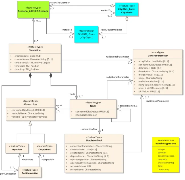
The Simulation Package represents therefore a first step towards linking semantic 3D city modelling and multi-domain co-simula-tion for urban energy modelling at urban scale. The UML diagram of the Simulation Package is presented in Figure 1. The structure of the package specifically targets co-simulation setups. At the same time, the design aims to be as generic as possible, enabling the application of the Simulation Package to a large variety of simulations tools and co-simulation environments. To this end, the following classes have been defined:
Instances of class Simulation are – from a hierarchical point of view – the top-level objects describing a co-simulation setup. An instance of class Simulation links all the relevant entities required to define the composition of several simulators. Fur-thermore, it enables to store additional parameters related to the orchestration of the simulators (i.e., configuration parameters for the co-simulation master algorithm) as generic attributes, con-tained in class GenericParameter. Class Simulation can op-tionally reference class Scenario from the CityGML Scenario ADE. The latter is conceived to allow for a systematic representa-tion of different scenarios within a city. For further details about the Scenario ADE the reader is invited to refer to the respective documentation (Agugiaro and Widl., 2018).
Instances of class Node represent the basic simulation units of a co-simulation setup. Class Node is an abstraction of the sim-ulation models and tools themselves, providing the information relevant to the initialization and execution of the simulation units. Information about the associated simulation model (e.g., name
or parameters) can be specified as generic attributes (through class GenericParameter). Furthermore, instances can be linked with CityGML objects derived from class CityObject, which allows to link them to domain-specific semantic data of a city model (useful, for instance, for automated model creation or vali-dation). A node object can represent a template node (i.e., attribute isTemplate is TRUE), or be itself derived from a parent template node. In the latter case, the additional relation derivesFrom is used.
The AbstractPort class is an abstract class that is imple-mented by InputPort and OutputPort. Instances of classes InputPort and OutputPort represent, respectively, the input and output variables of a simulation node used by a co-simulation tool to send/retrieve information to/from the associated simula-tor. In both cases, a port is intended to represent only a single scalar variable and must correspond to a variable in the associated simulation model with the same name and type. Like in the case of class Node, instances can be associated to CityGML objects derived from class CityObject.
The PortConnection class provides the possibility to link ports of different nodes, with each instance linking exactly one input port with one output port. This corresponds to the exchange of one scalar value between these two ports. The classes Node and PortConnection are the fundamental building blocks for defining the coupling between simulators in a co-simulation graph. The SimulationTool class contains information specific to the simulation tool used by a node. This information is stored sepa-rately from the simulation nodes in order to avoid duplications, as in a co-simulation several nodes may use instances of the same simulation tool. In order to be flexible enough, the class relies mostly on generic attributes (through class GenericParameter) next to a few basic attributes regarding mainly dependencies on the OS, version, etc.
2.2 Implementation as extension of the 3DCityDB
The 3D City Database or, in short, 3DCityDB (Yao et al., 2018) represents the reference implementation as database schema of the CityGML data model. It comes with a number of open-source tools that help with import and export operations of CityGML data. Initial work has been carried out recently to extend the 3DCityDB and add support for any ADEs (Yao and Kolbe, 2017), with con-crete examples of implementations for the Energy ADE (Agugiaro and Holcik, 2017), the Utility Network ADE (Boates et al., 2018, Den Duijn et al., 2018) and the Scenario ADE (Sch¨uler et al., 2018).
The 3DCityDB Simulation Package builds on top of the above-mentioned “extended” 3DCityDB and is currently implemented for PostgreSQL only. The overall goal of this extension is to fa-cilitate direct connection and usage of the 3DCityDB relational database by users and applications programmers. Besides the data-base schema, the 3DCityDB Simulation Package is shipped with a set of stored procedures that are automatically installed during the setup and that, conceptually, reflect the logic of the analogous ones shipped with the “standard” 3DCityDB. All database objects are stored within an instance of the 3DCityDB, and are all con-tained in a schema called sim pkg. All software resources, the accompanying documentation and a small test dataset are avail-able as open-source on GitHub (Agugiaro, G. and the 3DCityDB Development Team, 2018).
Figure 1. UML diagram of the Simulation Package: its classes are depicted in light beige, while the azure ones belong to the CityGML data model and the green one to the Scenario ADE
3. CASE STUDY AND IMPLEMENTATION This section provides a concrete example for the application of the Simulation Package presented in the previous section, demonstrat-ing how the data model can be applied to a specific co-simulation tool. As different co-simulation tools employ different ways of semantically representing co-simulation graphs, this example is not representative for the entirety of co-simulation tools. However, the example illustrates the mapping of the Simulation Package’s data model to a simulation tool’s specific representation of a co-simulation graph, showcasing the applicability and flexibility of the Simulation Package design. Furthermore, this section gives an overview about the implementation of a data access layer (DAL), which serves in the example as the actual interface between the database instance and the co-simulation tool.
3.1 The IntegrCiTy co-simulation toolchain
The IntegrCiTy project (IntegrCiTy Project Team, 2018) focuses on the development and implementation of an integrated decision-support environment for city planners and energy providers to
improve efficiency and resilience of energy supply infrastructures. An important asset in this decision support environment is a co-simulation toolchain, which allows to perform very detailed tech-nical assessments of proposed changes and extensions of energy supply infrastructure.
The core of the co-simulation toolchain is the OBNL software package, the OBvious Node Link co-simulator (OBNL Devel-opment Team, 2018). OBNL is an open-source Python package that provides a light-weight implementation of a co-simulation orchestrator for the synchronization of other simulators and the data exchange between them. OBNL has been specifically de-signed to work with Docker (Docker, Inc., 2018), which allows to package simulators and implemented models into executable containers. From a user perspective, setting up a co-simulation in the IntegrCiTy toolchain is reduced to defining the co-simulation graph, whose information is subsequently used to deploy the con-tainerized applications and execute the co-simulation with the help of the functionality provided by OBNL.
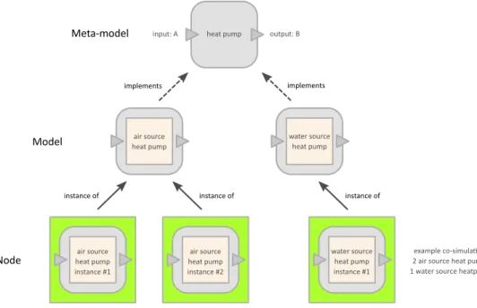
multi-Figure 2. Overview of the relation between meta-models, models and nodes in the IntegrCiTy co-simulation toolchain.
energy system simulations, an extended concept for representing simulators and models has been developed on top of OBNL’s generic notion of nodes and links. This enables a semantic repre-sentation of individual parts of the co-simulation setup, offering the user the advantages discussed in Section 1. This concept comprises the following elements:
• The fundamental building blocks is the so-called meta-model, which defines the generalized features of a specific compo-nent (or group of compocompo-nents) of the complete system. More precisely, it defines the attributes a simulation model of such a component (or group of components) has to implement. In terms of co-simulation, the attributes are basically the inputs and outputs of an individual simulation model.
• The abstract definition of a meta-model is implemented by so-called models. In general, several models may implement the same meta-model, expressing differences associated to the modelling approach (levels of detail, model of computation, etc.) or the physical component they represent (e.g., different technologies for the same type of component). Models are directly associated to containerized applications.
• Finally, a node is an actual instance of a model that is to be deployed as an individual simulator in a co-simulation. In general, several node instances of the same model can be present in a co-simulation.
• The inputs and outputs of nodes (implicitly defined through the linked meta-model) can be connected using links. Each link can associate exactly one input with one output. Figure 2 depicts the concept of meta-models, models and nodes and their relations, using a simple example. The meta-model on the top defines the template for all models representing a heat pump, including its attributes (one input attribute called A and one output attribute called B). This template is then im-plemented by two specific models (air source heat pump, water source heat pump), which can be instantiated as actual nodes in a co-simulation (other nodes and links not shown here).
3.2 Mapping the IntegrCiTy co-simulation graph to the Sim-ulation Package
The representation of co-simulation setups in the IntegrCiTy tool-chain cannot be mapped one-to-one to the scheme provided by the Simulation Package for two reasons:
• Semantic representation: IntegrCiTy’s notion of meta-mod-els, models and nodes is more complex than the concept provided by the Simulation Package, which only provides the classes Node and SimulationTool to represent the edges of a co-simulation graph.
• Specific parameterization: OBNL’s deployment requires cer-tain parameters (e.g., related to Docker), which are too spe-cific to be defined as part of the general Simulation Package scheme.
However, the design of the Simulation Package schema is rich and generic enough to allow an unambiguous mapping to IntegrCiTy’s representation of co-simulation graphs. Specifically, the Simula-tion Package’s concept of template nodes and generic parameters can be used to establish this mapping. In the following, the ratio-nale behind the mapping is explained:
• IntegrCiTy meta-models can be conceptually best matched using class Node of the Simulation Package. More precisely, meta models are represented as template nodes, with their attributes represented as input and output ports. As such, they are not intended to be directly linked to a specific co-simulation setup (and neither are their ports intended to be connected with other ports). They are rather intended as generic templates, collected in a “library” of meta-models. • IntegrCiTy’s notion of models is closely connected to the
ac-tual implementation of these models (typically using Docker containers). Hence, they can be conceptually best matched with class SimulationTool. The technical details of the model implementation that are not covered by attributes of
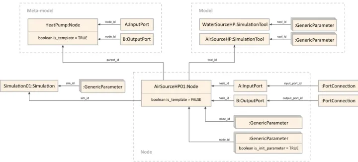
Figure 3. Example representation of nodeAirSourceHP01, linking to the associated meta-model (HeatPump), model (AirSourceHP) and co-simulation setup (Simulation01). Also shown are the node’s generic parameters, initial values and the port connections (links to other
ports not shown)
class SimulationTool can be represented with the help of generic attributes. Just like meta-models, model representa-tions are not linked to any specific co-simulation setup. • IntegrCiTy nodes can be directly mapped to class Node.
In-stances of nodes are basically clones of the corresponding meta-models, with the important difference that they are not template nodes. The node also replicates the same input and output ports (using the exact same name) as the correspond-ing meta-model, which can then be linked to port connections for building up the co-simulation graph.
• A distinctive feature of IntegrCiTy nodes are their associated set of initial values, which is a list of start values passed to the model at the start of the simulation. They can be rep-resented by generic parameters, with the Boolean attribute is init parameter set to TRUE. This allows to differenti-ate between other generic parameters and initial values. • All nodes and port connections of a co-simulation setup link
to an instance of class Simulation, basically connecting them to one co-simulation graph.
Figure 3 visualizes the mapping by giving an example based on Figure 2. It shows the representation of a node called AirSourceHP01, which instantiates model AirSourceHP and implements meta-model HeatPump.
3.3 The IntegrCiTy data access layer
Figure 4 visualizes the concept of the data access layer (DAL) developed for the IntegrCiTy toolchain (DBLayer Development Team, 2018). The goal is to bridge the gap between semantic 3D city models based on CityGML and technical assessments of multi-domain urban energy systems based on co-simulation. In this concrete instance, this is done by linking the extended 3DCityDB (including the Simulation Package) and the tools developed for the IntegrCiTy project.
The DAL implementation relies on state-of-the-art software pack-ages provided by Python and several new developments for the extended 3DCityDB (as described in Section 2.2):
Figure 4. Concept of the IntegrCiTy data access layer. • The DAL is based on functionality provided by the
SQLAl-chemy software package (SQLAlSQLAl-chemy Development Team, 2018). Apart from a toolkit to interact with SQL-based databases, it also offers a so-called Object Relational Map-per(ORM). This ORM presents a method of associating user-defined Python classes with database tables, and in-stances of those classes (objects) with rows in their corre-sponding tables. This mapping is done at runtime using meta-information from the database, which means that changes in the database scheme are automatically reflected in the DAL. • The extended 3DCityDB and the Simulation Package come
with functions for inserting/deleting objects to/from the data-base. Thanks to SQLAlchemy, these SQL functions can be easily mapped to Python functions, enabling a user-friendly interaction with the database as needed for IntegrCiTy work-flows.
• Furthermore, the extended 3DCityDB and the Simulation Package define so-called views linking information other-wise distributed over several tables. SQLAlchemy allows to interact with these views just like with ordinary tables, increasing the user-friendliness of data access and reducing the need for users to define complicated queries.
3.4 Example application
In the following, a minimalistic co-simulation setup is used to demonstrate the basic functionality of the DAL described in the
1 from ictdeploy import Simulator 2 # Create simulation.
3 sim = Simulator() 4 # Create meta-model.
5 sim.edit.add_meta(
6 name='BaseMeta', set_attrs=['a'], get_attrs=['b']
7 )
8 # Create model.
9 sim.edit.add_model(
10 name='BaseModel', meta='BaseMeta', ... 11 )
12 # Add nodes.
13 sim.edit.add_node(
14 name='Base0', model='BaseModel', 15 init_values={'c': 0.5}, ... 16 )
17 sim.edit.add_node(
18 name='Base1', model='BaseModel', 19 init_values={'c': 0.25}, ... 20 )
21 # Add links.
22 sim.edit.add_link(
23 get_node='Base0', get_attr='b', 24 set_node='Base1', set_attr='a' 25 )
26 sim.edit.add_link(
27 get_node='Base1', get_attr='b', 28 set_node='Base0', set_attr='a' 29 )
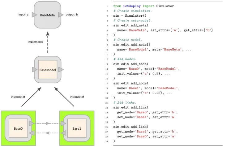
Figure 5. Definition of the simple co-simulation setup example.
previous section. After a short overview of the setup, three exam-ples show anticipated workflows for interacting with the database for users of the IntegrCiTy toolchain.
Please note that the presented examples have been kept simple on purpose in order to focus on the functionality provided by the DAL. For examples of more advanced apllications refer to the examples provided with the DAL implementation (DBLayer Development Team, 2018).
3.4.1 Simple co-simulation setup: Figure 5 shows the sim-ple co-simulation setup used further down (see Sections 3.4.3 and 3.4.4). The left side of the figure shows the conceptual com-position of the setup in terms of meta-models, models and nodes, with a graphical representation of the co-simulation graph at the bottom. The co-simulation setup comprises a system divided in two sub-systems, with each sub-system represented as an individ-ual node. Output b of node Base0 is linked to input a of node Base1 and vice versa, forming a cyclic dependency between the two nodes.
The right side of Figure 5 shows the pseudo code for defining the model within the IntegrCiTy toolchain (ICTDeploy Development Team, 2018). The depicted code is not complete, it rather only shows how to add meta-models (lines 5–7), models (lines 9–11), nodes (lines 13–20) and links (lines 22–29) to a co-simulation setup. Setting the initial value for a model parameter called c (not depicted on the left side of the figure) is shown in lines 15 and 19. Setting the values of other model or node parameters (especially related to the Docker implementation) are indicated only by ellipses (lines 10, 15 and 19). Setting of global simulation
parameters is not shown at all. The full example (including exe-cutable models) is available online (Puerto, P. and the ICTDeploy Development Team, 2018).
3.4.2 Accessing the extended 3DCityDB: In this section ba-sic examples of how to interact with the 3DCityDB through the implemented DAL are shown. The most basic functionality of the DAL is to provide access to the database. This is achieved through class DBAccess, which allows to connect to an instance of the extended 3DCityDB by calling function connect to citydb. The following examples demonstrates how to establish such a connection:
1 from dblayer import * 2
3 access = DBAccess() 4
5 connect = PostgreSQLConnectionInfo( 6 user='postgres', pwd='postgres',
7 host='localhost', port='5432', dbname='testdb'
8 )
9
10 access.connect_to_citydb( connect )
After a successful connection, class DBAccess offers several func-tions enabling a user-friendly interaction with the database. For instance, an important feature is that the SQL functions of the extended 3DCityDB can be called to insert new objects. The fol-lowing code snippet demonstrates how a new heat pump object is inserted with a reference to the building it belongs to (e.g., with building ID 1122) using SQL function insert heat pump (lines 1–5). Finally, these changes are committed permanently to the database (line 7).
1 hp_id = access.add_citydb_object( 2 insert_heat_pump, name='HEATPUMP_01', 3 nom_effcy=1.2, effcy_indicator='COP', 4 inst_in_ctyobj_id=1122
5 )
6
7 access.commit_citydb_session()
In the context of creating co-simulation setups it is probably most important to have easy access to data already available in the data-base. For this, the extended 3DCityDB provides in many cases con-venient views. The following example shows how this can be done in the case of heat pump data. First, class HeatPump is associated with the view citydb view.nrg8 conv system heat pump (lines 1–4). This association is then used to refine condi-tions for querying the database (lines 6–9). Finally, function get citydb objects is called to retrieve data from the speci-fied view with the specispeci-fied query conditions (lines 11–13). Lines 15–16 show that the attributes of the retrieved objects indeed reflect the content of the specified view.
1 HeatPump = access.map_citydb_object_class(
2 'HeatPump', schema='citydb_view',
3 table_name='nrg8_conv_system_heat_pump' 4 ) 5 6 conditions= [ 7 HeatPump.name=='HEATPUMP_01', 8 HeatPump.nom_effcy==1.2 9 ] 10 11 heatpumps = access.get_citydb_objects( 12 'HeatPump', conditions=conditions 13 ) 14 15 effcy_ind = heatpumps[0].effcy_indicator 16 heatpump_id = heatpumps[0].id
3.4.3 Interfacing with the Simulation Package: The DAL also implements the mapping of the Simulation Package scheme to IntegrCiTy’s concepts for representing co-simulation graphs (as defined in Section 3.2), providing basically a persistence layer for co-simulation setups. For storing co-simulation setups to the extended 3DCityDB, the DAL provides class DBWriter. Upon connecting to the database (line 1), a co-simulation setup can be assigned a name and written to the database with the help of a single command. Lines 3–5 show how this is done for the exam-ple from Section 3.4.1. The parameters in line 4 indicate that a co-simulation setup already defining meta-model MetaBase and model BaseModel has been previously written to the same data-base (otherwise the corresponding parameters should be omitted).
1 writer = DBWriter( connect ) 2
3 writer.write_to_db( sim, 'TestSim1',
4 write_meta_models=False, write_models=False
5 )
For reading co-simulation setups from the extended 3DCityDB, the DAL provides class DBReader. Upon connecting to the data-base (line 1), a co-simulation setup stored in the datadata-base can be referred to by name and retrieved with the help of a single command (line 3). In the example below, which simply reads back the co-simulation setup written in the previous example, the resulting object sim read would be identical to object sim from the example in Section 3.4.1.
1 reader = DBReader( connect ) 2
3 sim_read = reader.read_from_db( 'TestSim1' )
3.4.4 Associate co-simulation graphs with 3DCityDB data: In the current IntegrCiTy toolchain, the association of co-simula-tion graphs with 3DCityDB data happens first and foremost by using the available information to parametrize simulation models. In the context of urban energy systems simulation, this comprises not only scalar model parameters (e.g., U-values for walls) but also time-series data as provided via the Energy ADE (e.g., electrical load profiles).
The rather trivial approach for such an association is to directly retrieve certain values with the help of the DAL (according to the example in Section 3.4.2) and setting them as initial values when defining the co-simulation graph (compare lines 15 and 19 in Figure 5). However, IntegrCiTy’s DAL and the Simula-tion Package also allow to persistently store associaSimula-tions with attributes of 3DCityDB objects and generic parameters. This is demonstrated in the following pseudo code snippet, which basi-cally extends the setup shown in Figure 5 by defining an instance of class AssociateCityDBObject (lines 4–7) and assigning it to parameter c of node Base0 (lines 10–11).
1 table = 'citydb_view.nrg8_conv_system_heat_pump' 2 attribute = 'nom_effcy' 3 4 associate_object = AssociateCityDBObject( 5 table_name=table, 6 object_id=heatpump_id, 7 column_name=attribute 8 ) 9
10 sim.edit.nodes.loc[ 'Base0' ].init_values[ 'c' ] = \ 11 associate_object
12
13 writer.write_to_db( sim, 'TestSim2',
14 write_meta_models=False, write_models=False 15 )
Please note that in above example the resulting co-simulation graph object sim would not be valid to deploy an actual co-simulation (because parameter c is not associated to a scalar or vector). However, when writing the setup to the database, the association of parameter c with the corresponding table attribute is stored persistently. Furthermore, when reading this stored co-simulation setup from the database (using class DBReader), the association is automatically resolved. This means that parameter c in the resulting co-simulation graph object would have the corre-sponding numerical value and the object would be valid to deploy an actual co-simulation.
4. CONCLUSION AND OUTLOOK
This paper has presents initial work carried out to link semantic 3D city modelling and multi-domain co-simulation for urban energy modelling at urban scale. Starting from the CityGML data model (and the derived 3DCityDB as database schema implementation), a Simulation Package extension for the 3DCityDB has been con-ceived and implemented. The Simulation Package is meant to model and store in an integrated way additional meta-information which is required to execute an actual simulation or co-simulation. In the latter case, not only configurations are required for each individual simulator, but also specific information regarding the coupling and orchestration of several simulator instances.
In the context of project IntegrCiTy, the Simulation Package has been adopted in order to build on top of it a Python-based data ac-cess layer allowing for linkage with an OBNL-based co-simulation tool. It lays the foundation for a two-way connection between a de-tailed city-scale data model and simulation models of centralised and distributed complex energy systems, and it tries to answer the lack of extensible and adaptable cross-domain ontologies. Work carried out within the IntegrCiTy project is a first step to-wards linking semantic 3D city modelling and multi-domain co-simulation for urban energy modelling at urban scale. Although at a rather initial state of development, the assumption is that the developed tools are generic and flexible enough to be used also in other contexts. The wish is that the availability of a common, shared data model and the accompanying data access layer will contribute and foster adoption and further improvement of the Simulation Package in a sort of virtuous circle.
ACKNOWLEDGEMENTS
Research and implementation work presented in this paper has been carried out within the project IntegrCiTy (IntegrCiTy Project Team, 2018) (ERA-NET Cofund Smart Cities and Communities call). In Switzerland, it is funded by the Swiss Federal Office of Energy (contract SI/501404-2), as well as by the industrial and institutional partners of the project. In Austria, it is funded by the Austrian Federal Ministry for Transport, Innovation and Technol-ogy within the framework of the ENERGIE DER ZUKUNFT/JPI Urban, with support from the European Union’s Horizon 2020 re-search and innovation programme. Please visit the project website for a full list of project consortium partners.
REFERENCES
Agugiaro, G. and Holcik, P., 2017. 3D City Database extension for the CityGML Energy ADE 0.8 PostgreSQL Version – Documen-tation. https://github.com/gioagu/3dcitydb_ade/blob/ master/02_energy_ade/manual.
Agugiaro, G. and the 3DCityDB Development Team, 2018. 3D City Database “Plus” Software. https://github.com/ gioagu/3dcitydb_ade.
Agugiaro, G. and Widl., E., 2018. CityGML 3D City Data-base Simulation Package, PostgreSQL Version – Documenta-tion. https://github.com/gioagu/3dcitydb_ade/tree/ master/05_simulation_pkg/documentation.
Agugiaro, G., Benner, J. et al., 2018. The energy application domain extension for citygml: enhancing interoperability for ur-ban energy simulations. Open Geospatial Data, Software and Standards3(1), pp. 2.
Boates, I., Agugiaro, G. and Nichersu, A., 2018. Network mod-elling and semantic 3D city models: how mature is the Utility Network ADE? A test case based on a water network. In: ISPRS Ann. Photogramm. Remote Sens. Spatial Inf. Sci., GeoDelft 2018 Conference, The Netherlands.
DBLayer Development Team, 2018. The DBLayer Pack-age – IntegrCiTy Data Access Layer. https://github.com/ IntegrCiTy/obnl.
Den Duijn, X., Agugiaro, G. and Zlatanova, S., 2018. Modelling below- and above-ground utility network features with the citygml utility network ade: experiences from rotterdam. In: ISPRS Ann. Photogramm. Remote Sens. Spatial Inf. Sci., GeoDelft 2018 Con-ference, The Netherlands.
Docker, Inc., 2018. Docker containerization platform. https: //www.docker.com/.
Gr¨oger, G. and Pl¨umer, L., 2012. CityGMLinteroperable semantic 3D city models. ISPRS J Photogramm Remote Sens. 71, pp. 12–33. ICTDeploy Development Team, 2018. IntegrCiTy co-simulation deployment API. https://github.com/IntegrCiTy/ ictdeploy.
Ilic, M., Xie, L. et al., 2008. Modeling future cyber-physical energy systems. In: 2008 IEEE Power and Energy Society General Meeting - Conversion and Delivery of Electrical Energy in the 21st Century, pp. 1–9.
IntegrCiTy Project Team, 2018. Decision-support environ-ment for planning and integrating multi-energy networks and low-carbon resources in cities. http://iese.heig-vd.ch/ projets/integrcity.
Kutzner, T. and Kolbe, T., 2016. Extending semantic 3d city mod-els by supply and disposal networks for analysing the urban supply situation. In: L¨osungen f¨ur eine Welt im Wandel, Dreil¨andertagung der SGPF, DGPF und OVG, 36. Wissenschaftlich-Technische Jahrestagung der DGPF, pp. 382–394.
Lund, H., Werner, S. et al., 2014. 4th generation district heating (4gdh): Integrating smart thermal grids into future sustainable energy systems. Energy 68, pp. 1–11.
OBNL Development Team, 2018. OBvious Node Link co-simulator (OBNL) Software. https://github.com/ IntegrCiTy/obnl.
Puerto, P. and the ICTDeploy Development Team, 2018. Minimal dummy example with ICTDeploy. https://github.com/IntegrCiTy/DemoDeployICT/blob/ master/MinimalExample.ipynb.
Sch¨uler, N., Agugiaro, G. and Marechal, F., 2018. Linking in-teractive optimisation for urban planning with semantic 3d city models. In: ISPRS Ann. Photogramm. Remote Sens. Spatial Inf. Sci., GeoDelft 2018 Conference, The Netherlands.
SQLAlchemy Development Team, 2018. The SQLAlchemy SQL Toolkit and Object Relational Mapper Software, Version 1.2. http://docs.sqlalchemy.org.
Van Beuzekom, I., Gibescu, M. and Slootweg, J., 2015. A re-view of multi-energy system planning and optimization tools for sustainable urban development. In: IEEE Eindhoven PowerTech, pp. 1–7.
Widl, E., Jacobs, T., Schwabeneder, D. et al., 2018. Studying the potential of multi-carrier energy distribution grids: A holistic approach. Energy 153, pp. 519–529.
Yao, Z. and Kolbe, T., 2017. Dynamically extending spatial databases to support CityGML application domain extensions using graph transformations. In: 37. Wissenschaftlich-Technische Jahrestagung der DGPF in W¨urzburg - Publikationen der DGPF, Vol. 26, pp. 316–331.
Yao, Z., Nagel, C. et al., 2018. 3DCityDB - A 3D Geodatabase Solution for the Management, Analysis, and Visualization of Se-mantic 3D City Models based on CityGML. Open Geospatial Data, Software and Standards.