HAL Id: tel-02007359
https://tel.archives-ouvertes.fr/tel-02007359
Submitted on 5 Feb 2019HAL is a multi-disciplinary open access archive for the deposit and dissemination of sci-entific research documents, whether they are pub-lished or not. The documents may come from teaching and research institutions in France or abroad, or from public or private research centers.
L’archive ouverte pluridisciplinaire HAL, est destinée au dépôt et à la diffusion de documents scientifiques de niveau recherche, publiés ou non, émanant des établissements d’enseignement et de recherche français ou étrangers, des laboratoires publics ou privés.
3D visualization and interactive image manipulation for
surgical planning in robot-assisted surgery
Mohammad Reza Maddah
To cite this version:
Mohammad Reza Maddah. 3D visualization and interactive image manipulation for surgical planning in robot-assisted surgery. Human-Computer Interaction [cs.HC]. Ecole nationale supérieure Mines-Télécom Atlantique; Wright state university (Dayton, Ohio), 2018. English. �NNT : 2018IMTA0079�. �tel-02007359�
T
HESE DE DOCTORAT DE
L
’É
COLEN
ATIONALES
UPERIEUREM
INES-T
ELECOMA
TLANTIQUEB
RETAGNEP
AYS DE LAL
OIRE-
IMT
A
TLANTIQUECOMUE UNIVERSITE BRETAGNE LOIRE ECOLE DOCTORALE N°601
Mathématiques et Sciences et Technologies de l'Information et de la Communication Spécialité : Informatique
3D Visualization and Interactive Image Manipulation for Surgical
Planning in Robot-assisted Surgery
Thèse présentée et soutenue à Wright State University, le 27 septembre 2018 Unité de recherche : LS2N
Thèse N° : 2018IMTA0079
Par
Mohammad Reza MADDAH
Rapporteurs avant soutenance :
Guillaume MOREL, professeur, Sorbonne Université Erwan KERRIEN, chercheur, INRIA
Composition du Jury :
Président : Naly Rakoto, maître assistant, IMT Atlantique
Examinateurs : Katherine LIN, surgeon, Greene County General Hospital Guillaume MOREL, professeur, Sorbonne Université Erwan KERRIEN, chercheur, INRIA
Dir. de thèse : Caroline CAO, professeur, Wright State University Co-dir. de thèse : Cédric DUMAS, maître assistant, IMT Atlantique
Résumé en Français
Le chapitre 1 (Introduction, 5 pages) décrit le contexte général (la question du placement des trocarts en chirurgie miniinvasive) et situe les objectifs : assister les équipes chirurgicales dans cette tâche. Il décrit ensuite brièvement, mais clairement, les trois contributions principales : (1) développer un système complet pour le placement des trocarts (2) mesurer le déplacement des organes lors de l’insufflation d’un patient en chirurgie laparoscopique (3) réduire le recours à l’imagerie préopératoire. Il donne enfin le plan du reste du manuscrit. Le chapitre 2 (Background and Research objectives, 13 pages) propose une rapide description de la chirurgie laparoscopique et du système da Vinci puis une revue de la littérature sur la question du choix de l’emplacement des incisions, d’abord en chirurgie manuelle, puis plus spécifiquement en chirurgie télérobotique. Enfin, une description globale de la procédure de sélection des points d’entrée dans le patient est décrite, en même temps que les questions qui se posent aux différentes étapes. Le choix est porté sur l’hystérectomie, qui est l’une des interventions les plus fréquemment pratiquées par les équipes utilisant le robot da Vinci. Le chapitre 3 (General Approach (Methodology), 63 pages) regroupe la description des méthodes et algorithmes utilisés pour mettre en place le système de placement des trocarts. La partie 3.1 traite d’imagerie 3D. En préopératoire, un scanner est utilisé pour extraire, via une segmentation par seuillage, l’enveloppe 3D extérieure du corps. De plus, l’organe cible est également segmenté manuellement via un outil de manipulation d’images. Le modèle ainsi obtenu des deux surfaces est appelé modèle interne. En peropératoire, un nuage de points de l’abdomen gonflé est enregistré via une Kinect au bloc opératoire. Il fournit l’enveloppe extérieure du patient, qui est ensuite transformé en surface (algorithme alpha shape) et constitue le modèle externe. Un recalage est fourni en repérant sur chaque modèle (interne et externe) quatre points saillants supposés rigidement liés car appartenant au bassin. La transformation rigide reliant ces points est calculée ce qui permet de placer l’organe dans le modèle de surface peropératoire (dit externe) pour finalement former un modèle dit « spécifique au patient ». L’hypothèse sousjacente est que l’organe reste indéformé et immobile par rapport au bassin lors du pneumopéritoine. L’approche et les outils sont classiques, les explications claires. On comprend que pour l’essentiel, le candidat a utilisé des outils existants qu’il a appliqués à son problème particulier. Dans la partie 3.2, les modèles mathématiques utilisés pour décrire la géométrie des bras du robot da Vinci sont donnés. Dans la partie 3.3, le problème de positionnement des points d’incision est défini mathématiquement. Le modèle du patient étant construit, la base du robot étant supposée positionnée, le placement des points d’entrée est l’inconnue. L’indice de performance retenu est la manipulabilité cinématique. L’optimisation suppose de définir une solution initiale (best guess).Dans la partie 3.4, l’auteur revient sur l’hypothèse de rigidité qui prévalait dans la partie modélisation. Il note que lors de l’insufflation, les organes ne sont pas immobiles par rapport au bassin. Il conduit donc une expérimentation sur modèle animal (porcin) : les animaux sont imagés avant et après pneumopéritoine. Les variations de volumes sont mesurées ainsi que la variation de position du centre géométrique de certains organes, segmentés manuellement par un radiologue vétérinaire. L’influence sur l’accessibilité est discutée. Pour des questions de taille d’organe visible dans des animaux jeunes, le principe est de retenir le déplacement moyen mesuré des reins des animaux pour estimer le déplacement de l’utérus. La partie 3.5 traite du processus d’optimisation en luimême. Il s’agit d’un problème multi objectif, traité en traçant un front de Pareto en intégrant un objectif d’efficacité (traduisant le volume de travail) et un objectif de noncollision. Les collisions considérées sont celles des instruments à l’intérieur du patient. Le chapitre 4 (Measurement and Results, 30 pages) montre les résultats numériques d’application des méthodes proposées au chapitre 3. Sur les sept patientes initialement incluses dans cette étude, les 4 premières sont retenues du fait de la meilleure qualité des images 3D. Ce chapitre, essentiellement descriptif, montre l’application pas à pas des procédures. Le chapitre 5 (Validation and Verification, 11 pages) reprend les résultats obtenus avec les données des 4 patientes et les compare à la position sélectionnée par les chirurgiens lors des procédures réelles. La comparaison se fait d’abord directement (mesure des distances entre les points d’incision recommandés par l’algorithme et ceux pratiqués par les chirurgiens). Elle fait apparaître des différences de plusieurs centimètres (jusqu’à 7 pour l’endoscope). Cette différence observée n’indique pas quelle est la meilleure solution. C’est pourquoi une expérience supplémentaire est mise en place en laboratoire par l’auteur. Un fantôme anatomique est cette fois utilisé et les tâches sont représentatives de la gestuelle lors d’une hystérectomie. Le temps de réalisation des tâches avec des positionnements de bras et de point d’entrée optimaux et sousoptimaux sont comparés. Ils montrent un gain certain avec un placement planifié par les outils d’optimisation proposés dans cette thèse. Enfin, une dernière proposition concerne l’utilisation de valeurs moyennes de positionnement des organes issues de mesures faites sur diverses patientes afin d’éviter le recours à une imagerie préopératoire.
Le chapitre 6 est une conclusion. Les contributions sont résumées, les limitations sont listées et des perspectives sont esquissées.
Contents
1 Introduction 1
1.1 Motivation ……….………...……….. 2
1.2 Contributions………..………..……….………....………... 3
1.2.1
Developing a comprehensive port placement system
Laparoscopic Surgery.. 31.2.2 Measuring the organs’ motion due to insufflation………... 4
1.2.3 Reducing the need for pre-operative medical images ………..…………... 4
1.3
Outline of Dissertation……
………..….……...……… 42 Background and Research Objectives 6 2.1
Literature Review...
………...…………...……….. 62.1.1 Laparoscopic Surgery………... 6
2.1.1.1 Advantages and Disadvantages………
82.1.2 Robotic Surgery………... 9
2.1.3 Port Placement………..………... 11
2.2 Research Objectives………...……...……….. 15
2.3 Chapter Summary….………...……….. 18
3 General Approach (Methodology) 19 3.1 Patient-Specific Model……….……….……… 20
3.1.1 External 3D Model……….……….. 22
3.1.1.1 3D Scanners: Kinect………….………
233.1.2 Internal 3D Model……….……….. 28
3.1.2.1 MRI, CT Scan Data Structure...………
293.1.2.2 Segmentation Method……….………
303.1.2.3 Surface Reconstruction Algorithm (Alpha Shape)………...
333.1.2.4 Image Analysis (ITK) and Visualization Toolkit (VTK)……….
353.1.2 Alignment Technique……….……….. 37
3.2 Robot Model……….……….……… 41
3.2.1
da Vinci Manipulator Design
………...……….. 423.2.3
The Inverse Kinematics Problem in Laparoscopic Surgery………..
473.3
Port Placement: Problem definition
………….……….………….……….. 533.4
Target Organ Estimation ……...…..
………….……….………….……….. 573.4.1
Animal Subjects………..
………...……….. 573.4.2
Creating Patient 3D Model….
………...……….. 593.4.3
Volume and Target Region Measurements
……...………...……….. 593.4.4
Organ shift (Displacement) Measurements...
…...………...……….. 613.5 Optimization……….……….……… 67
3.5.1
Collision and efficiency Index (Intersection of the cones)
……….. 703.5.2
Multi-Objective Optimization: Pareto-Optimal Solution..
……….. 743.6 Chapter Summary……….……….……… 75
4 Measurements and Results 77 4.1
Subjects and Experimental Set-up
……...………..……….……….. 774.2
Robot Positioning and
Port Placement………..…..………….. 794.2.1 Mesh Simplification……….. 79
4.2.2 Robot Positioning…...……….. 80
4.2.3 Port Placement……...……….. 103
4.3 Chapter Summary………..……….……….………….. 107
5
Validation and Verification
108 5.1 Verification………...………..……….……….. 1085.2 System Validation.………...………..……….……….. 111
5.2.1 Experimental Setup...……….. 112
5.2.2 Task………....……….. 112
5.3 Reducing Pre-Operative Planning in Port Placement System ...………..……….. 116
5.4 Chapter Summary………..……….……….………….. 118
6
Conclusion and Future research
120 6.1 Conclusion……...………..……….……….………….. 1206.2 Limitations and Future Research Directions
………..
…..….……….………….. 121List of Figures
2.1 (a) The arrangement of the endoscope and surgical instruments in a laparoscopic surgery, (b) a schematic of a hysterectomy procedure for removing the uterus from the patient’s
body……….……….………….………... 7
2.2 da Vinci Si HD surgical system……… 9
2.3 Left: Four degrees of freedom at the entry port (three rotations and one translation), Right: da Vinci Endo-Wrist design of the surgical tool tip...……….… 10
2.4 Working volume of a robot manipulator (surgical tool) and the endoscope in a hysterectomy procedure………... 11
2.5 Working flow for selecting the ports in a laparoscopic procedure……….……… 15
2.6 The proposed plan for planning ports in a laparoscopic surgery………... 17
3.1 Workflow to construct the patient-specific model in “combined” method………... 21
3.2 Experimental set-up to capture 3D points from the abdominal surface in the operating room…… 21
3.3 Schematic representation of Kinect depth-disparity relation……… 23
3.4 Kinect coordinate system (attached to the camera)………... 25
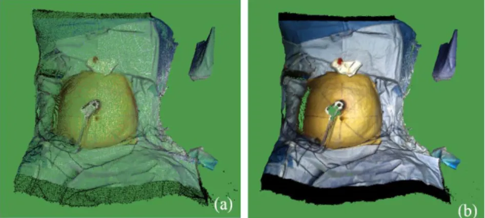
3.5 (a) A sample of 3D colored points, captured by Kinect in the operating room, (b) A sample of generated 3D mesh by Kinect fusion (from a patient’s abdominal surface)……….. 26
3.6 Kinect fusion user interface……….. 26
3.7 A sample set of 3D points and the generated 3D mesh by alpha shape algorithm (external 3D model)……….. 27
3.8 Algorithm to construct a 3D internal model……….. 28
3.9 Accepted triangulation: A and D do not lie in the interior of the circles passing through “BCD” (red circle) and “ABC” (black-dashed circle), respectively. Rejected triangulation: C lies in the interior of the circle passing through “ABD” (green circle)……….. 34
3.10 ITK pipeline………. 35
3.11 ITK-VTK pipeline (flow chart) to generate a 3D internal model………... 35
3.12 VTK pipeline……… 36
3.14 The corresponding points on the surface of two 3D objects……….. 38
3.15 (a) Natural landmarks on the internal model, (b) Two points on the 10th rib of the rib cage, (c) Two points on the pelvic bone: Anterior superior iliac (ASI)……….... 39
3.16 (a) Corresponding points on the internal model, (b) Corresponding points on the external model… 40 3.17 The result of aligning the external model with the internal model: The patient-specific model: (a) Front view, (b) Side view………... 41
3.18 da Vinci Si robot………... 42
3.19 da Vinci Xi robot………...………... 43
3.20 Actuated (active) joints in da Vinci robot………...……….. 43
3.21 D-H parameters of a revolute joint (i)………... 44
3.22 Si model Endoscope………...……….. 45
3.23 Si model Arm No.1 & No.2………...………... 45
3.24 Si model Arm No.3………... 46
3.25 Actuated joints frames in da Vinci Si……… 48
3.26 (a) Parallelogram design of the Si manipulator, (b) Parallelogram design of the Xi manipulator….. 52
3.27 4-DOF pivoting motion at RCM point (tilt (pitch), spin (yaw), and pan (roll) rotations)………….. 52
3.28 Schematic of the robot manipulator (active joints) to perform the operation……… 53
3.29 “Side” and “between legs” docking in a hysterectomy procedure………. 55
3.30 Accessible points (in green) for the endoscope, positioned at (X=0.0, Y=0.7 m, Z= 0.0)…………. 56
3.31 Points with a manipulability greater than the mean value (in blue) for the endoscope, positioned at (X=0.0, Y=0.7 m, Z= 0.0)……… 57
3.32 The experimental set-up of the pigs scanning in the MRI room……… 58
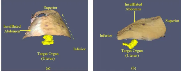
3.33 3D model of the abdomen: (a) pre-insufflation, (b) after insufflation………... 59
3.34 (a) Manual segmentation on a pre-insufflation slice, sagittal view, (b) Manual segmentation on a post-insufflation slice, sagittal view………. 59
3.35 (a) The spleen in pig 2 before insufflation, (b) The deformed spleen in pig 2 after insufflation…… 60
3.36 pig 2 vertebras: (a) Pre-insufflation, (b) Post-insufflation……… 62
3.37 Pig 2: the result of registration: (a) Coronal view, (b) Sagittal view……….. 63
3.38 (a) da Vinci (Si) robot manipulator’s three actuated joints (L0, L1, and L2), (b) Kinematic schematic of the robot manipulator, docked on the abdomen of pig 2………... 64
3.39 Planar motion of the left kidney’s centroid due to intra-abdominal pressure (insufflation)………... 65 3.40 Pig 2’s accessible points (on the insufflated abdominal surface) for the robot manipulator: (a)
accessible points when the target is located in the post-insufflation position, yellow point, (c) comparison of the accessible points (with two different target positions)………. 3.41 M(t1), M(t2), M(t3), and M(te) regions on the patient’s abdominal surface in a hysterectomy
procedure: M(t1) is the points in yellow, M(t2) is the points in blue, M(t3) is the points in red, and
M(te) is the points in green……… 68
3.42 The working volume around the target organ (uterus) in a hysterectomy procedure………. 71 3.43 The target volume (sphere) around the target organ (uterus) in a hysterectomy procedure………... 71 3.44 The overlap between the working volumes of two surgical tools in a hysterectomy procedure…… 72 3.45 The overlap between the working volume of two surgical tools. The cones’ axes cross at a
common point, P, with the apexes of the cones in an equal distance from P……….. 72 3.46 A 3D-dimensional cone filled with 3D points, A: cone’s apex R: cone’s bottom radius…………... 73 3.47 An algorithm for checking if a point, P, is inside a cone (H is the cone’s height, and R is the radius
of the cone’s bottom)………..……….. 73
3.48 The result of the discretization method to find the intersection volume of two working volumes: (a) Two intersecting cones (working volumes), (b) The cones’ intersection (overlap) is
highlighted in yellow……… 74
3.49 A sample of Pareto front (in blue) in the port placement problem………. 75 4.1 The reference frame (attached to the patient’s body, and centered at the umbilicus), Z axis: from
legs to the head, X: from left to the right, Y: from back to front. (a): front view, (b) side view…….. 78 4.2 (a) A patient model (Patient3), simplified by the clustering decimation method, (b) magnified
view of the simplified patient model (Patient3)……… 80
4.3 The angles between the robot arms for avoiding collision in da Vinci Si model, recommended by
the manufacturer (Intuitive)……….. 81
4.4 Patient1: -0.15 < z < 0.21 and -0.15 < x < 0.15……….. 82
4.5 Relationship between the endoscope position in Y direction and the number of accessible points
on the patient model (Patient1)………. 83
4.6 Relationship between the endoscope position in Y direction and the average of the manipulability
index on the patient model (Patient1)………... 83
4.7 Patient1-Pareto front of the endoscope arm, positioned at x= 0.0, 0.1 < y < 0.95, z=0.0…………... 84 4.8 Patient1-Pareto front of the endoscope arm, positioned at x= 0.0, y=0.75, -0.3 < z < 0.20………… 85 4.9 (a) accessible points (in green) on the patient model for the endoscope arm, positioned at (0.0,
0.75, -0.15), (b) accessible points with manipulability index > 0.2 (in blue) for the endoscope, (c) patient model, accessible points are in green, and the accessible points with manipulability index 85
> 0.2 are in blue………. 4.10 Patient1-Pareto front of ArmNo1, positioned at x= 0.46, 0.15 < y < 0.70, z=0.0………... 87 4.11 Patient1-Pareto front of ArmNo2, positioned at x= -0.46, 0.15 < y < 0.70, z=0.0………. 87 4.12 Patient1-Pareto front of ArmNo3, positioned at x= -0.65, 0.0 < y < 0.40, z=0.0………... 88 4.13 (a) accessible points (in green) on the patient model for ArmNo1, positioned at (0.46, 0.45,
-0.10). The accessible points with manipulability index > 0.1687 are shown in blue, (b) accessible points (in green) on the patient model for ArmNo2, positioned at (-0.46, 0.45, 0.0). The accessible points with manipulability index > 0.1684 are shown in blue, (c) accessible points (in green) on the patient model for ArmNo3, positioned at (-0.65, 0.15, -0.15). The accessible points with
manipulability index > 0.1894 are shown in blue……….. 90
4.14 Accessible and preliminary points (in green and blue) on the Patient2 model: (a) The endoscope positioned at (0.0, 0.75, -0.20), (b) ArmNo1 positioned at (0.46, 0.50, -0.30), (c) ArmNo2 positioned at (-0.46, 0.50 -0.30), (d) ArmNo3 positioned at (-0.65, 0.20, -0.05)………... 94 4.15 Accessible and preliminary points (in green and blue) on the Patient3 model: (a) The endoscope
positioned at (0.0, 0.75, -0.20), (b) ArmNo1 positioned at (0.46, 0.45, -0.30), (c) ArmNo2 positioned at (-0.46, 0.45, -0.30), (d) ArmNo3 positioned at (-0.65, 0.15, 0.00)………... 98 4.16 Accessible and preliminary points (in green and blue) on the Patient4 model: (a) The endoscope
positioned at (0.0, 0.70, -0.30), (b) ArmNo1 positioned at (0.46, 0.45, -0.30), (c) ArmNo2 positioned at (-0.46, 0.40, -0.30), (d) ArmNo3 positioned at (-0.65, 0.05, 0.00)………... 102 4.17 The preliminary points for the endoscope (in green), ArmNo1 (in red), ArmNo2 (in blue), and
Arm3 (in yellow) on the Patient1 3D model……….. 103
4.18 Patient1 optimal port location: the endoscope ports (in green), ArmNo1 ports (in red), ArmNo2
ports (in blue), and ArmNo3 ports (in yellow)……….. 104
4.19 Patient1 optimal port location, obtained from the averaging the points in each cluster………. 104 4.20 Patient1- optimal port location, obtained from selecting the ports in order ……….……. 105 4.21 Patient2- (a) optimal port location: the endoscope ports (in green), ArmNo1 ports (in red),
ArmNo2 ports (in blue), and Arm3 ports (in yellow), (b) The final solution by choosing the ports
in order ………...……….. 106
4.22 Patient3- (a) optimal port location: the endoscope ports (in green), ArmNo1 ports (in red), ArmNo2 ports (in blue), and Arm3 ports (in yellow), (b) The final solution by choosing the ports
in order………...……….. 106
4.23 Patient4- (a) optimal port location: the endoscope ports (in green), ArmNo1 ports (in red), ArmNo2 ports (in blue), and Arm3 ports (in yellow), (b) The final solution by choosing the ports 107
in order……….……… 5.1 Actual ports in red and the calculated ports in blue for the endoscope, ArmNo1, and ArmNo2 on
the patient model (a) Patient1 (b) Patient2 (c) Patient3 (d) Patient4……….………. 109 5.2 (a) The body phantom outer shape (b) The body phantom, with a target embedded (c) The body
phantom base, the cuboid, and the target ……… 111
5.3 Target in different positions on the phantom base ……….. 112
5.4 (a) The robot arms docked to the phantom (b) The position of ArmNo1, ArmNo2, and the
endoscope relative to the phantom ………...……… 112
5.5 The robot entry ports: (a) Target positioned at the right corner (b) Target positioned at the middle (c) Target positioned at the bottom (d) The entry ports, determined by the
surgeons………...……… 113
5.6 The designed task to pick the target that is covered by the X shape tape in the body
phantom…...………. 114
5.7 A test patient-specific 3D model ………. 114
5.8 (a) the actual accessible and preliminary points for the endoscope positioned at (0.0, 0.75, 0.0), (b) the estimated accessible and preliminary points for the endoscope positioned at (0.0, 0.75, 0.0), (c) the actual accessible and preliminary points for ArmNo1 positioned at (0.0, 0.55, 0.0), (d) the estimated accessible and preliminary points for ArmNo1 positioned at (0.0, 0.55, 0.0)…... 118
Acknowledgement
I would like to express my gratitude to my advisor Dr. Caroline GL Cao at Wright State University for her continues support of my Ph.D. study and related research, for her patience, motivation, and deep knowledge. Her constant guidance helped me in all time of research, and I learned a lot from her. I would like to thank you for encouraging my research and allowing me to grow as a research scientist!
I wish to thank Dr. Cedric Dumas, my advisor at IMT Atlantique in Nantes, France. He provided me a deeper understanding of the computer science part of the project. He also helped me to have a very good collaboration with other engineering disciplines in the lab. I cannot thank you enough.
My sincere thanks go to Dr. Damien Chablat at LS2N who helped me a lot in robotic part of my research project. I also must thank Dr. Olivier Gauthier for his sincere assistance for data collection at école nationale vétérinaire de Nantes (ONIRIS).
A special thanks to Dr. Jean-Marc Classe at Institut de Cancérologie de l'Ouest (ICO) who provided me access to the clinical facilities for my data collection. Thank you so much. Also, I would like to thank Dr. Isabelle Jaffre and the surgical staff at ICO for their collaboration to collect data in Nantes, France. A special thanks to Dr. Keith Watson, Dr. Katherine Lin, and Dr. Minia Hellan and the surgical staff at Miami Valley hospital in Dayton (OH, USA) who helped me a lot for data collection.
I also want to thank people in robotic research group at IMT Atlantique in France for the discussions in robotic part of my project.
Last but not the least, I would like to thank my family: my mother and to my brother and sister for supporting me spiritually throughout writing this thesis and my life in general.
I dedicate this dissertation to my mother for nursing me with affections and love and her
dedicated partnership for success in my life.
Chapter 1
Introduction
In robotic minimally invasive surgery (MIS), port placement is a pre-operative surgical procedure in which the surgeon makes three or four small incisions (ports) on the patient’s body in the operating room [1]. The surgical instruments (including an endoscope to see inside the patient) are inserted into the patient’s body through the ports, and the tools and the endoscope are connected to the robot arms, allowing the surgeon to perform the operation remotely. The most commonly used robot in MIS procedures is da Vinci, which has three main components: the robot (including three manipulators and one endoscope), a monitoring tower, and a console for controlling the robot manipulators through a master-slave telecommunication system [2]. In robotic MIS, the surgeon’s ease of access to the diseased organ depends on the location of the ports on the patient’s body. The patient’s body—the abdominal or the thoracic cavities—is inflated with a gas (CO2);
this process is called pneumoperitoneum or insufflation. Due to insufflation, the patient’s body shape (abdominal or chest surface) is deformed, and the target organ are usually moved and shifted from its original position. Thus, the surgeon needs to consider all these alterations in the patient’s body shape, and the target organ, before planning the ports on the patient’s body. This makes port placement a crucial task in most robotic laparoscopic procedures. Moreover, the robot’s (manipulator’s) position relative to the patient is another factor that has a direct impact on finding the optimal port locations on the patient’s body. An optimal port placement must provide enough working volume for the surgical tools in the patient’s body, and prevent the instruments from colliding frequently during surgery. Besides, it increases the
dexterity of the robot arms to manipulate the tools for reaching to the desired area inside the patient [3]. Surgeons usually use their experience about the target organ position for deciding about the optimal positions of the ports on the patient’s body. However, because of the alterations in the abdominal shape and the target organ position after insufflation, the likelihood of wrong decisions (about the ports’ positions) will increase when the robot is docked on the patient. Poor accessibility to the target organ, and insufficient vision of the diseased areas, are the reasons that even experienced surgeons may need to make several new incisions for the entry ports. This will cause the surgeon to feel exhausted in the operating room and increase trauma to the patient after surgery. Moreover, the results of a survey, conducted by researchers at Wright State University, showed the port placement is a challenging task for the surgeons in using the robotic system [4].
To date researchers have used various techniques (medical image processing and robot modeling) to come up with different solutions for optimal port placement in robotic surgery [5,6]. Most of the previous studies used a 3-dimensional pre-operative patient-specific model and a descriptive optimization algorithm for finding the optimal location of the entry ports. The goals of the optimization were to maximize the accessibility to the target organ and minimize a possible collision between the surgical instruments. However, the robot (da Vinci Si, Surgical Intuitive) was not modeled mathematically in those optimization algorithms. Instead, simple cylinders and spheres were used for the robot modeling [7]. Other researchers used a kinematics analysis to model the robot manipulators, and they measured the manipulators’ performance by using performance indices that are defined in the field of robotics [8]. In another study, researchers simulated the patient’s body with a small box for port placement. They introduced an efficiency index to determine the visibility of the operation area (inside the box) during surgery. Similar to the previous studies, an optimization algorithm was proposed for maximizing the performance and efficiency indices and simultaneously minimizing the collision between the instruments (in a small cubic box) [9].
To our knowledge, the use of all existing port placement systems is limited to certain MIS procedures such as coronary artery bypass surgeries [10]. Also, because of using pre-operative medical images, the significant changes in the body shape, and the organs’ displacement (because of insufflation) were not foreseen in the design of such systems. Thus, most of the previously designed systems are not applicable for laparoscopic procedures such as hysterectomy or cholecystectomy in abdominal or pelvic cavities.
1.1 Motivation
The primary goal of this dissertation is to develop a more accurate port placement system to assist surgeons in planning the optimal ports on the patient’s body. The system will be able to find the optimal locations of the ports based on the patient’s body shape and the robot pose and configuration in the operating room. The
patient’s body shape is usually altered because of some variations in the operating room such as tilting or changing the position of the operating table and the insufflation process. We will focus on some MIS procedures (specially hysterectomy procedures) where the ports’ locations are significantly influenced by such changes in the operating room. We will use a 3D scanner (Kinect V2, Microsoft) for creating a patient-specific model to calculate the optimal locations of the ports, considering the robot position relative to the patient in the operating room.
1.2 Contributions
This dissertation includes three main contributions that improve the components of the current port placement systems (the patient-specific model, the optimization algorithm, and visualizing the optimal regions of the ports on the patient model) in robotic laparoscopic surgery. The three contributions are detailed in the following subsections.
1.2.1 Developing a comprehensive port placement system
In this dissertation, we present a comprehensive solution to the port placement problem that includes both the robot and the patient model (after insufflation) for finding the optimal location of the ports on the patient’s body surface. The three components of our port placement system are the patient-specific model, the robot model, and the optimization algorithm. The following is a brief description of the port placement system.
We use a 3D range imaging camera (Kinect V2 version, Microsoft) for imaging the abdominal shape in the operating room and creating a 3D model of the patient’s abdomen after insufflation, called the external model. Using pre-operative medical images, we create another 3D model of the patient’s abdomen, called the internal model. The external and the internal model are aligned for positioning the target organ (operation area) in the external model, the result of the alignment is called the patient-specific model. Unlike the previous systems, this patient-specific model is a post-insufflation 3D shape of the abdomen (containing the target organ). Thus, our port placement system foresees the abdominal shape deformation, and the target organ’s shift due to insufflation.
The constructed patient model is used for planning the ports with respect to the configuration and position of the robot arms. That is why we need to represent the robot arms’ configuration in mathematical terms, called the robot model. We use D-H convention for modeling the robot arms (manipulators) [11]. Considering the target organ location in the patient model, the accessibility of the patient model to the robot manipulators is verified by solving an inverse kinematic equation [8]. The accessible points are marked and
highlighted on the patient model. Then, the performance index of the robot manipulators at each accessible point (on the patient model) is calculated. We select the points whose index is greater than a specific threshold (these points are called the preliminary points for each of the robot manipulators); the rest of the points are filtered out from the further optimization process.
The preliminary ports for each of the manipulators are given to an optimization algorithm for selecting the optimal ports’ locations on the patient model. For every combination of four ports from the preliminary points, the optimization algorithm calculates the collision between the tools (an efficiency index [9]) and decides about the optimal ports based on Pareto efficiency [12].
1.2.2 Measuring the organs’ motion due to insufflation
In laparoscopic surgery, increasing abdominal pressure (because of insufflation) provokes morphological changes in the abdominal organs [13]. However, the impact of gas pressure on the abdominal organs’ motion (displacement) are still unknown. Using four female pigs in the actual condition of insufflation, we measure the abdominal organs’ displacement under gas pressure in Chapter 3. The measured organs’ shift (in the animal study) are used to estimate the target organ shift in the human body after insufflation. Also, we show that the organs’ motion can change the ports’ location on the abdominal surface.
1.2.3 Reducing the need for pre-operative medical images
As explained in section 1.2.1, the patient model is constructed from 3D depth images, captured by a 3D scanner in the operating room, and from pre-operative computed tomography (CT) scans. The purpose of using CT scans and the result of the animal study (for estimating the organs’ shift) is to position the target organ in the patient model. However, we still need to reduce the dependence of the system on the multiple inputs (CT and range imaging scanner) in the design of the port placement system. With a sufficient number of the subjects (seven patient models), we can predict and estimate the location of the target area (in the patient model) without using operative medical images. In other words, the need for using the pre-medical images can be eliminated in our port placement system. We use the target organ (operation area) information (size and position) from seven patients to estimate the size and position of the operation area in a patient model without the target organ embedded.
1.3 Outline of Dissertation
In Chapter 2 we review the literature on MIS and robotic surgery. In addition, we provide background material about previous port placement systems. In Chapter 3 we present our comprehensive solution to the
port placement problem, including the patient model, the robot model, and the optimization algorithm. In Chapter 4 we show the results of our port placement system for finding the optimal locations on four different patients who underwent a hysterectomy procedure. In Chapter 5 we validate the results of the port placement system on a body phantom. Moreover, we verify reducing the need for pre-operative medical images in the design of our port placement system. Finally, in Chapter 6 we summarize the dissertation and offer some thoughts regarding follow-on research in this area.
Chapter 2
Background and Research Objectives
2.1 Literature Review
2.1.1 Laparoscopic Surgery
In conventional open surgery, a big incision is made on the patient’s body, the surgeon inserts the instruments into the patient’s body and performs the surgery. The surgical field (operation area inside the patient) is accessible to the instruments, and the surgeon can visualize, handle, and manipulate the tissues directly. Long post-operative recovery and delayed hospital discharge are the most well-known disadvantages of open surgery.
Considering the disadvantages of traditional open surgery, there is also a tremendous patient demand for improved cosmesis, which has caused open surgery in thoracic and pelvic cavities to be gradually replaced by minimally invasive surgery (MIS) [13, 14]. MIS is a surgical procedure that is performed through three or four small incisions (entry ports) on the patient’s body. The surgical tools are inserted into the patient (through the incisions), and the surgeon can manipulate the tools to remotely access the desired region in the patient’s body. One of the tools is dedicated to a high-quality video camera (called the
endoscope) for visualizing the surgical site (inside the patient) through a monitoring system in the operating room. Depending on the type of surgery, the surgical tools can perform different surgical tasks such as tissue dissection, clipping, suturing different parts of the target organs, and cauterizing the blood vessels.
MIS procedures in the abdominal and pelvic cavities are called laparoscopic surgery. Laparoscopic surgery has been developed since the first successful cholecystectomies were carried out by Lukichev, Muhe, and Mouret in 1983-1987 [15]. Since then, laparoscopic surgery has been the mostly used method for operations in the abdominal and pelvic cavities. Hysterectomy, cholecystectomy, and prostatectomy are three examples of well-established laparoscopic procedures for removing the uterus, gallbladder, and prostate from the patient’s body [16,17].
In laparoscopic surgery, the surgeon determines the location of the incisions (ports) on the abdominal surface for inserting small plastic tubes (called trocars) into the patient’s abdomen as shown in Figure 2.1. The diameter of the trocars is between 11~15 mm. Trocars are placed within the incisions for guiding the rigid surgical instruments and the endoscope toward the diseased area in the abdominal or pelvic cavity. The endoscope provides a magnified view of the instruments and anatomy for the surgeon during surgery as shown in Figure 2.1.
Figure 2.1 (a) The arrangement of the endoscope and surgical instruments in a laparoscopic surgery (b) a schematic of a hysterectomy procedure for removing the uterus from the patient’s body
After planning the ports on the abdominal surface, the space within the abdominal or thoracic cavity is inflated with gas (carbon dioxide) through a process called insufflation, or pneumoperitoneum. A Veress needle is a special spring-loaded needle used in the insufflation for injecting carbon dioxide into the abdominal cavity. Insufflation creates an intra-abdominal pressure (IAP) (10 to 15 mm Hg) that provides a larger working volume for the surgical tools during surgery.
2.1.1.1 Advantages and disadvantages
Many papers report the benefits of laparoscopic surgery as compared to traditional laparotomy [18,19]. Shorter hospital stay, less bleeding during surgery, and faster rehabilitation are some of the significant advantages of laparoscopic surgery. In addition, most patients who underwent laparoscopic surgery experience less post-operative discomfort, pain and trauma.
Lack of tactile perception and restricted 2D vision of the endoscope are the most common issues with laparoscopic surgery [20]. The 2D monitoring of the surgical site cannot provide a depth perception of the target anatomy for the surgeon. Moreover, the endoscope is held by an assistant in the operating room and the camera is unstable during surgery. This may cause the surgeon and the assistant to feel more fatigued during the operation. This poor ergonomic situation for the surgeon is another disadvantage of the traditional laparoscopic surgery.
In traditional laparoscopic surgery, the surgical tools have a few degrees of freedom (movements) in the surgical site inside the patient. There are no wrist movements at the tools’ tips for performing surgical tasks such as suturing in a tiny space of the surgical site.
Recent studies have reported several complications of laparoscopic procedures [21, 22, 23]. Most of the complications were related to the entry technique and injuries during operation [23]. Margina et al. summarized and reported the complications associated with inserting the surgical tools, pneumoperitoneum, and operative procedures [24]. The injuries related to the entry of instruments (used for establishing IAP) into the patient’s abdomen are outlined as follows:
- Bowel injuries - Urinary tract injuries - Ureteral injuries - Bladder injuries
- Abdominal wall vascular injuries - Major blood vessel injuries
- Hernia at the site of the abdominal wall trocar
Misplacement of the ports may lead to some or all of the above complications. Therefore, planning incisions on the abdominal surface is a challenging task for surgeons in laparoscopic procedures. The difficulty comes from different patients’ body size (and anatomic structure) that makes it hard to establish a standard decision-making guideline to choose the right position of the ports.
2.1.2 Robotic Surgery
Robot-assisted surgery, or “robotic” surgery, has been developed to address the difficulties with traditional laparoscopic surgery. The da Vinci (Intuitive Surgical, CA and the USA) is one of the FDA-approved surgical robotic system that is widely used in gynecological (e.g. hysterectomy and cholecystectomy) and gastrointestinal procedures [2]. The system consists of three major components: an ergonomically designed console (including a 3D HD vision system) where the surgeon sits while operating, a patient-side cart where the patient is positioned during surgery, and interactive robotic arms (three manipulators and one endoscope arm). The console contains a user interface for visualizing the surgical site, and two grips for controlling the robot manipulators through a telecom system. The robotic part is a complex of four slave arms (manipulators), three are manipulators and one is dedicated to an endoscopic camera [2]. Each of the robot manipulators consists of a mechanical chain of links and joints. The links are connected through the joints, and the trocars, on the patient’s abdominal surface, are attached to the last link of the manipulators. A da Vinci Si model is shown in Figure 2.2.
Figure 2.3 Left: Four degrees of freedom at the entry port (three rotations and one translation) Right: da Vinci Endo-Wrist design of the surgical tool tip [2].
The 3D stereo visualization system is equipped with a high-quality camera (and image processing equipment) that provides an immersive view (and consequently a depth perception) of the surgical fields for the surgeon [25]. This 3D vision system is a remarkable advantage over the 2D monitoring system that is used in conventional laparoscopic surgeries.
The da Vinci master-slave telecommunication system allows the surgeon’s hand movements to translate precisely into the manipulators’ tips in the operative landscapes. Besides, large hand movements can be scaled to micro motions of the tools’ tips that are required in the smaller regions of an operation field. The surgical tools in robotic surgery have seven degrees of freedom (movements), three rotations and one translation at the entry port, and three rotations at the tool tip (called Endo-Wrist in da Vinci system) as shown in Figure 2.3. These three more rotations at the tool tip provide the surgeon with natural dexterity (similar to the wrist movements) in the surgical site.
In robotic surgery, the surgeon sits in front of the console in an ergonomic position and grasps the grips with the wrist and fingers positioned naturally relative to his or her body. The ergonomic and remote design of the workstation (behind the console) prevents the surgeon from feeling discomfort and fatigue during surgery. This ergonomic position eliminates the surgeon’s needs to twist and turn to simultaneously see the monitor and work with the instruments, as in traditional laparoscopic surgery. The da Vinci software system is designed in such a way that it compensates the surgeon’s tremor on the tool tip location in the surgical site (end-effectors) [26].
Two main drawbacks of robotic surgery are lack of haptic feedback and critical mechanical failure. Robot system malfunctions have been reported (and well documented) in the literature for different laparoscopic procedures [27]. The lack of haptic feedback has remained unresolved for the da Vinci robotic system. It is
Entry Port
Tool Tip Body Surface
mainly related to the execution of complex tasks in which the surgeon needs to identify tissue consistency to discriminate between tumor and healthy tissue [28].
A common issue in both laparoscopic and robotic surgery is to decide about the optimal locations of the entry ports on the abdominal surface before surgery. In both traditional and robotic laparoscopic surgery, each of these entry ports must provide enough access to the operation area for the surgical tool inside the patient (the endoscope port must provide enough vision of the diseased region). In robotic surgery, the position of each of the entry ports relative to other ports is an important factor to prevent the surgical tools colliding inside and outside of the patient during operation.
2.1.3 Port Placement
In robotic procedures, preparation of the patient for the surgery is not as straightforward as for open surgery. The surgeon needs to determine the optimal locations of the entry ports on the patient’s body before the operation; this process is called the planning phase of robotic surgery. The optimal port placement provides enough accessibility to the target organ (the surgical field) for the surgical instruments. It also provides sufficient vision of the surgical site for the endoscope during operation, as demonstrated in Figure 2.4.
Figure 2.4 Working volume of a robot manipulator (surgical tool) and the endoscope in a hysterectomy procedure.
the entry ports on the abdominal surface and create a conic working volume around the target organ. A sample of a working volume for the endoscope arm (the area between two dashed lines in red) in a hysterectomy procedure is shown in Figure 2.4.
The working volume of the surgical tools must include the whole area around the target organ. This means that the surgical instruments must reach all sides of the target organ during operation. However, the surgical tools’ length and the robot manipulators’ pivoting angle at the entry ports might restrict the working volumes inside the patient. Therefore, the patient’s torso size, the target organ position inside the patient, and the robot arms’ configuration and position relative to the patient (called the robot model) are the determinative factors for deciding about the optimal locations of the ports in the planning phase of a robotic surgery.
Poor decision-making (about the ports’ locations) may lead to serious complications and injuries in MIS procedures [24]. Moreover, misplacing the ports may restrict the endoscopic view of the target organ (visibility of the target organ), and limit the surgical tools’ access to the diseased area inside the patient (accessibility of the operation area) [29, 30]. Accurate port placement in the planning phase avoids the need for replacing the ports during the operation, which may cause extra post-operative injuries to the patient. Thus, optimal port placement prevents a long pre-operative procedure and decreases the surgeon’s fatigue during the operation [9].
The position of the target organ (inside the patient) is primary knowledge that a surgeon needs to possess before planning the ports on the patient’s body surface. In MIS, the surgeon usually estimates the surgical target position inside the patient and determines the ports’ locations based on the patient’s torso size and some external landmarks on the patient’s body such as nipples, sternum, and umbilicus. For example, Cestari et al. identified three external landmarks for planning the ports in robotic radical prostatectomy (RALP) surgery: the upper margin of the pubic bone, the antero-superior iliac spines, and a point at the midline (the line that connects the pubic bone to the umbilicus) [31]. They used these landmarks (assisted by a nautical inclinometer) for finding the incisions’ (ports’) location on the patient’s body in the Trendelenburg position. The efficiency of Cestari’s port placement was validated by implementing the method on 30 patients who were divided randomly into two groups. The ports in the first group were planned according to Cestari’s method; in the second group the ports were positioned based on the surgeon’s experience. The results showed that less time was needed to place the ports in Cestari’s method, and the ports’ locations were correct for all the cases. However, lack of an imaging system (for determining the right position of the target organ inside the patient, patient model), and a computational tool for simulating the robot’s arms movements (robot model), made Cestari’s method unreliable and inaccurate in robotic surgery. Additionally, in Cestari’s method the external landmarks do not necessarily corresponded to the individual patient’s internal anatomy.
In addition to the target anatomy (size and position), the patient’s body size and the operation settings (e.g. operating table position) are parameters that must be included in any port placement system in robotic surgery. Also, avoiding possible collisions between the robot manipulators is an additional constraint that needs to be considered [32].
Previous studies on port placement problems mostly proposed general guidelines and instructions that were only applicable in some MIS procedures. For example, Tabaie et al. used some external (natural) landmarks on a cadaver for estimating the location of the surgical sites (target organ) in coronary artery bypass surgery. They presented a simple patient model (2D body diagrams) to introduce the optimal locations of the ports, considering the target organ (IMA and LAD arteries) and the robot arm positions relative to the patient model (ZEUS robot arms that are attached to the patient table rails) [33].
Other studies proposed a solution to the port placement problem in robotic cardiac surgery [34]. They divided the port placement solution into four main phases as below:
- Preliminary processing: pre-operative medical images such as magnetic resonance imaging (MRI) or CT scans were used to construct a patient-specific 3D model (with the target organ embedded). Moreover, a simple robot model (a combination of cylinders and spheres) was made for evaluating possible collisions between the robot manipulators.
- Planning: using the patient and the robot models, the optimal positions of the ports were determined by an optimization process. The optimization process was a descriptive algorithm for choosing the points (on the patient models) that could maximize the target organ reachability and minimize the risk of a possible collision between the surgical tools inside the patient.
- Validation: the feasibility of surgery by using the planned ports (the ports that were obtained from the planning step) was validated by comparing the planned ports with the ones introduced by surgeons in the operating room.
- Simulation: A computer user interface was designed for presenting the suggested ports to the surgeons, so the surgeons could practice the interventions through different port placement strategies on the surface. They could judge the suggested ports by comparing them with their experience.
In another study, Chiu et al. used pre-operative CT scans to create a 3D patient model—called virtual cardiac surgical planning platform (VCSP)—for port placement in coronary artery bypass grafting (CABG) surgery [10]. Three virtual ports were positioned on the VCSP, two for manipulators and one for the endoscope. The user could change the virtual ports through a user-interface station. The shape and location of the targets (left coronary artery and the heart) were extracted from pre-operative CT images and placed in the VCSP platform. It allowed the users to visualize the tools and targets and determine the best locations of the ports appropriately. Using a thorax phantom, the accuracy of the port placement on the virtual model was verified by measuring the distances between the actual and virtual entry ports. The results showed that
the average distance between the virtual and actual port configurations was around 4mm. This means that the VCSP could be used as a 3D image-guided system for optimizing the port locations on the thorax surface. However, since VCSP was constructed on pre-operative medical images, it was not able to update positional changes of the target organ caused by insufflation.
The patient-specific model plays a significant role in introducing the optimal locations of the ports on the patient’s body. However, there are some issues with using a pre-operative patient 3D model in a port placement system:
- In cardiac surgery, the external shape of the thoracic cavity does not change too much due to insufflation. However, in other types of laparoscopic procedures, the pre-operative patient model cannot be registered on the inflated abdomen in the operating room.
- The target organ’s shape and location are not invariant under IAP. Therefore, the position and shape of the target organ in the pre-operative patient model are altered after insufflation.
In addition to the patient model, other studies proposed a method for modeling the robot manipulators’ movements in robotic-assisted surgery [35]F:\Thesis\Proposal\ResearchProposalFinal CCMM.docx Austasetal2001. The robotic arms’ movements (during a robotic procedure) were recorded by tracing the positions of light indicators (LEDs) that were attached to each of the robot arms. Using the recorded movements (robot model), the possibility of robot arms colliding as an effect of changing the entry ports’ position was investigated (collision detection system). The results showed that small variations in the parameters (ports’ position) may have large effects on the robot’s (ZEUS) movements: they can decrease the distances between the robot arms or equally increase the possibility of a clash between them.
In another study, Cannon et al. presented an optimization algorithm with two goals: maximum reachability of the target organ inside the patient, and minimum risk of the robot arms colliding during operation. They minimized the difference between the ideal position of the instrument tip (maximum reachability) and the actual position of the instrument that was achievable through the entry point on the surface [29].
Adhami and Coste-Marine proposed a descriptive optimization algorithm by using a patient model in minimally invasive coronary artery surgery. Considering the target location, they verified the suitability of all candidate locations (entry ports) on the surface of the patient model. “Tool tip distance to the target”, “anatomical barriers between the port and destination”, “visibility of the target” and “enough dexterity” were the goals of the port placement optimization problem [3].
Similar criteria for port placement optimization were implemented in later studies in which the patient’s insufflated abdominal surface was simulated with a torso 3D model. The patient’s abdominal surface was simulated with a simple torso model that was a combination of a hemisphere and a cylinder. The target
organ was put in a torso model, and the ports were placed on the surface to achieve the highest reachability of the target organ and minimize collision between the robot arms [5].
2.2 Research Objectives
The primary goal of this study is to come up with a decision-aid system to help surgeons to achieve accurate port placement in laparoscopic procedures. The decision-aid system determines the optimal locations of the ports in the operating room based on the patient’s abdominal shape, the target organ position inside the patient, and the robot manipulators’ position relative to the patient.
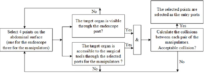
A simple workflow of the decision-aid system for finding the optimal ports’ position is shown in Figure 2.5. The process begins with selecting four preliminary points (ports) on the patient’s abdominal surface, three for the robot manipulators’ entry ports and one for the endoscope arm. The next step is to verify the accessibility of the target organ by the surgical tools through the preliminary ports. Similarly, the selected port for the endoscope arm should provide a complete vision of the target organ area for the endoscope. Other criteria such as the manipulators’ dexterity for manipulating the surgical tools through the selected ports on the patient’s abdominal surface can be added to the evaluation system. Moreover, the three selected ports for the manipulators should minimize the collision between each pair of the manipulators inside the patient (common area between the two manipulators’ working volumes in Figure 2.4).
Figure 2.5 Working flow for selecting the ports in a laparoscopic procedure
To summarize the workflow in Figure 2.5 we used three different criteria for checking the goodness/suitability of the points to be selected as the entry ports: the target organ accessibility, the visibility of the target organ, and the collision between the surgical tools inside the patient. However, we need to quantify these criteria in mathematical terms to find the optimal position of the ports on the patient’s
abdominal surface. The mathematical representation of the patient’s abdominal surface is a virtual 3D model of the inflated abdomen in the operating room, called the patient-specific model. The coordinates of the points on the patient’s abdominal surface can be found from the patient-specific model.
The robot is mathematically represented by a kinematic model in which the possible position and configuration of the manipulators—for bringing the manipulator endpoint (end-effector) to a certain position on the abdominal surface—is represented by the links and the joints angles.
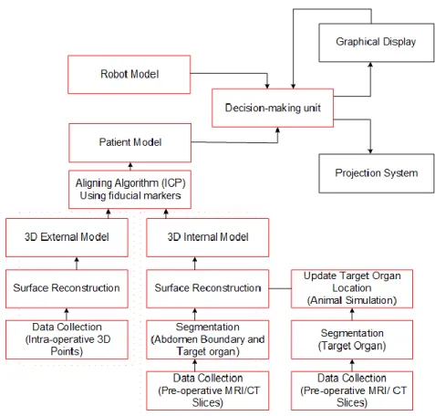
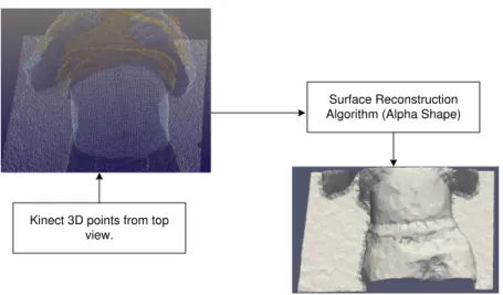
Figure 2.6 presents a schematic of our comprehensive decision-aid system in the port placement problem. The system has three main components: the robot model, the patient model and the decision-making unit. The patient model must contain the target organ and the external shape of the abdominal surface after insufflation. The patient model can be made directly from the medical images that are captured from the abdominal cavity under IAP. However, the operating room is usually too small to use medical imaging scanners (such as computed tomography (CT) or magnetic resonance imaging (MRI)) and the robotic system simultaneously. Instead, in this dissertation we use a range imaging camera (e.g. Kinect V2, Microsoft [36]) to image the external shape of the patient’s abdomen after insufflation. The captured image from the abdominal surface is a cloud of 3D points that is given to a surface reconstruction algorithm (alpha shape method) to generate a 3D mesh of the inflated abdomen, called the external model. The external model is not a complete patient model since it does not contain the target organ. Therefore, the next step of creating a patient model is to place the target organ inside the external model.
Figure 2.6 The proposed plan for planning ports in a laparoscopic surgery
We use pre-operative medical CT scans for finding the target organ’s shape and position in the patient’s body. The idea is to create another 3D model of the patient before the operation which includes the target organ, called the internal model. The internal model is aligned with the external model to place the target organ within the external model, and the result of the alignment is the patient-specific model. However, the original position of the target organ in the internal model is altered due to insufflation and, consequently, needs to be updated in the patient model under IAP.
To update the position of the target organ inside the patient model, we need to measure the shift of the target organs under IAP conditions in laparoscopic procedures. We used four pigs under same conditions to measure the organs’ displacement due to insufflation. The estimated shift of the organs in the pigs’ bodies is considered for similar organs in the human body, so we can correct the position of the target organ in the human’s body due to insufflation. In this dissertation, we focused on the hysterectomy procedure, in which the uterus is the target organ.
The next component of the decision-aid system is the robot model. The da Vinci SI (Intuitive) robot consists of three manipulators and one endoscope arm (Figure 2.2). From the robot model, we can determine the position of the manipulators’ end-effectors relative to the patient’s position in the operating room. In fact, having the patient and the robot models in the decision-aid system, the manipulators’ end-effectors’
position relative to the patient’s body, and the coordinates of the points on the patient’s body are the known parameters in the decision-making unit in Figure 2.6. The decision-making unit is responsible for performing two major tasks: first checking the accessibility of the points on the patient’s model (respect to the target organ position) to each of the robot arms and selecting and marking the accessible areas on the patient model. After finding the accessible areas for the manipulators, the second task of the decision-making unit is to use an optimization algorithm to minimize the collision risk between each pair of the manipulators inside the patient model. The output of the optimization algorithm is the optimal locations of the ports on the patient model that can be either projected on the patient’s abdominal surface or displayed on a monitor in the operating room.
The second goal of this dissertation is to reduce the pre-operative planning and set-up time in our port placement solution. We can eliminate the need for making the internal model if we have enough knowledge about the target organ’s shape and position. We constructed the patient models for seven patients (who underwent a hysterectomy procedure) to estimate the position and the volume of the operation area inside the patient. As a result, having only the external model, we will able to predict the target organ position inside the patient after insufflation without constructing the internal model.
The final goal of the project is to validate our port placement system by verifying its performance in determining the optimal locations of the ports on the patients’ abdominal surface. We use a body phantom (including a target organ) with known optimal locations of the ports that were obtained from previous surgical procedures. We use our port placement system to determine the optimal locations of the ports on the phantom surface and compare them with the actual ports’ location from the surgical procedures.
2.3 Chapter Summary
In this chapter, we reviewed several background items that provide context for the port placement problem in the dissertation. This includes a short description about MIS procedures and the port placement difficulties in robotic surgery. We also briefly described the goals of our research in the dissertation, which include a comprehensive solution to the port placement problem in the hysterectomy procedure. Finally, we introduced the main components of our port placement system (the patient model, the robot model, and the decision-making unit) that are discussed with more details in subsequent chapters.
Chapter 3
General Approach (Methodology)
In this chapter we will introduce our methodology to solve the port placement problem in hysterectomy procedures. This methodology is applicable to other laparoscopic procedures in the abdominal or pelvic areas (such as prostatectomy). Based on the project workflow in Figure 2.6, our design of the port placement system includes three main components: a patient-specific model, a kinematic model of the robot manipulators (da Vinci SI), and an optimization algorithm.
The patient model is a 3D mesh that is constructed from 3D images of the patient’s abdominal surface—a range imaging camera (3D scanner) is used for imaging the inflated abdominal surface in the operating room. This patient model, called the external 3D model, does not include the target organ and the diseased areas inside the patient. Thus, we first need to make a 3D shape of the target organ, and then put it inside the external model. We will use image processing segmentation techniques to extract the shape of the target organ and the patient’s body shape from pre-operative 2D medical images. Using the segmented images and a surface reconstruction algorithm (alpha shape), another 3D model of the patient is constructed that contains the target organ, called the internal model.
The target organ is placed inside the external model by superimposing the external model on the internal model. However, these two models are not aligned well, because the external model is constructed after insufflation, whereas the internal model is built from the patient’s abdominal surface prior to insufflation. We will find a transformation matrix for aligning the internal and the external models, using four points on the patient’s body that are assumed to be fixed during insufflation.
The result of the alignment is the patient-specific model that contains the target organ. The abdominal surface in the patient model represents the patient’s abdomen after insufflation, however, the target organ’s position is changed in the patient model under IAP. To update the target organ’s position in the patient model, we will measure the shift of abdominal organs in the animals’ body due to insufflation (see subsection 3.4). The measured shift of the abdominal organs in the animals’ body is used for estimating the shift of similar organs in the human body (patient model) under IAP.
After completing the patient model (the 3D model of the inflated abdomen with the updated location of the target organ), we simulated the robot arms docking on the patient. The robot arms’ configuration, and the positions of the arms’ end-points relative to the patient’s body (patient model), are demonstrated by a robot model (see subsection 3.2).
Using the generated patient model and the robot model, we will introduce an optimization algorithm (section 3.4) for finding the optimal locations of the entry ports on the patient’s abdomen (patient model). This optimization algorithm minimizes possible collisions between the manipulators, and maximizes an efficiency index that is defined as the ratio of the volume of the manipulation and the volume of the endoscope view.
3.1 Patient-Specific Model
The patient-specific model is a 3D mesh representation of the patient’s abdominal surface in the operating room. There are two ways to create a patient-specific model after insufflation: the intra-operative method and the combined technique. The idea in the intra-operative method is to scan the patient’s abdominal cavity after insufflation in the operating room. The captured 2D scans of the patient’s body are used to generate two 3D meshes of the patient’s abdomen and the target organ (see section 3.1.2 for more details). The main drawback of this method (in robotic surgery) is the scanning difficulties in the operating room. The operating room is usually too limited a space to use MRI/CT scanners and the robot simultaneously. MR scanners are too bulky to be used during robotic surgery, so the patient needs to be moved for the image acquisition. Also, using advanced portable CT scanners (e.g. mobile C-arm) is an expensive and complex procedure for making a patient 3D model in the operating room [37, 38].
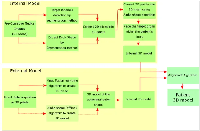
In the combined method, we create two different 3D models of the patient’s abdominal cavity before and after insufflation. These two models are called internal and external model respectively. The work flow for constructing the internal and the external models is illustrated in Figure 3.1.
Unlike the patient’s intra-operative model, the internal model is constructed from pre-operative medical images, and it contains the target organ which is extracted (segmented) from the images and placed in the internal model. However, the abdominal surface and the target organ’s shape and location are changed
after insufflation. This means that the outer shape of the abdomen and the target organ’s position in the internal model need to be updated after insufflation. To update the outer shape of the abdomen after insufflation, we image the abdominal surface in the operating room by using a 3D scanner or a range imaging camera in the operating room. The 3D scanner generates a depth (3D) image of the patient’s abdomen after insufflation, called the external model—we used the Kinect V2 camera (Microsoft [36]) for imaging the patient’s body in the operating room as shown in Figure 3.2.
Figure 3.1 Workflow to construct the patient-specific model in “combined” method
Figure 3.2 Experimental set-up to capture 3D points from the abdominal surface in the operating room
Operating Table

![Figure 2.3 Left: Four degrees of freedom at the entry port (three rotations and one translation) Right: da Vinci Endo-Wrist design of the surgical tool tip [2].](https://thumb-eu.123doks.com/thumbv2/123doknet/7891951.264269/23.918.171.750.105.339/figure-degrees-freedom-rotations-translation-right-vinci-surgical.webp)

![Figure 3.14 The corresponding points on the surface of two 3D objects (Stanford Bunny [52])](https://thumb-eu.123doks.com/thumbv2/123doknet/7891951.264269/51.918.237.678.251.469/figure-corresponding-points-surface-d-objects-stanford-bunny.webp)