HAL Id: hal-00460916
https://hal.archives-ouvertes.fr/hal-00460916
Submitted on 2 Mar 2010HAL is a multi-disciplinary open access archive for the deposit and dissemination of sci-entific research documents, whether they are pub-lished or not. The documents may come from teaching and research institutions in France or abroad, or from public or private research centers.
L’archive ouverte pluridisciplinaire HAL, est destinée au dépôt et à la diffusion de documents scientifiques de niveau recherche, publiés ou non, émanant des établissements d’enseignement et de recherche français ou étrangers, des laboratoires publics ou privés.
Lyotropic Lamellar Phase Doped with a Nematic Phase
of Magnetic Nanorods
Doru Constantin, Patrick Davidson, Corinne Chanéac
To cite this version:
Doru Constantin, Patrick Davidson, Corinne Chanéac. Lyotropic Lamellar Phase Doped with a Nematic Phase of Magnetic Nanorods. Langmuir, American Chemical Society, 2010, 26 (7), pp.4586-4589. �10.1021/la100045r�. �hal-00460916�
Lyotropic lamellar phase doped with a nematic
phase of magnetic nanorods
Doru Constantin,
∗,†Patrick Davidson,
†and Corinne Chanéac
‡Laboratoire de Physique des Solides, Université Paris-Sud, CNRS, UMR8502, 91405 Orsay, France., and Laboratoire de Chimie de la Matière Condensée, Université Paris VI, CNRS,
UMR7574, 75252 Paris, France.
E-mail: constantin@lps.u-psud.fr
Abstract
We report the elaboration of a hybrid mesophase combining the lamellar order of a lyotropic sys-tem of nonionic surfactant and the nematic order of a concentrated solution of inorganic nanorods confined between the surfactant layers. Highly aligned samples of this mesophase can be obtained by thermal annealing, and the orientation of the nanorods is readily controlled with a magnetic field. High-resolution synchrotron x-ray scatter-ing and polarised optical microscopy show that, compared to their isolated counterparts, both the nematic and lamellar orders are altered, demon-strating their interplay.
∗To whom correspondence should be addressed
†Laboratoire de Physique des Solides, Université
Paris-Sud, CNRS, UMR8502, 91405 Orsay, France.
‡Laboratoire de Chimie de la Matière Condensée,
Uni-versité Paris VI, CNRS, UMR7574, 75252 Paris, France.
Hybrid soft-matter systems, combining at the nanometric scale two components with different types of order, have recently been the focus of a fast-increasing body of research. Indeed, such sys-tems raise interesting fundamental questions about the interaction of the different kinds of order in-volved and also offer new perspectives of applica-tions, for example in drug delivery.1
In particular, lamellar phases doped with anisotropic inclusions received sustained attention since their experimental realization in DNA/lipid complexes.2,3 Since then, various other organic dopants have been used, such as viruses4 and peptides.5 These experimental achievements also prompted extensive theoretical efforts,6–8 concen-trating on the interplay of the two types of order (the lamellar one of the matrix and that of the in-clusions within it), and on the characteristics of a possible 2D-smectic phase formed by the inclu-sions.
These systems are generally obtained by elec-trostatic complexation through a precipitation pro-cess; as such, their texture is very hard to control and they usually occur in the form of multilay-ered globules with random orientation. It is there-fore difficult to discriminate between their molec-ular organization in the plane of the layers and that along the director of the phase. Furthermore, they are quite concentrated (lamellar spacings of a few nm), which severely restricts the size of the inclusions.
In this Letter, we present a new hybrid system, consisting of a dilute lamellar phase (formed by a
nonionic surfactant) doped with a nematic phase of inorganic goethite (α− FeOOH) nanorods that differ from the organic dopants used so far by their magnetic properties. The resulting composite (ne-matic/lamellar) phase is very fluid, and hence eas-ily aligned, which allowed us to study its structure in detail. A notable advantage is that the orienta-tion of the nanorods can be controlled by an exter-nally applied magnetic field of moderate strength.
The degree of order of each component (quanti-fied by the width of the Bragg peak for the lamel-lar host phase and by the nematic order parame-ter for the confined nanorods) changes due to the presence of the other component, confirming their intimate interaction.
Furthermore, this system shows promise as tem-plate for the production of hybrid materials, e.g. for magnetic storage applications,9 shielding,10 metamaterials11 etc.
The matrix is the C12EO5/hexanol/H2O system,
where C12EO5 stands for the nonionic surfactant
penta(ethylene glycol) monododecyl ether. Its lamellar phase can be diluted down to spacings d in the micron range, while the bilayer thickness
δ ≈ 2.9 nm.12,13 We used a hexanol/C12EO5ratio
of 0.33 by weight, corresponding to a molar ra-tio of 1.3 (hexanol molecules for each surfactant molecule). The main role of hexanol is to bring the lamellar phase domain down to room temper-ature. The surfactant was acquired from Nikko and the 1–hexanol from Fluka; they were used without further purification. For all the samples discussed in this paper, the fraction of membrane
φm= (VC12EO5+Vhexanol)/Vtotal= 6.26 vol %.
Goethite (α− FeOOH) is widely used as a pig-ment of ochre color.14 In bulk, its density isρg= 4.37 g/cm3. The nanorods were synthesized
ac-cording to well-established protocols.15,16 Stable aqueous suspensions of non-aggregated goethite nanorods are obtained by repeated centrifugation and dispersion in water up to pH = 3, where
their surface is hydroxylated, with a surface charge of 0.2 C m−2 (the isoelectric point corresponds to
pH= 9). Although bulk goethite is
antiferromag-netic, the nanorods bear a permanent magnetic dipole µ ∼ 1200µB along their long axis, prob-ably due to uncompensated surface spins (with
µB= 9.274 10−24J/T the Bohr magneton). There-fore, in suspension, the nanorods are easily aligned
parallel to a small magnetic field. Furthermore, the easy magnetisation axis is perpendicular to this di-rection so that, at high applied fields, the induced magnetic moment overtakes the permanent one and the orientation of the rods switches to perpen-dicular to the field at a critical value B ∼ 350 mT.17 When the rods are confined within the lamellar phase, the reorientation also occurs, at the same field value, and the texture of the lamellar phase follows the orientation of the rods.18
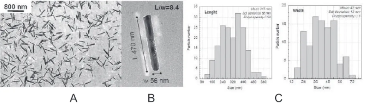
TEM observations were made on deposits of one drop of dilute nanoparticle suspension on a cop-per grid covered with a carbon membrane. The morphology is typical for a goethite crystal, elon-gated along the [001] direction and terminated by {210} faces14 with an aspect ratio of 8.4. The particle size distribution was determined over a population of 200 particles. The average length is ¯L = 315 nm and the standard deviation σL = 88 nm. For the transverse dimension, ¯D= 42 nm
and σD = 12 nm. The polydispersities are rela-tively low, σL/ ¯L = 0.28 and σD/ ¯D= 0.3. More precisely, the particles are lath-shaped and from powder X-ray diffraction line-broadening we infer that they have a mean width of 38 nm and a mean thickness of 18 nm, in good agreement with the TEM results.
Small angle x-ray scattering (SAXS) experi-ments were performed at the ID02 station of the European Synchrotron Radiation Facility syn-chrotron in Grenoble, France. The incident beam had a wavelengthλ = 0.0995 nm, and the sample–
detector distance was 5 m. The scattered x-rays were detected with a specially developed CCD camera. A detailed description of the experimen-tal setup can be found in reference 19. The q range over which the data could be reliably collected was 0.02 < q < 0.6 nm−1. The samples were held in
flat glass capillaries, 50 µm thick and 1 mm wide (Vitrocom, NJ, USA). The flat faces of the cap-illaries were set perpendicular to the x-ray beam. The magnetic field was applied using a motorized variable-gap setup available at the beamline.
To determine the order parameter of the ne-matic phase, azimuthal sections I(θ) through the
scattered signal at the radial position qmax = 2π/(80 nm) of the nematic peak were fitted with
a profile derived from the Maier-Saupe theory, as discussed in detail in references 20–22.
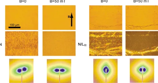
Figure 1: Optical microscopy textures (top) and SAXS signal (bottom) of the nematic phase of goethite, at a concentrationφg= 8 vol %, in water (left) and contained within the lamellar Lα phase (right). The lower microscopy images are taken between crossed polarizers, parallel to the image sides. In both cases, the nematic phase is very well aligned along the magnetic field, even at a relatively weak value of 50 mT. In the panel on the right, the lamellar phase is almost completely aligned in homeotropic anchoring (bilayers parallel to the flat faces of the capillary), with the exception of a few oily streak defects, visible in the microscopy images and which give rise to the very weak and sharp peaks along the vertical axis in the SAXS images.
Microscopy observations were done using an Olympus BX51 microscope (at 5×–40× magni-fication) using linearly polarized light and, when specified, an analyzer perpendicular to the incident polarization. For birefringence measurements we used a Berek compensator (U-CBE from Olym-pus) and a green band-pass filter (480–580 nm.) The magnetic field was applied using a home-made setup based on permanent magnets with a variable gap. One can thus reach field intensities of up to 0.9 T.
Figure 1 presents a comparison between an aqueous nematic suspension N of goethite nanorods (left) and the hybrid nematic/lamellar (N/Lα) mesophase (right), with and without an applied magnetic field. For the N/Lα system, in the absence of a magnetic field, the texture of the phase as observed between crossed polarizers (middle row) exhibits both the oily-streak defects due to the smectic symmetry of the lamellar com-ponent and textures typical for a nematic phase (in-between the oily streaks). Applying a modest (50 mT) magnetic field aligns the nematic com-ponent, so that only the lamellar defects remain visible.
Using SAXS, we studied the orientation of the
goethite nanorods confined in the N/Lα phase. The SAXS patterns (Figure 1, bottom row) show that the confined nanorods are easily aligned along the magnetic field direction, without disrupting the texture of the lamellar phase. The particles re-main aligned when the magnetic field is switched off, showing that the nematic uniform alignment of the confined nanorods is stable. Moreover, we measured by SAXS the order parameter S in the
N and N/Lα phases at the same particle
concen-tration φg = 8 vol %, on samples aligned using a moderate magnetic field (50–200 mT). While the aqueous nematic phase N has S ≃ 0.75, the hybrid system exhibits lower nematic order, with
S ≃ 0.45 (Figure 2A). This decrease could be due
to the weakness of orientational correlations be-tween the particles confined bebe-tween different sur-factant bilayers. Above the reorientation thresh-old, the order parameter of the rods varies con-tinuously and reaches saturation at about 700 mT (Figure 2A). No significant effect was observed above this value. Also, the magnetic field has no detectable effect on the undoped lamellar phase, even at the highest field values we could reach.
Another noteworthy characteristic of the hy-brid system is the enhanced susceptibility of the
-0.4 -0.2 0.0 0.2 S 1000 800 600 400 200 0 B [mT] Isotropic phase 1.0 0.8 0.6 0.4 0.2 0.0 -0.2 -0.4 S 1000 800 600 400 200 0 B [mT] Nematic phase fg= 8 % N/La N -10 -5 0 5 Dn [10 -3 ] 600 400 200 0 B [mT] fg = 3.50 % I/La I Coexistence (total fg= 6.61 %) I/La I A B C
Figure 2: A – Order parameter S (calculated from the SAXS patterns) of the nematic phase of goethite nanorods, in the lamellar phase (N) and in water (▽) as a function of the applied magnetic field. At field
values B& 350 mT the nanorods align perpendicular to the field, resulting in negative values of the order
parameter. B – Induced order parameter and C – induced birefringence of the isotropic phase of goethite nanorods as a function of the applied magnetic field, for two concentrationsφg. The symbols are the same in subfigures B and C. The optical birefringence measurements cannot be performed in the lamellar phase above the reorientation field value due to the change in texture (homeotropic to planar).
isotropic confined particle phase (I/Lα), quanti-fied by the induced order parameter S(B)
(Fig-ure 2B) and birefringence∆n(B) (Figure 2C)
un-der an applied magnetic field B. The experiments were performed for two different goethite con-centrations, φg = 3.5 vol % and at coexistence with the N/Lα phase, at an overall concentration
φg= 6.61 vol %. Due to the presence of the lamel-lar phase, we were not able to determine precisely the goethite content in the two coexisting phases, but it appears to be roughly similar to that in aque-ous solutions (approx. 4.5 : 7.5 vol %).
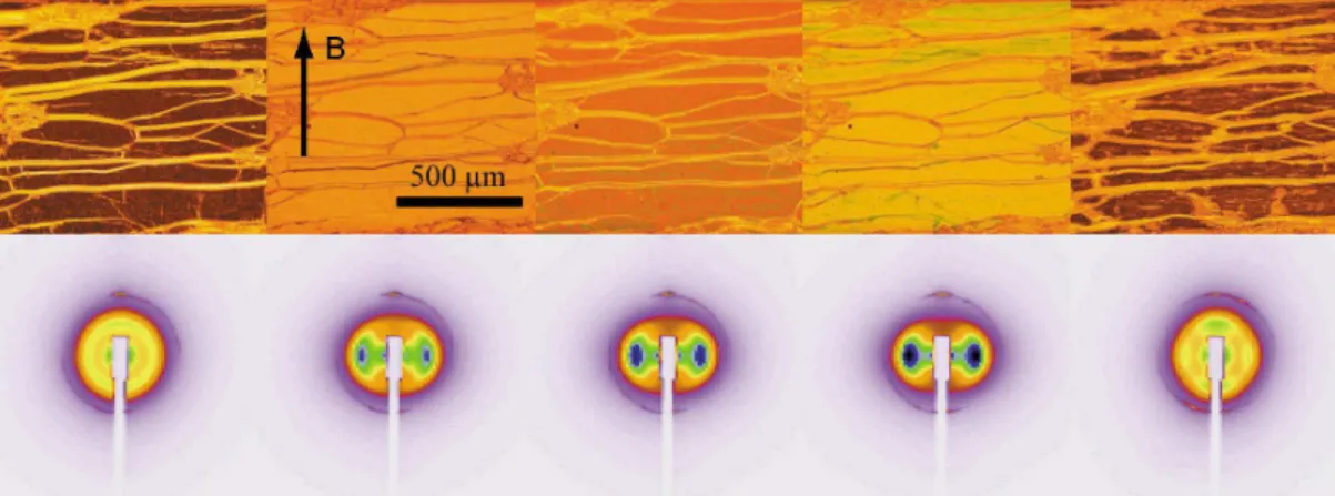
Both parameters are clearly higher in the hy-brid system. This feature is extremely strong for the field-induced birefringence (diamonds in Figure 2C) of a confined isotropic phase of vol-ume fraction φg= 6.61 vol %, within the bipha-sic domain of aqueous goethite suspensions. At this concentration, there is coexistence between the isotropic- and nematic-doped lamellar phases (I/Lα and N/Lα), which were identified optically, within the same capillary, by their distinct textures. The gap between 33 and 350 mT corresponds to birefringence values that cannot be reliably deter-mined using our setup. The corresponding mi-croscopy and SAXS images are shown in Figure 3, where the strong birefringence is revealed by the color shift and the progressively increasing order parameter of the nanorods by the horizontal lobes
in the scattering pattern.
Both the lower order parameter in the nematic phase and the higher susceptibility in the isotropic phase are compatible with a second-order phase transition (predicted in the literature for a 2D ne-matic phase23,24), as opposed to the first-order transition in the aqueous system.17
Finally, the presence of the inclusions affects the structure of the host lamellar phase, which be-comes stiffer, as seen by the decreasing width of the Bragg peak with increasing goethite concen-tration. This effect is displayed in Figure 4. We can tentatively attribute it to a strong interaction between the nanorods and the surfactant bilayers, leading to the formation of hydrogen bonds.25The nanorods are thus adsorbed onto the bilayers and increase their stiffness.
We emphasize that the two components (the sur-factant layers and the nanorods) are intimately mixed. While the lamellar order is of course im-posed by the surfactant bilayers, it also applies to the nanorods confined between these bilayers. As a result, there is only one repeat distance, giving rise to the single set of Bragg peaks, discussed in Figure 4.
It is noteworthy that the overall X-ray signal is mainly due to the nanorods (at this dilution, the contribution of the surfactant bilayers is negligi-ble). Indeed, the structure factors are obtained
di-Figure 3: Optical microscopy textures (top) and SAXS signal (bottom) of the lamellar Lα phase doped with the goethite isotropic phase (I/Lα) at coexistence with the nematic-doped phase N/Lα for different values of the applied field. The microscopy images are taken between crossed polarizers, parallel to the image sides. From left to right, the field values are: B= 0, 27, 52.5, 104 and 370 mT.
viding the measured intensity by the form factor of the nanorods.26 No peak can be detected for goethite concentrationsφg< 2 vol %.
The two components of the hybrid mesophase interact in non-trivial ways, as demonstrated by the enhanced magnetic field susceptibility of the nanorods (Figure 2, B and C) and by the in-creased stiffness of the lamellar phase (Figure 4). For the most concentrated system, the nanorods exhibit both nematic order (also encountered in aqueous solutions) and a lamellar order imposed by the confining surfactant bilayers. In this re-spect, the phase is similar to those encountered in complexes formed by DNA with cationic lipids, with the important distinction that we use a di-lute phase of nonionic surfactant, which is easily aligned by thermal treatment and that the orienta-tion of the nanorods couples to an external mag-netic field. As such, this hybrid phase could pro-vide an ideal testing ground for the hypothesized “sliding phases”,27 stacks of weakly-coupled lay-ers with a certain degree of two-dimensional (in-plane) order within the layers.
From a practical point of view, the combination of these two types of order makes the system a promising candidate for the formulation of com-posite materials with controlled periodicity and anisotropy, ordered over macroscopic distances. Moreover, the magnetic properties of the goethite nanorods are particularly interesting in this re-spect. 3.0 2.5 2.0 1.5 1.0 Struc ture facto r 0.14 0.12 0.10 0.08 qz [nm-1] 8.01 % 6.61 % 5.07 % 3.50 % 1.99 % φg 10 8 6 4 ∆ q [10 -3 nm -1 ] 8 6 4 2 0 φg [%] +2 +1 -1 -2 qz qy
A
B
C
Figure 4: A – SAXS image (taken without mag-netic field) of a lamellar phase containing φg = 6.61 vol % goethite, aligned in planar anchoring
(the layer normal is along z.) Several Bragg peaks are visible, labelled by their index. B – Structure factors of the lamellar phase doped with increas-ing amounts of goethite, indicated alongside the curves. The curves are shifted vertically in steps of 0.5. C – Width of the Bragg peaks in B as a function of the goethite concentration.
Acknowledgement The ESRF is acknowledged
for the provision of beamtime (experiment SC-2393, ID02 beamline). The authors thank P. Boesecke, M. Impéror, A. Poulos and B. Pansu for assistance with the synchrotron SAXS exper-iments and S. Rouzière for technical help.
References
(1) Ewert, K.; Slack, N. L.; Ahmad, A.; Evans, H. M.; Lin, A. J.; Samuel, C. E.; Safinya, C. R. Current Medicinal Chemistry
2004,11,133-149.
(2) Rädler, J. O.; Koltover, I.; Salditt, T.; Safinya, C. R. Science 1997,275,810-814. (3) Koltover, I.; Salditt, T.; Rädler, J. O.;
Safinya, C. R. Science 1998,281,78-81. (4) Yang, L.; Liang, H.; Angelini, T. E.;
But-ler, J.; Coridan, R.; Tang, J. X.; Wong, G. C. L. Nature Materials 2004,3,615-619. (5) Koltover, I.; Sahu, S.; Davis, N. Angew.
Chem. 2004,116, 4126-4129.
(6) Salditt, T.; Koltover, I.; Rädler, J. O.; Safinya, C. R. Phys. Rev. Lett. 1997, 79,
2582-2585.
(7) Goluboviˇc, L.; Goluboviˇc, M. Phys. Rev.
Lett. 1998,80,4341-4344.
(8) O’Hern, C. S.; Lubensky, T. C. Phys. Rev.
Lett. 1998,80,4345-4348.
(9) Sun, S.; Murray, C. B.; Weller, D.; Folks, L.; Moser, A. Science 2000, 287,
1989-1992.
(10) Gass, J.; Poddar, P.; Almand, J.; Srinath, S.; Srikanth, H. Adv. Funct. Mater. 2006,16, 71-75.
(11) Shelby, R. A.; Smith, D. R.; Schultz, S.
Sci-ence 2001,292,77-79.
(12) Freyssingeas, E.; Nallet, F.; Roux, D.
Lang-muir 1996,12,6028-6035.
(13) Freyssingeas, E.; Roux, D.; Nallet, F. J.
Phys. II (France) 1997,7,913-929.
(14) Cornell, R. M.; Schwertmann, U. The iron
oxides, structure, properties, reactions, oc-currence and uses; VCH: Weinheim, 1996.
(15) Atkinson, R. J.; Posner, A. M.; Quirk, J. P.
J. Phys. Chem. 1967,71,550-558.
(16) Jolivet, J.-P.; Chanéac, C.; Tronc, E. Chem.
Commun. 2004, 481-487.
(17) Lemaire, B. J.; Davidson, P.; Ferré, J.; Jamet, J. P.; Panine, P.; Dozov, I.; Jo-livet, J. P. Phys. Rev. Lett. 2002,88,125507. (18) Béneut, K.; Constantin, D.; Davidson, P.;
Dessombz, A.; Chanéac, C. Langmuir 2008,
24,8205-8209.
(19) Narayanan, T.; Diat, O.; Bosecke, P. Nucl.
Instrum. Methods Phys. Res. A 2001, 467,
1005-1009.
(20) Davidson, P.; Petermann, D.; Levelut, A. M.
J. Phys. II (France) 1995,5, 113-131.
(21) Lemaire, B. J.; Davidson, P.; Ferré, J.; Jamet, J. P.; Petermann, D.; Panine, P.; Do-zov, I.; Jolivet, J. P. Eur. Phys. J. E 2004,13,
291-308.
(22) Lemaire, B. J.; Davidson, P.; Petermann, D.; Panine, P.; Dozov, I.; Stoenescu, D.; Jo-livet, J. P. Eur. Phys. J. E 2004,13,309-319. (23) van der Schoot, P. J. Chem. Phys. 1997,106,
2355-2359.
(24) Wink, R. L. C. Phys. Rev. Lett. 2007, 98,
217801.
(25) Frost, R.; Zhu, H. Y.; Wu, P.; Bostrom, T.
Materials Letters 2005,59,2238-2241.
(26) The form factor was measured in a di-lute isotropic solution, so it corresponds to randomly oriented nanorods. However, for highly anisotropic particles and as long as the scattering vector is not too small, this is dom-inated by the transverse form factor of the particles.
(27) O’Hern, C. S.; Lubensky, T. C.; Toner, J.
Lyotropic lamellar phase doped with a nematic phase
of magnetic nanorods
–Supplementary Information–
Doru Constantin, Patrick Davidson and Corinne Chan´eac
Chemical
The goethite nanorods are formed by a dissolution-crystallization process from 2-line ferrihydrite, a poorly defined highly hydrated phase. 400 ml of a 0.1 M aqueous solution of Fe(NO3)3 were hydrolysed by addition of base solution (NaOH, 1M) at pH=11 and
room temperature, leading to a brown precipitate. After ageing for 15 days, the solution is ochre in color and contains rod-shaped nanoparticles (see below for the size analysis). The solid is isolated by centrifugation and then dispersed in a 3M solution of nitric acid for 2 hours in order to charge the surface positively. Stable aqueous suspensions of non-aggregated goethite nanorods are obtained by repeated centrifugation of this mixture and dispersion in water up to pH=3.
Particle morphology: TEM analysis
Figure 1 presents a representative TEM image and the particle size distribution. The subsequent analysis was described in the text.
A B C
Figure 1: TEM image showing a large quantity of non-aggregated nanorods (A), Zoom on one acicular goethite crystal with typical dimensions (length and width) and an aspect ratio of 8.4 (B), length and width distributions obtained from measurements over 200 particles (C).
Formulation
The volume fractions φm and φg are defined with respect to the total volume of the
solution. The mass concentrations are determined directly by weighing the components 1
into vials and the volume concentrations are then calculated using: ρC12EO5 = 0.95 g/cm3,
ρhex = 0.82 g/cm3, and ρgoeth = 4.37 g/cm3.
Two stock solutions were used, one a concentrated lamellar phase with φm = 62.82%
(and with mhex/mC12EO5 = 0.35) and no goethite, and the other with φg = 9% and
no surfactant. Mixing the appropriate amounts of these stock solutions and diluting with a 10−3M HNO
3 solution (to maintain a constant pH = 3) yielded the desired final
concentrations of membrane and goethite. We assumed that all the hexanol remains in the membrane, since its water solubility is low.
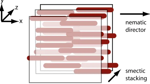
Schematic of the hybrid phase
depicts the hybrid phase. The surfactant membranes are perpendicular to the z direction (so the Bragg peaks appear along the qz axis, as shown in Figure 4A of the main text)
and the nanorods are confined in the (x, y) plane. For the nematic case, they are also oriented (on the average) along the x axis.
x
y
z
nematic
director
smectic
stacking
Figure 2: Representation of the hybrid phase. Three surfactant membranes are shown, as well as the two intermediate layers of nanorods.