This is an author-deposited version published in:
http://oatao.univ-toulouse.fr/
Eprints ID: 13650
To link to this article: DOI:10.1103/PhysRevE.91.031001
URL: http://dx.doi.org/10.1103/PhysRevE.91.031001
To cite this version:
Jardin, Thierry and David, Laurent Coriolis effects
enhance lift on revolving wings. (2015) Physical Review E. pp. 1-4. ISSN
1539-3755
O
pen
A
rchive
T
oulouse
A
rchive
O
uverte (
OATAO
)
OATAO is an open access repository that collects the work of Toulouse researchers and
makes it freely available over the web where possible.
Any correspondence concerning this service should be sent to the repository
administrator: [email protected]
RAPID COMMUNICATIONS
Coriolis effects enhance lift on revolving wings
T. Jardin1and L. David2
1Institut Sup´erieur de l’A´eronautique et de l’Espace, University of Toulouse, 10 Avenue Edouard-Belin, Toulouse 31055, France 2Institut Pprime, University of Poitiers, 11 Boulevard Marie et Pierre Curie, Futuroscope Chasseneuil 86962, France
At high angles of attack, an aircraft wing stalls. This dreaded event is characterized by the development of a leading edge vortex on the upper surface of the wing, followed by its shedding which causes a drastic drop in the aerodynamic lift. At similar angles of attack, the leading edge vortex on an insect wing or an autorotating seed membrane remains robustly attached, ensuring high sustained lift. What are the mechanisms responsible for both leading edge vortex attachment and high lift generation on revolving wings? We review the three main hypotheses that attempt to explain this specificity and, using direct numerical simulations of the Navier-Stokes equations, we show that the latter originates in Coriolis effects.
Much of the fascination of living creatures may well reside in the mystery behind their functioning, which despite con-siderable efforts scientists are mostly incapable of mimicking. Among the creatures that scientists are trying to mimic are dragonflies and hummingbirds. Because of their stunning flight agility, these species draw attention for the development of microair vehicles (MAVs). MAVs that emulate or even excel dragonflies in terms of flight agility would revolutionize the way we conduct missions of reconnaissance in constrained environments. But to mimic and outperform insects flight, one must first understand its origins.
How do insects fly? It is this question that keeps stirring up the debate in the scientific community and to which Ellington et al. provided a key answer in 1996 [1]. By visualizing the flow around a hawkmoth (Manduca sexta) model wing, the research team demonstrates that the lift generated by a revolving flapping wing is correlated to the development of an intense leading edge vortex (LEV) that remains robustly attached to the upper surface of the wing. At that time, this high-lift mechanism is new to conventional aerodynamics used to explain the flight of aircrafts, for example. On an aircraft wing, a LEV forms at high angles of attack but, conversely to that observed on a revolving wing, it is quickly shed into the wake causing a drastic drop in the aerodynamic lift. Recently, Lentink et al. [2] elegantly reveal that the robust attachment of the LEV is also responsible for the unexpected high lift generated by the autorotating seeds of maples.
These observations raise an underlying question. What are the mechanisms responsible for the robust attachment of the LEV, and hence for the high sustained lift generated by insects wings and autorotating seeds? Overall, three hypotheses emerge. The first hypothesis, by Birch and Dickinson [3], says that the downward flow induced by the tip vortex limits the growth of the leading-edge vortex and hence contributes to its attachment. However, experimental and numerical results by Ringuette et al. [4], Taira and Colonius [5], and Jardin et al. [6] suggest that this hypothesis is only valid for low aspect ratio wings, with a semispan not exceeding 1.5 times the wing chord. The second hypothesis is initially proposed by Ellington et al.[1]. It says that a spanwise flow, presumably induced by spanwise gradients in flow speed along the wing span and resulting spanwise pressure gradients, tends to drain vorticity out of the LEV core. The vorticity produced at the leading
edge is balanced and does not accumulate inside the LEV which would otherwise rapidly shed into the wake. Recently, Jardin and David [7] test this hypothesis by considering a wing embedded in a spanwise varying oncoming flow (rectilinear shear flow). The authors show that spanwise gradients in flow speed does tend to limit vortex growth via spanwise flow drainage but that this mechanism does not suffice in generating high sustained lift. Although its attachment is promoted, the LEV does not develop close enough to the wing surface to ensure high lift. The third hypothesis, introduced by Lentink and Dickinson [8], says that rotational accelerations (Euler, centrifugal, and Coriolis effects) are responsible for sustained LEV attachment. In light of the aforementioned studies, this last hypothesis remains the most credible hypothesis so far.
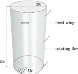
In this Rapid Communication, we test this last hypothesis. Toward that end, we solve the Navier-Stokes equations around a fixed finite wing embedded in a rotational shear flow (Fig.1). We compare four distinct cases that depend on whether or not we add source terms to modelize centrifugal and Coriolis effects in the Navier-Stokes equations [Eq. (1)]. These terms depend on the rotating speed imposed to the flow Ä, the radial distance from the wing root r, and the local fluid velocity u—recall that in Eq. (1), t is the time, p is the static pressure, and ρ and ν are the fluid density and viscosity, respectively. The four cases will henceforth be referred to as cases A, B, C, and D, respectively (TableI).
∂u ∂t +u∇u = − 1 ρ ∇p − Ä ×(Ä × r) | {z } centrifugal −2Ä × u | {z } Coriolis +ν.∇2u (1) The Navier-Stokes equations are directly solved using a finite volume method. The grid consists of five million polyhedral cells, with a typical grid spacing in all three dimensions of 0.02c in the vicinity of the wing. The time step is fixed to meet the Courant-Friedrichs-Lewy condition. Second order schemes are used for both spatial and temporal discretizations. The results presented are converged with respect to computation parameters (grid size, time step, and location of external boundary conditions). Furthermore, the approach has proven its ability to accurately predict the flow
FIG. 1. Illustration of the numerical setup. The fixed wing is modeled as a nonslip wall and embedded in a rotating (rigid body motion) flow. The latter is imposed via velocity Dirichlet conditions at the boundaries of the computational domain. The Navier-Stokes equations are directly solved in the fixed reference frame, taking into account additional centrifugal and/or Coriolis source terms.
past moving bodies [6] and, more generally, the occurrence of flow instabilities at low Reynolds numbers [9,10].
The wing profile is a 2.5% thickness flat plate with elliptic leading and trailing edges. The wing aspect ratio is set to AR = L/c =4, where L and c are the span and chord length, respectively. The wing angle of attack is fixed to α = 45◦
, far beyond the stall limit of the profile. The speed of the rotating flow is set to Ä × r on all boundary conditions, where Ä is a rotational speed and r is the radial distance from the wing root. The Reynolds number based on the wing chord c and the mean velocity along the wing span fV∞=ÄL/2 is fixed to
Re = fV∞c/ν =500.
In what follows, all data are nondimensionalized with respect to c and fV∞.
Figure 2 compares the lift coefficient CL as a function
of the nondimensional distance traveled by the wing δ for cases A (×), B (◦), C (+), and D (¤). We add the lift coefficient obtained for a wing embedded in a rectilinear shear flow (without source terms) and reproduced from Jardin and David [7]. In this particular case, referred to as case 0 (−), the spanwise gradient in flow speed is equal in magnitude to that imposed in cases A, B, C, and D but the flow is rectilinear rather than being rotational.
First, it can be observed from Fig.2that the lift coefficient obtained for case A (×) rapidly drops, beyond δ = 1. This
TABLE I. Definition of cases A, B, C, and D with respect to the introduction of centrifugal and Coriolis source terms in the Navier-Stokes equations.
Case Centrifugal term Coriolis term
A No No
B Yes No
C No Yes
D Yes Yes
trend is very similar to that observed in case 0 (−), which confirms that spanwise gradients in flow speed do not suffice in generating high sustained lift whether they are imposed via a rotational or rectilinear shear flow. In addition, this suggests that the rotational nature of the shear flow has a weak influence on lift generation when compared to the rectilinear shear flow case. Secondly, it is shown that the lift coefficient obtained for case B (◦) is very similar to that obtained for case A. In other words, centrifugal effects do not appear as an ultimate key mechanism in lift generation either. Conversely, the lift coefficient obtained for case C (+) demonstrates high levels in comparison to those observed for cases A and B. Therefore, it clearly appears that Coriolis effects play a significant role in the generation of high sustained lift on revolving wings. Finally, the lift coefficient obtained for case D (¤) is reduced in comparison to that obtained for case C. Here, centrifugal effects mitigate the influence of Coriolis effects on lift generation. A trend similar to that reported in the literature for revolving wings is hence recovered.
From this brief quantitative analysis, it clearly appears that Coriolis effects constitute a key element in lift generation on insect wings and autorotating seeds. What is yet to be understood is the influence of Coriolis effects on the flow structure and the attachment of the LEV. In other words, is there a strong correlation between Coriolis effects, LEV attachment, and high sustained lift?
Figure3displays Q-criterion isosurfaces obtained for cases A, B, C, and D at five distances of travel. Positive Q-criterion isosurfaces are here used as a means to identify vortex cores [11]. In all cases, at early stages (δ = 0.8), the LEV is coherent and exhibits a conical shape due to the spanwise gradients in flow speed: the LEV is fed vorticity more rapidly at the wing tip than at the wing root.
In case A, the LEV rapidly bursts into a noncoherent structure. This burst, referred to as global burst (as opposed to tip burst), is not visible in case 0 [7] which indicates the occurrence of an instability associated with rotational shear. Because of this instability, it is here delicate to conclude whether or not rotational shear promotes LEV attachment, as observed for rectilinear shear [7]. However, it is clear that rotational shear does not promote lift generation, which is very similar to that obtained in the case of rectilinear shear. Therefore, when compared to the rectilinear shear case, it appears that the global burst induced by the rotational shear has only a weak influence on lift generation. This observation ties in with the observations made by Harbig et al. [12]. In
RAPID COMMUNICATIONS
FIG. 3. Comparison of Q > 0 criterion isosurfaces obtained for cases A (first column), B (second column), C (third column), and D (fourth column) at five distances of travel δ = 0.8 (first row), 1.6 (second row), 2.4 (third row), 3.2 (fourth row), and 4 (fifth row).
their paper, the authors indicate that the aerodynamic loads generated by a flapping wing are weakly dependent on the occurrence of LEV burst in the outer portion of the wing (conclusions drawn for Reynolds numbers, based on the wing span and the velocity at the radius of gyration, above 3000). In other words, lift generation is not very sensitive to vortex burst, whether it is global or localized in the outer portion of the wing. In case B, the flow topology is very similar to that observed in case A. Centrifugal effects do not have a major impact on the development of the LEV, including the occurrence of global vortex burst. As previously mentioned, lift generation is thus unchanged with respect to case A.
Conversely, case C strongly differs from cases A and B. Here, Coriolis effects tend to stabilize the flow in that the global vortex burst induced by rotational shear is inhibited. However, a local vortex burst is now visible at the wing tip where the LEV and the tip vortex interact. Besides the global coherence recovery, the LEV is here robustly attached to the upper surface of the wing. In comparison to case A (and case 0) Coriolis effects tend to maintain the LEV close to the wing surface. This explains the high levels of lift observed in Fig.2. Coriolis effects are found to be mainly concentrated in the core and at the periphery of the LEV (Fig.4). This very localized action is promoted by local variations in velocity uassociated with the development of the LEV. In particular, streamwise flow acceleration above the LEV promotes the spanwise component of the Coriolis term while the spanwise component of u, induced by spanwise gradients in flow speed
FIG. 4. Contours of streamwise (left column) and spanwise (right column) components of the Coriolis term obtained for case C at midspan. Contours are superimposed to Q > 0 criterion isolines for three distances of travel δ = 0.8 (first row), 2.4 (second row), and 4 (third row).
[7], promotes the streamwise component of the Coriolis term. An interesting feature here is that the magnitude of the Coriolis term, hence its influence on LEV attachment, would not be so important without spanwise gradients in flow speed and the associated spanwise flow.
Finally, in case D, the flow topology is very similar to that observed in case C. This once again suggests that centrifugal effects only weakly impact the LEV development, even when coupled with Coriolis effects. However, a deeper analysis of the flow reveals that, although weak, modifications of the flow field (from cases C to D) are slightly enhanced with respect to those observed in the absence of Coriolis effects (from cases A to B). A glance at Eq. (1) suggests that small changes in flow velocity u induced by centrifugal effects are amplified through the term 2Ä × u when Coriolis effects are added. This may explain why a difference in lift generation is observed between case C and D, while no significant difference is found between case A and B. Overall, despite a very weak impact on LEV development, centrifugal effects mitigate the influence of Coriolis effects on lift generation.
By numerically playing with virtual worlds in which centrifugal and/or Coriolis effects may or may not be taken into account, we are able to evaluate the influence of the latter on the lift generated by revolving wings, such as insect wings or autorotating seeds. The results presented in this Rapid Communication show that Coriolis effects appear to be the key mechanism in lift generation, while centrifugal effects have a marginal impact. Furthermore, Coriolis effects are responsible for the attachment of the LEV close to the upper surface of the wing, demonstrating a strong correlation between high sustained lift and robust attachment of the LEV. Coriolis effects also tend to stabilize the rotating flow that would otherwise be subject to a rotational shear instability and trigger the global burst of the LEV. These results are in line with the conclusions reported by Lentink and Dickinson [8] and shed new light on the precise origin of high sustained lift generated by revolving wings.
[1] C. P. Ellington, C. van den Berg, A. P. Willmott and A. L. R. Thomas,Nature (London) 384,626(1996).
[2] D. Lentink, W. B. Dickson, J. L. van Leeuwen, and M. H. Dickinson,Science 324,1438(2009).
[3] J. M. Birch and M. H. Dickinson,Nature (London) 412,729
(2001).
[4] M. J. Ringuette, M. Milano, and M. Gharib,J. Fluid Mech. 581,
453(2007).
[5] K. Taira and T. Colonius,J. Fluid Mech. 623,187(2009).
[6] T. Jardin, A. Farcy, and L. David,J. Fluid Mech. 702,102(2012). [7] T. Jardin and L. David,Phys. Rev. E 90,013011(2014). [8] D. Lentink and M. H. Dickinson, J. Exp. Biol. 212, 2705
(2009).
[9] T. Jardin and Y. Bury,J. Fluid Mech. 696,285(2012). [10] Y. Bury and T. Jardin,Phys. Lett. A 376,3219(2012). [11] F. Hussain and J. Jeong,J. Fluid Mech. 285,69(1995). [12] R. R. Harbig, J. Sheridan, and M. C. Thompson,J. Fluid Mech.