PEOPLE'S DEMOCRATIC REPUBLIC OF ALGERIA
يملعلا ثحبلاو يلاعلا ميلعتلا ةرازو
MINISTRY OF HIGHER EDUCATION AND SCIENTIFIC RESEARCH
شابع ثاحرف تعماج
-فيطس
1
UNIVERSITY FERHAT ABBAS - SETIF 1
THESIS
Presented at Faculty of Technology Department of Electrical Engineering
For Obtaining Degree of
DOCTORATE OF SCIENCE
Option: Electrical PowerBy
Mr. KAMEL SALIM BELKHIR
Theme
Application Of Magnetic Power-Split Device / CVT To
Variable Speed Wind Turbine For Wind Power Generation
Defended on: 25/05/2014 Dissertation committee: Prof. M. N. HARMAS Chairman University Ferhat Abbas - Setif 1.
Prof. N. KHENFER Supervisor University Ferhat Abbas - Setif 1. Prof. T. REKIOUA Reviewer University Abdelrrahmane Mira, Bejaia.
Prof. S. DRID Reviewer University Hadj Lakhdar, Batna.
Dr. S. BARKAT Reviewer University of M'Sila.
Dr. M. HACHEMI Reviewer University Ferhat Abbas - Setif 1.
1
TABLE OF CONTENTS
ABSTRACT... 03 ACKNOWLEDGMENTS... 04 LIST OF TABLES... 05 LIST OF FIGURES... 06 NOMENCLATURE... 09 1. INTRODUCTION... 12 1.1 Background... 121.2 Power System Worries... 13
1.3 Purpose And Contributions... 14
1.4 Thesis Layout... 15
2. DIFFERENT WIND GENERATOR SYSTEMS... 16
2.1 Introduction... 16
2.2 Fixed Speed System... 17
2.3 Variable Speed Systems... 18
2.3.1 Limited Speed Concept... 19
2.3.2 Variable Speed Concept with Multiple-Stage Gearbox... 19
2.3.2.1 The Doubly Fed Induction Generator System... 20
2.3.2.2 Squirrel Cage Induction Generator System... 22
2.3.2.3 Permanent Magnetic Synchronous Generator System... 22
2.4 Variable Speed Direct-Drive Concept... 23
2.4.1 Electrically Excited Synchronous Generator... 24
2.4.2 Permanent Magnetic Synchronous Generator... 26
2.5 Variable Speed Concept With Single-Stage Gearbox... 26
2.6 Variable Speed Concept With Hydraulic Gearbox System... 27
2.7 Performance Comparisons... 28
2.8 Market Status... 30
2.9 Technology Trends... 32
2.10 Large Turbine Challenge... 33
2.11 Conclusion... 34
3. MAGNETIC POWER-SPLIT CONTINUOUSLY VARIABLE TRANSMISSION CVT... 35
2
3.1 Introduction... 35
3.2 Topologies Of Magnetic Gearbox... 36
3.3 Principle Of Operation... 37
3.3.1 Flux Density Waveforms... 38
3.3.2 Torque Transmission... 41
3.3.3 Cogging Torque... 42
3.3.4 Equation Of Motions... 43
3.4 Wind Energy Application... 44
3.4.1 Electromechanical Modelling... 44
3.5 Simulation Studies... 45
3.6 Conclusion... 49
4. 2.5 MW DIRECT-DRIVE MAGNETIC GEAR FOR WIND ENERGY... 50
4.1 Introduction... 50
4.2 Principle Operation... 50
4.3 Control Strategy... 54
4.3.1 Magnetic Gear Generator Side Control... 55
4.3.2 Grid-Side Control... 57
4.4 Simulation Results... 59
4.5 MPPT for Magnetic Gear Generator... 62
4.5.1 ANN Controlling Model... 63
4.5.2 The Structure Of MPPT Control... 64
4.5.3 Simulation Results... 65
4.6 Conclusion... 69
5. POWER-SPLIT MAGNETIC GEAR FOR WIND POWER... 70
5.1 Introduction... 70
5.2 Magnetic Gearbox... 70
5.3 Wind Turbine System With Proposed Magnetic Gear... 72
5.3.1 Magnetic Gear Controller... 73
5.3.2 Grid Side Control... 75
5.4 Simulation Results... 77 5.5 Conclusion... 82 6. CONCLUSION... 83 6.1 Summary... 83 6.2 Future Research... 84 7. BIBLIOGRAPHY... 85
3
For high power generation of future offshore wind turbine application, size and cost were the big challenge that must be overcome. Furthermore, the weight of lubrication system and the dimension of the mechanical gearbox must be taken into consideration. To overcome these problems, a new topology approach for wind power generation without mechanical gear is presented. Using magnetic gear coupled mechanically and magnetically with permanent magnet synchronous generator, even under low wind conditions often found inland, and without mechanical gear, the high speed can be reached with this topology. For these, two original ideas have been presented. The first one, deals with magnetic gear generator which contains two rotors, the input rotor and the output rotor. The mechanical energy extracted from the wind turbine is transferred to the input rotor, which is transmitted magnetically to the output rotor. The permanent magnet of the output rotor interacts with the stator windings to produce electromagnetic torque. Thus, the power captured by the wind turbine is transmitted to the grid by the stator winding.
The second idea is the use of power-split magnetic gear. The power transmitted to the grid is split between the generated power by the permanent magnetic synchronous generator and the power produced or consumed by the magnetic gear generator. Thus, the dimension of the nacelle will be reduced and the mechanical gear box can be reduced or omitted.
Computer simulation results are given to verify the validity of the proposed machine. It appears that the disadvantages associated to future offshore wind turbine can be surmounted using magnetic gear generator.
Key Words: Artificial neural network, magnetic gear, permanent magnet synchronous
4
The present research project and doctorate thesis was supported by Algeria's Ministry of Higher Education and Scientific Research and I am thankful.
I would like to express my deepest gratitude to my supervisor Professor Nabil Khenfer, for his advice, as well as to UK's Sheffield University and its Department of Electronics and Electrical Engineering; special thanks to Professor Dave Howe of the department's Electrical Machines and Drives Research Group who gave me the opportunity to work with his research group for fourteen months and to Ms Sara Gawthorpe for her administrative help and her kindness.
Many thanks to Professor Kais Attalah for his technical guidance and his intellectual skills during my research work. Working beside him was stimulating and his precious knowledge is quite amazing.
Professors Mohamed Naguib Harmas, Toufik Rekioua, Said Drid, Doctor Said Barkat and Doctor Mabrouk Hachemi did not hesitate a second to be members of the examining board for my thesis. I cannot but smile at them with acknowledgment.
My friend Kheirdine Difallah, alias Duke of Chestwood, naturalist and author, kindly reviewed the text using his good knowledge of the English language. May the Lord bless you Duke!
5
LIST OF TABLES
Table 2.1: Comparison of the direct-drive PMSG and
the fixed-speed SCIG concepts... 28
Table 2.2: Comparison of two 500 KW wind turbines with the direct-drive PMSG and fixed-speed SCIG system... 29
Table 2.3: Comparisons of five wind generator concept... 30
Table 2.4: Wind turbine concepts on the market over 2 MW... 31
Table 3.1: Parameters of magnetic gear... 38
Table 3.2: Parameters of magnetic gear... 47
Table 4.1: Parameters of magnetic gear generator... 59
6
LIST OF FIGURES
Figure 2.1: Fixed speed concept with SCIG generator... 17
Figure 2.2: Limited variable speed concept with WRIG... 19
Figure 2.3: Variable speed concept with DFIG... 21
Figure 2.4: Multiple-stage geared SCIG concept with full-scale converter... 22
Figure 2.5: Direct-drive PMSG concept... 24
Figure 2.6: Direct-drive EESG concept... 25
Figure 2.7: Single-stage drive PMSG with full-scale converter... 27
Figure 2.8: Hydraulic gearbox system... 28
Figure 2.9: World share of yearly installed power for different wind generator systems... 32
Figure 3.1: The magnetic gear. (a) Radial cross section. (b) Axial cross section... 36
Figure 3.2: Variation of radial flux density due to high speed rotor adjacent to low speed rotor... 38
Figure 3.3: Space harmonic spectrum of radial flux density due to high speed rotor adjacent to low speed rotor... 39
Figure 3.4: Variation of radial flux density due to low speed rotor adjacent to high speed rotor... 40
Figure 3.5: Space harmonic spectrum of radial flux density due to low speed rotor adjacent to high speed rotor... 41
Figure 3.6: Variation of maximum torque on high speed rotor... 42
Figure 3.7: Variation of maximum torque on low speed rotor... 42
Figure 3.8: Magnetic gear under variable speed... 44
Figure 3.9: A control scheme of magnetic gear... 45
Figure 3.10: Variable speed of the input rotor... 46
7
Figure 3.12: The output speed ωs... 47
Figure 3.13: The Controlling rotor ωh... 48
Figure 3.14: The torque of the output rotor Ts... 48
Figure 3.15: Torque of the input rotor Tl... 49
Figure 4.1: Magnetic gear generator.(a) Radial cross section. (b) Axial cross section... 51
Figure 4.2: Schematics of magnetic gears... 53
Figure 4.3: Standard step response of magnetic gear.(a) For 5.75 gear ratio. (b) For 13.5 gear ration. (c) For 15.5 gear ratio... 54
Figure 4.4: Magnetic gear generation topology... 55
Figure 4.5: Rotating reference frame... 56
Figure 4.6: General structure of MGG-side control... 57
Figure 4.7: Rotating reference frame... 58
Figure 4.8: General structure of grid side control... 59
Figure 4.9: The wind speed variation... 60
Figure 4.10: Torque of the magnetic gear generator (a) Torque of input rotor. (b) Torque of output rotor... 60
Figure 4.11: Rotors speed of the magnetic gear generator. (a) Input rotor. (b) Output rotor... 61
Figure 4.12: The dc-link voltage... 62
Figure 4.13: The power produced by magnetic gear generator... 62
Figure 4.14: Mechanical power versus rotor speed... 63
Figure 4.15: Training scheme using ANN controller... 64
Figure 4.16: Block diagram of the MPPT control system... 64
8 Figure 4.18: MPPT results under wind speed variation.
(a) The output of ANN controller. (b) Speed of the input rotor. (c) Speed of the output rotor. (d) dc-Link voltage.
(e) Output voltage of back-to-back converter. (f) Output voltage of filter.
(g) Mechanical turbine power. (h) Power injected to the grid... 68
Figure 5.1: Magnetic gear for wind turbine generator. (a) Radial cross section. (b) Axial cross section... 72
Figure 5.2: Wind turbine with a magnetic gear, permanent magnet synchronous generator and back-to-back converter... 73
Figure 5.3: Rotating reference frame... 74
Figure 5.4: General structure of magnetic gear controller... 75
Figure 5.5: Rotating reference frame... 76
Figure 5.6: General structure of control strategy... 77
Figure 5.7: The inner rotor speed variation... 78
Figure 5.8: The generator speed variation... 79
Figure 5.9: The variation of high rotor speed of magnetic gear... 79
Figure 5.10: The dc-link voltage... 80
Figure 5.11: The power transmitted to the inner rotor of the magnetic gear... 80
Figure 5.12: The power produces by the PMSG... 81
9
NOMENCLATURE
Symbols
A Swept area of rotor
Br Flux density
Cp Power coefficient
dq Park's reference frame
e Voltage at the output inverter Gr gear ratio
i Current
Jl Inertia of the input rotor Js Inertia of the output rotor Jh Inertia of the control rotor
L Inductance
LT Overall inductance of the grid-side converter ns Pole-pieces.
P Active power
p Pole-pairs
Ph Pole-pairs of high speed rotor
Pl Pole-pairs of low speed rotor Pt Wind turbine power
Q Reactive power
R Resistance
RT Overall resistance of the grid-side converter s Indicate the stator winding
Te Electromagnetic torque Tl Input torque
Tlo Load torque
Tmax Maximum torque which can be produced by the magnetic gear Tmec1, Tmec2 Mechanical torques
10
Ts Output torque
Tturbine Wind turbine torque
V Wind speed
v Stator voltage
v' grid voltage
ω Electrical angular velocity.
ωr Velocity of the permanent magnet ωh Velocity of the high speed rotor ωl Velocity of the low speed rotor
ωs Synchronous speed
ωs Velocity of ferromagnetic pole-pieces θl, Angular position of the input rotor θh Angular position of the control rotor θs Angular position of the output rotor
α Angle of attack
β Blade pitch angle
λ Tip speed ratio
φ Flux linkage
φPM Flux of the permanent magnet
ρ Air density
µr Permeability
Abbreviations
ANN Artificial neural network
CVT Continuously variable transmission DD Direct-drive
DFIG Doubly fed induction generator
EESG Electrically excited synchronous generator GWEC Global Wind Energy Council
MPPT Maximum power point tracking MGG Magnetic gear generator
11 PM Permanent magnetic
PMSG Permanent magnet synchronous generator SCIG Squirrel cage induction machine
SG Synchronous generator
WRIG Wound rotor induction generator
12
CHAPTER 1
INTRODUCTION
1.1. Background
The cost of electricity generated from wind turbines is no higher than that produced by fossil-fuel-generators. And there is good reason to think that the wind power will become a substantial source of electrical power throughout the world and could contribute to the reduction of CO2 emissions in the atmosphere [1].
International Greenpeace and the Global Wind Energy Council (GWEC) published their bi-annual report on the future of the wind industry. This shows that by the end of 2011, wind energy installations in the world would be raised to 240 GW, and that the industry is set to grow by at least another 40 GW in 2012. This means that wind power could supply up to 12% of the global electricity by the year 2020 [2].
Manufacturers have used a variety of generator concepts in their variable speed turbines. The doubly fed induction generator (DFIG), being the lightest, low-cost concepts and the rating of its power electronic converter is only 25-30% of the generator capacity, is used since 1990 and is still dominating the wind market. On the other hand, it needs a high-speed gearbox and extra maintenance. With the rapid development of wind turbine technologies, the future trends to the big size single wind turbine and to offshore wind energy [17]. This because turbine manufacturers have been looking for new directions. The permanent magnet synchronous generator (PMSG) concept seems to be the most promising [3].
Nowadays, the wind industry challenge is scaling up, cutting costs, and improving reliability. To fulfil that, some manufacturers replace the traditional gearboxes and high-speed generators with bigger low-speed generators which do not necessitate a geared transmission. Siemens company has begun selling a 3 MW turbine using direct-drive concept that replaces the conventional high-speed generator with a low-speed generator that eliminates the need for a gearbox [4].
13
Offshore wind turbine continues to be modest compared with onshore wind, with just 625 MW per annum between 2007 and 2011. This number has increased to just over 1 GW per year in the past two years. In parallel, the industry of onshore wind turbine has averaged over 30 GW globally in the same period. However, interest in the offshore sector continues to grow, with investors' commitments, policy support, and technological innovations [5].
Offshore wind is increasingly faced with pressure to deliver capacity on a large scale if it is able to reduce the costs in deeper waters. Installed offshore wind power capacity amounts to less than 2% of the total wind energy capacity installed worldwide. Currently, this amount reaches 4.62 GW, where offshore activations have become a regular and expanding contributor to wind power growth over the past decade. The share of offshore wind in Europe’s total wind additions peaked in 2010 at 9%, dropped off slightly in 2011 to 8%, and expected to jump to over 20% in 2012. The global offshore market is expected to reach 95 GW of installed wind energy capacity by 2025, which mean 13% of total global wind additions between 2012 and 2025 [5].
The wind turbine industry is continuously improving turbine designs to reduce the cost of wind energy. The most widely used method is to increase the power output of wind parks by increasing the power produced by each individual turbine. It is clear that by decreasing the number of machines per Mega-watt the operations and maintenance costs of the wind park could decrease [6].
1.2. Power System Worries
With rapid development of wind turbine technologies, the future of the wind turbine will be focused on huge single wind turbine to reduce the cost of placing wind turbine and offshore wind energy, due to higher wind speed and more space [6].
Bigger turbines reach higher in height above the earth's surface, where stronger winds blow. This allows them to extract more energy, and to work more efficiently. Using higher-capacity wind turbine reduces the number of turbines needed for a wind farm and results in dramatic reductions of the cost of wind energy [7].
Wind turbines have developed from an average of 700 kW to over 5 MW in the past decade. Due to reliable and efficient offshore wind energy, several offshore wind projects have been adopted. The offshore applications require lager turbine units, the sizes of wind
14
turbine is about 7 MW at the present time and the largest turbines of the near future would be about 20MW [8].
This virtual 20 MW design is still impossible to manufacture and is uneconomic. Its weight would be about 880 tonnes standing on top of a tower, which means that the plan it not feasible; the support structures could not carry such a big generator, the lubrication system and the huge mechanical gearbox, elevated up to 153 metres in height [9, 12].
1.3. Purpose and Contributions
By removing the mechanical gearbox and the lubrication system, we reduce the nacelle size and weight. To achieve this goal, we used magnetic gear power-split.
The high-torque magnetic gear was invented and demonstrated by Pr. K. Atallah, University of Sheffield, in 2001 [13]. It uses permanent magnets to transmit torque between an input and output shaft without mechanical contact.
The mechanical gearbox is used extensively to increase the rotational speed of wind power generators. It is usually more costly and weights more when we use a high-speed electrical machine together with a gearbox to transform speed and torque. Too, mechanical gearbox requires lubrication and cooling, while noise, vibration and reliability can be significant issues. Magnetic gears offer several potential advantages over mechanical gears. For instance, a reduced acoustic noise and vibration, reduced maintenance and improved reliability, a precise peak torque transmission capability and physical isolation between input and output shafts [14].
The topology and high performance of magnetic gear have been presented [1] and it has been shown that by using rare-earth magnets, a high torque density can be achieved [15].
To overcome dimension problems of the nacelle, this work illustrates two new topologies using a magnetic power-split to a variable speed wind turbine. In the first one is used a magnetic gear with two rotors and without mechanical gearbox, the rated power is transmitted to the grid via the magnetic gear [16]. In the second method is used a magnetic gear with three rotors, the power transmitted to the grid is split between the generator and the power produced or consumed by the magnetic gear.
15
1.4. Thesis Layout
The main purpose of this thesis is the analysis of the application of the magnetic continuously variable transmission (CVT) in variable wind speed. To use the magnetic power-split, both the control and the modeling of the system is significant. The main contribution of this thesis is to give two new wind generator concepts without mechanical gearbox. Details are as follows:
Chapter 2 illustrates overview of different wind generator systems with comparisons. Chapter 3 describes the design and the performance of a magnetic gear that employs rare-earth magnets. Chapter 4 presents the first new topologies using magnetic gear generator for wind energy, even under low wind conditions often found inland, and without mechanical gear. High speed can be reached using this concept. Chapter 5 presents the second concept, this uses power-split magnetic gear to variable speed wind turbine, the rated power transmitted to the grid is split between the permanent magnetic synchronous generator and the power produced or consumed by the power-split magnetic gear. Chapter 6 conclusion and future work are presented.
16
CHAPTER 2
DIFFERENT WIND GENERATOR
SYSTEMS
2.1. Introduction
As the use of wind power plants was increasing worldwide, various wind turbine concepts have been developed and different wind generators have been built. The wind energy conversion system is required to be as efficient and more cost-competitive as possible. So, comparisons of different wind generator systems are necessary.
Three main types of wind turbines are commonly being installed. The first one is a fixed-speed wind turbine system using a gearbox and a standard squirrel-cage induction generator directly connected to the grid. The second type is a variable speed wind turbine system with a gearbox and a doubly fed induction generator, in which the power electronic converter feeding the rotor winding has a power rating of 30% of the generator capacity and the stator winding is directly connected to the grid. The third type is also a variable speed wind turbine, but it is a gearless wind turbine system with a direct-drive synchronous and power electronic converter [17, 18, 19].
This chapter is arranged as follows: first, we give an overview of various wind turbine concepts with their advantage and disadvantage. Then follows quantitative comparisons of different wind generator systems are presented, including their market penetration. After that, the trends and developments of wind generator concepts are presented and comparison of different wind generator systems discussed. Finally, a challenge of future wind turbine is clarified.
17
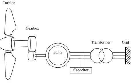
2.2. Fixed Speed System
The first generating system is the oldest one. It consists of an induction generator, which is composed of a squirrel cage rotor and a stator with three distributed windings directly coupled to the grid through a transformer as illustrated in figure 2.1. The wind turbine rotor is coupled to the generator through a multiple-stage gearbox. This is the conventional concept applied by many wind turbine manufacturers during the 1980s and 1990s [17].
The fixed-speed wind turbine system often has two fixed speeds. This is accomplished by using two induction generators, one for low wind speeds (with lower synchronous speed) and the other for high wind speeds. One can also use a generator with two windings having different pairs. This leads to increased aerodynamic capture [20].
Fig. 2.1 Fixed speed concept with SCIG generator
The slip of a squirrel cage induction generator varies with the amount of power generated. Rotor speed variations are, however, very small, these are approximately 1 per cent [17, 21]. A squirrel cage induction generator always consumes reactive power, which is partly or fully compensated by capacitors in order to achieve one power factor.
The fixed-speed wind turbine has the advantage of being simple, robust and cheap. Although it allows stall-regulated generator when is connected to the grid, that is, stable frequency of the network. A simple pitch control method is generally combined with squirrel cage induction generator [17, 22].
SCIG Gearbox
Turbine
Transformer Grid
18
There are several disadvantages of squirrel cage induction generator for the fixed speed wind turbine. The speed is not controllable and is variable only over a very narrow range, in which only speeds higher than synchronous speed are possible for generator operation. With high slip we get high dissipation of electrical energy in the rotor bars. Also, the fixed speed concept means that all fluctuation in the wind speed are transmitted as fluctuation in the mechanical torque followed by fluctuation in the electrical power on the grid. What results is large voltage fluctuations, which will result into significant line loses. This causes high mechanical and fatigue stresses on the system (turbine blades, gearbox and generator) and may result in swing oscillations between turbine and generator shaft. In addition, the turbine speed cannot be adjusted with the wind speed to optimise the aerodynamic efficiency. Although a pole-changeable squirrel cage induction generator has been used in some commercial wind turbines, it does not provide continuous speed variations. Moreover, a three-stage gearbox is necessary for this wind turbine concept, which makes the nacelle much heavier; this is also much more costly. And there is the reactive power consumption which is uncontrollable [17, 22].
2.3. Variable-Speed Systems
Due to the high wind turbines, the technology has switched from fixed speed to variable speed. To allow variable speed operation, the mechanical rotor speed and the electrical frequency of the grid must be decoupled. This means that the generator is partially or completely decoupled from the grid by a power electronics converter.
Currently the most common variable-speed wind turbine configurations are as follows [21, 23]:
Limited variable speed concept,
Variable speed concept with a partial-scale power converter,
19
2.3.1. Limited Speed Concept
The limited variable speed concept is known as the OptiSlip concept, which was applied by Vestas company since the mid 1990’s [24]. In this concept, a wind turbine is connected to the wound rotor induction generator with variable resistance by means of a power electronic converter and pitch control method, as shown in figure 2.2. The stator is directly connected to the grid, while the rotor is connected in series with a controlled resistor. Variable-speed operation can be achieved by dissipating the energy collected by the rotor in the external resistor.
Fig. 2.2 Limited variable speed concept with WRIG.
Conversely, with the increase in variable speed range, means a high power dissipated in resistor, lower generator efficiency, and a higher rating resistor. A typical limited variable speed range is less than 10%. Moreover, reactive power compensation and a soft-starter are required for this concept [17, 24].
2.3.2. Variable Speed Concept with Multiple-Stage Gearbox.
Since wind speed varies, the mechanical power on the generator shaft cannot be kept constant when the rotor speed is fixed. With fixed speed concept we get mechanical oscillations in the drive train that contribute to variations in mechanical power and the major part of the mechanical power fluctuations will be transmitted into fluctuations in the electric
WRIG
Gearbox Turbine
Transformer Grid
20
output power. Because of that, and since 1990, most wind turbines over 1.5 MW output power have been changed to variable speed control concept. The variable speed control is necessary to get more efficiency of the turbine.
A wind turbine with variable speed pitch control has a multi-stage gearbox, a generator, a power electronic converter and a blade pitch system. The frequency of the generator is varied, for the grid connection we use the converter.
Between the cut-in wind speed and rated wind speed, the wind turbine of this concept is operated at fixed pitch with a variable rotor speed to maintain an optimal tip speed ratio. When the rated power is reached, the pitch control is used to maintain the rated power [24].
The advantages of this concept can be summarized as follows [24]:
Improved output power quality, performed reactive power compensation and smooth grid connection.
Increased energy capture.
Reduced noise.
Reduced mechanical stress of the drive train.
2.3.2.1.
The Doubly Fed Induction Generator System
The doubly fed induction generator (DFIG) corresponds to a variable speed wind turbine with a wound rotor induction generator connected to the grid through the power electronic converter, as illustrated in figure 2.3. Since the rating of a power electronic converter could be reduced to 30% of rated power, it makes this generator more attractive and popular from an economic point of view. Typically, by controlling the rotor active power flow direction, a speed range of ± 30% around the synchronous speed can be obtained [24].
21
Fig. 2.3 Variable speed concept with DFIG.
Compared with the Optislip concept, the rotor energy is injected into the grid, instead of being dissipated into resistor. Also, the power converter system can perform reactive power compensation and smooth grid connection [17].
There are many manufacturers, such as Vestas, Gamesa, Repower, Nordex, using this DFIG in the market. The largest capacity for the commercial wind turbine product with DFIG has reached up to 5 MW from Repower [17].
However, the DFIG system has the following disadvantages [17, 24].
Heat dissipation by friction of gearbox
Regular maintenance of gearbox
Audible noise from gearbox
High torque peaks in the machine and large stator peak currents under grid fault conditions
The slip ring is used to transfer the rotor power, which requires a regular maintenance, and maybe results in machine failures and electrical losses.
Under grid fault conditions, on the one hand, the large stator currents result into large rotor currents. So, the power electronic converter needs to be protected
DFIG Gearbox
Turbine
Transformer Grid
22
from being destroyed. On the other hand, large stator peak currents may cause high torque loads on the drive train of wind turbines.
In case of grid disturbances, the control capability of DFIG is required which makes control strategies very complex. Detailed transient models and good knowledge of the DFIG parameters are needed to make a correct estimate of occurring torques and speeds.
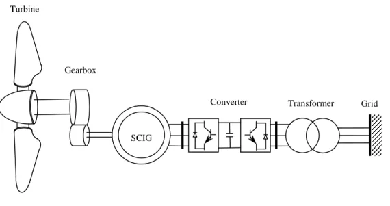
2.3.2.2.
Squirrel Cage Induction Generator System
A squirrel cage induction machine (SCIG), with a rotor connected to the grid via a power electronic converter, is also an alternative for variable speed. In this case, the capacitor bank is replaced by a full scale converter, which enables variable speed operation whatever the speed of the wind, as shown in figure 2.4.
Siemens is using this concept in the model of Bonus 107-3.6 MW on the market [24].
Fig. 2.4 Multiple-stage geared SCIG concept with full-scale converter.
2.3.2.3.
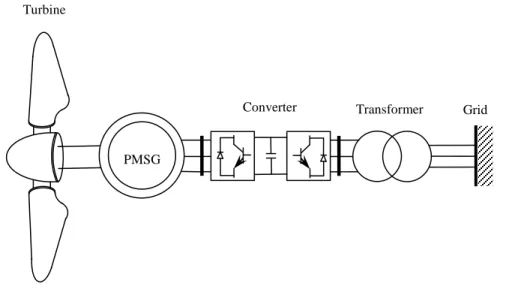
Permanent Magnetic Synchronous Generator System
A permanent magnetic synchronous generator (PMSG) connected to the grid through a full scale converter is a possible configuration for a variable speed system. The converter converts the variable-frequency generator voltage into the grid frequency.
SCIG Gearbox
Turbine
Transformer Grid Converter
23
In recent years, the use of PMSG is more attractive than before because the performance of permanent magnetic (PM) is improving and the cost of PM has been decreasing. Currently, Harakosan and Mitsubishi are using this concept in 2 MW wind turbines in the market [17].
The advantages of PMSG can be summarized as follows[17]:
Higher efficiency and energy yield,
No additional power supply for the magnet field excitation,
Absence of field losses,
Lesser losses due to the absence of mechanical components such as slip rings,
Lighter and therefore higher power to weight ratio. However, PMSG have the following disadvantages [17]:
High cost of PM material,
Difficulties to handle in manufacture,
Demagnetisation of PM at high temperature.
PM machines are not standard machines and they allow a great deal of flexibility in their geometry, therefore various topologies may be used. PM machines, based on the direction of flux penetration, can be classified into three types: radial flux, axial flux and transversal flux [16–28].
2.4. Variable Speed Direct-Drive Concept
Synchronous generators or permanent-magnet synchronous generators can be designed with multiple poles. This implies there is no need for a gearbox; see figure 2.5.The direct-drive generator rotates at low speed because the rotor of generator is directly connected on the hub of rotor blades. The direct-drive generator can be classified to two concepts: the electrically excited synchronous generator (EESG) and the permanent magnet synchronous one (PMSG).
24
Fig. 2.5 Direct-drive PMSG concept.
The advantages of the direct-drive generator compared to the geared generator can be summarized as follows:
Heavy and simple by omitting the gearbox
High efficiency and reliability
High availability
Low noise
However direct-drive generators have the following disadvantages:
Large weight and diameter of the generator
High cost
While considering the energy yield and reliability, direct-drive systems seem to be more powerful than the geared ones, especially for the offshore [24].
2.4.1.
Electrically Excited Synchronous Generator
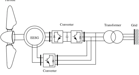
The electrically excited synchronous generator (EESG) is directly driven by the turbine with a rotor carrying a DC field excitation system, figure 2.6. The control of the synchronous generators feeding the grid is indispensable to maintain the frequency and voltage constant at
PMSG Turbine
Transformer Grid Converter
25
their rated values. The generator speed is fully controllable over a wide range, even to very low speeds [24, 25].
The main advantage of the EESG is that it can operate at any arbitrary power factor due to the independent control of the electrical excitation. Compared with geared generator it has normally a non-negligible manufacturing cost, generates some acoustic noise, requires regular maintenance (lubrication), and is also a potential cause of mechanical failure. The active and reactive power can be fully controlled in case of normal and disturbed grid conditions [24].
Fig. 2.6 Direct-drive EESG concept.
Some disadvantages of direct-drive EESG can be summarized as follows:
The cost of both generator and power electronic converter is considerably more expensive than a DFIG system. The converter has to process all the rated power which requires more expensive power electronic components and needs intensive cooling. Also, the generator needs a specific design and is very costly. Compared with normal electrical machines, it has to supply high electrical torques at low speeds. In addition, it is necessary to excite the rotor winding with DC, using slip rings and brushes, and in this case the field losses are inevitable [17, 24]. EESG Turbine Transformer Grid Converter Converter
26
2.4.2.
Permanent Magnetic Synchronous Generator
Direct-drive permanent magnetic generator system is more superior in terms of the energy yield, reliability, and maintenance problem [26]. That is why they are becoming more attractive; figure 2.5. The advantages of direct drive permanent magnetic synchronous machines can be summarized as follows [24, 26]:
Higher efficiency and energy yield.
No additional power supply for the magnet field excitation.
Improvement in efficiency due to absence of field losses.
Higher reliability due to absence of slip rings.
Higher torque density.
The disadvantages of the direct-drive permanent magnetic synchronous generator are [26]:
Relatively new technology for applications in larger MW-range
Difficult assembly of the generator
High costs of the permanent magnets
Low material reliability in harsh atmospheric conditions (offshore)
Demagnetization of PM at high temperature
Recently, the use of PM materials is more attractive, because the performance of PM materials is improving and the cost of PM materials is decreasing. The development makes PM machines with a full-scale power converter more attractive for direct-drive wind turbines. Currently, Zephyros (today's Harakosan) and Mitsubishi are using on the market this concept in 2 MW wind turbines [17].
2.5.
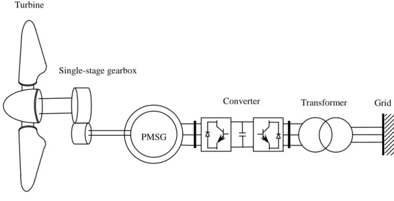
Variable Speed Concept With Single-Stage Gearbox
In this scheme, a wind turbine is connected to a single-stage gearbox that increases the speed by a factor of roughly 10 and to low-speed permanent-magnet generator. This concept is shown in figure 2.7. This model has attracted attention because it has the advantages of a higher speed than the direct-drive concept and lower mechanical component than the
multiple-27
stage gearbox one. Wind turbine manufacturers, such as Multibrid and Winwind, have products in the market based on this concept [17, 24].
Fig. 2.7 Single-stage drive PMSG with full-scale coverter.
2.6. Variable Speed Concept With Hydraulic Gearbox System
Wind turbines that swap traditional mechanical gearbox for hydraulics could be lighter, more reliable, and less costly.
Instead of putting inside the nacelle the turbine blades, a multi-ton planetary gearbox, a synchronous generator and a cabinet full of electronics converts, why not just put a hydraulic pump there and let the hydraulic pressure spin a generator on the ground; figure 2.8.
Such hydraulic systems would eliminate the need for mechanical gearboxes. Consequently, the overall wind-turbine mechanics would be less complex. And a setup of this nature would decouple torsional vibrations generated in the rotor hub from the generator. Also, a hydraulic pump would have less inertia and thus would let the turbine begin generating power in lighter winds. So, such systems would have lower operating costs.
But there is some disadvantage to this concept. The hydraulic solution would be from 10 to 30% less efficient than the electromechanical system. There are line losses encountered in moving the hydraulic fluid up and down the length of the tower for a split system. And it is not easy to scale up multimegawatt turbines [27].
PMSG Turbine
Transformer Grid Converter
28
Fig. 2.8 Simple hydraulic wind turbine.
2.7.
Performance Comparisons
Different generators concept of the wind turbines have been discussed by a number of authors [28-32].
According to [28, 17], the diameter of the direct drive PMSG is two times longer than that of geared-drive SCIG. But, the total length is two to three times shorter than that of SCIG. Also, the direct-drive PMSG system has its average efficiency of 2.3% and 1.6% higher than the fixed speed SCIG system at the 500 kW and 3 MW rated power, respectively. Furthermore, the direct-drive PMSG system can produce 5–10% more energy than the fixed two-speed concept, or 10–15% more than the fixed single-speed one. The detailed results are given in Table 2.1.
Table 2.1 Comparison of the direct-drive PMSG and the fixed-speed SCIG concepts [17]
Generators concepts PMSG SCIG PMSG SCIG Rated power, KW 500 500 3000 3000
Outer diameter of generator, m 2.7 1.5 5 2.5
Length of system 1.2 3 2 6
Average efficiency, % 90.7 88.4 91.6 90.0
On the other hand, comparison between the direct-drive PMSG and the geared-drive SCIG of 500 kW wind turbines was shown in Table 2.2. The annual energy production of the
Grid Transformer Generator Hydraulic motor Hydraulic line Hydraulic pump Turbine
29
direct-drive PMSG is higher than that of the geared-drive conventional SCIG. Although the wind turbine rotor diameter of the direct-drive PMSG is greater than that of the geared-drive SCIG, the total weight of the rotor and nacelle is lower [29, 17].
Table2. 2 Comparison of two 500 KW wind turbines with the direct-drive PMSG and fixed-speed SCIG system [17].
Generators concepts PMSG SCIG Speed of wind turbines rotor, rpm 18-38 30
Speed of generator rotor, rpm 18-38 1500
Annual energy production at mean wind speed, KWh
5 m/s 615 525
10 m/s 2350 2189
Wind turbine rotor diameter, m 40.3 38.2
Wind turbine weight, ton
Rotor, including hub 20.5 9.2
Nacelle 5.6 19.9
Rotor + nacelle 26.1 29.9
Tower 34.0 27.8
Total 60.1 56.9
In [31, 32, 17], a 1.5 MW direct-drive wind turbine system with EESG is compared with the DFIG system having a multi-stage gearbox. It is mentioned that the direct-drive system would be more expensive and heavier than the DFIG wind turbines. Also, the comparison between the direct-drive PMSG and EESG shows the cost for active material of PMSG is lower.
In [30, 17] are presented comparison of five 3 MW different generator systems for variable speed wind turbine concepts. The dimensions and performances of the comparison are presented in Table 2.3. The outer diameter of the direct-drive wind generator is usually larger than the geared-drive generator, but the total length is shorter. It is clear that the DFIG3G is the lightest, low cost solution, explaining why it is most widely-used commercially. However, it has a low energy yield due to the high losses in the gearbox. For direct-drive wind turbine topologies, PMSG DD has the highest energy yield, EESG DD appears to be the heaviest and most expensive concept. PMSG 1G has a better performance than PMSG DD with respect to the energy yield per cost.
30
Table 2.3 Comparisons of five wind generator concept [17].
Generators concepts DFIG 3G EESG DD PMSG DD PMSG 1G DFIG 1G Stator air-gap diameter, m 0.84 5 5 3.6 3.6
Stack length, m 0.75 1.2 1.2 0.4 0.6
Active material weight, ton
Iron 4.03 32.5 18.1 4.37 8.65
Copper 1.21 12.6 4.3 1.33 2.72
PM 1.7 0.41
Total cost, KEuro 5.25 45.1 24.1 6.11 11.37
Generator active material 30 287 162 43 67
Generator construction 30 160 150 50 60
Gearbox 220 120 120
Converter 40 120 120 120 40
Sum of generator system cost 320 567 432 333 287
Total cost KWh/Euro 1870 2117 1982 1883 1837
Annual energy yield, MW h 7690 7740 7890 7700 7760
Annual energy yield / total cost, KW h/Euro 4.11 3.67 3.98 4.09 4.22
2.8.
Market Status
Table 2.4 shows some wind turbines with a rated power over 2 MW from different manufactures, in which the concept, generator type, rated power and manufactures are summarized.
As it can be seen, most manufactures are using geared-drive wind turbine concepts. Also, it is clear that the wind market is still dominated by DFIG with a multiple-stage gearbox and the mostly used generator type is still the induction generator (DFIG, SCIG and WRIG).
31
Table 2.4 Wind turbine concepts on the market over 2 MW [17]
Wind turbine concept Generator Type
Power / Rotor diameter / Speed
Manufacturer
Variable speed multiple-stage concept with partial-scale power converter
DFIG 4.5 MW / 120 m / 14.9 rpm Vestas 2 MW / 90 m / 19 rpm Gamesa 3.6 MW / 104 m / 15.3 rpm GE Wind 5 MW / 126 m / 12 rpm Repower 2.5 MW / 90 m / 14.85 rpm Nordex 3 MW / 100 m / 14.25 rpm Ecotecnia
Limited variable speed with multiple-stage gearbox
WRIG 2 MW / 88 m / 17 rpm Suzlon
Variable speed multiple-stage gearbox with full-scale power converter
SCIG 3.6 MW / 107 m / 13 rpm Siemens Wind Power PMSG 2 MW / 88 m / 16.5 rpm GE Wind Variable speed single-stage gearbox
with full-scale power converter
PMSG 5 MW / 116 m / 14.8 rpm Multibrid
3 MW / 90 m / 16 rpm Winwind
2.5 MW / 93 m / 15.5 rpm Clipper Windpower
Variable speed direct-drive with full-scale power converter
EESG 4.5 MW / 114 m / 13 rpm Enercon
PMSG 2 MW / 71 m / 23 rpm Zephyros
Figure 2.9 presents an overview of the market share for each wind turbine concept over the years 1995-2005. As it can be seen, the fixed-speed SCIG concept has decreased about threefold over 11 years, from almost 70% in 1995 to less than 20% in 2005. Market penetration of WRIG has declined since 1997 in favour of the more attractive variable speed concept DFIG. It is clear that WRIG is being phased out of the market. The DFIG has increased from 0% up to more than 60% of the yearly installed wind power over 11 years, becoming the most dominant concept by the end of 2005. Market penetration of SG concept (EESG or PMSG) has altered little over the years. During the analyzed years, SG concept has ranked third or fourth [33].
32
Fig. 2.9 World share of yearly installed power for different wind generator systems [33].
2.9.
Technology Trends
With fast development of wind turbine technologies, future trends in the wind turbine industry will be focused on:
Super-large wind turbine designs: since 2003, attention has been focused on 1.5 MW wind turbine and there is higher demand for these products. Today, only two real concepts in the MW size exist within the industry and the difference is limited to using a gearbox with an asynchronous generator or a synchronous ring one [17, 34]. On the engineering side, they focused on scaling-up wind turbines so as to improve mechanical strength for rotor blades. Up to now, the research works for super-large wind turbine designs in particular for offshore wind turbine power generators are rated at 10 MW to 20 MW [17, 35].
Offshore site production: unlike offshore site production, few sites are available on land where the wind profile is appropriate for wind power generation. Out at sea there can be up to 40% more wind than on land. In addition, wind turbine sizes are increasing to more efficiently capture wind energy. With increasing sizes, the systems can be transported more easily via water than overland. For this reason, the offshore wind farms sites productions have been increasing, yet their technology has not yet been developed to its full potential. Everything
19950 1996 1997 1998 1999 2000 2001 2002 2003 2004 2005 10 20 30 40 50 60 70 80 Year S ha re of ye a rl y ins ta ll e d pow e r [ % ]
33
indicates that the future of offshore production projects will be more promoting [36, 39].
Direct drive wind turbine: to cut costs and improve reliability, the industry is trying to scale up the equipments of wind energy system. The wind turbine market of direct drive is growing fast since the last years; it has a better efficiency and reliability. Direct drive technology is captured approximately up to 17.4% share in global wind turbine market for the year 2010 and it is expected to capture up to 24.3% of overall wind turbine installation by 2016 [40, 41]. Furthermore, the use of permanent magnetic PM machines is becoming more attractive than ever before because the performance of PM materials is improving and the cost of PM materials is decreasing during the recent years. These advantages make direct drive PM wind generator systems more attractive for wind turbine concepts, especially for offshore applications [26]. It is expected that larger low-speed generators that don't require geared transmission will replace traditional gearboxes and high-speed generators.
2.10. Large Turbine Challenge
The goal of a larger turbine is to increase efficiency by capturing more wind energy using longer blades. Thanks to reliable and efficient offshore wind energy, several offshore wind projects have been adopted. The offshore applications require larger turbine units, the sizes wind turbine is about 7 MW at the present time and the largest turbines in the near future would be about 20MW. Danish company Vestas was offered its 7 MW offshore giant in 2011, GE Global Research announced the development of generator to support large-scale wind turbines in the 10-15 MW range. Also, UpWind, starting with a reference 5 MW wind turbine, has initially extrapolated this reference design to upscale it to 10 MW, and then up to 20 MW [43, 45].
This virtual 20 MW design was impossible to manufacture and it is uneconomic. It would weigh 880 tonnes on top of a tower making it impossible to carry and support such a mass. The blade wall thickness would also exceed 30 cm, which puts constraints; the blade length would also require new types of fibres in order to resist the loads [45].
34
2.11.
Conclusions
The development, configurations and characteristics of different wind generators concepts, with their advantages and disadvantages, have been reviewed. A detailed analysis has been presented with the quantitative comparison of different wind generator concepts as well as their market penetration. The developing trends of wind generator systems have been presented and some wind systems challenges exposed.
The multiple-stage geared drive DFIG concept is still dominant in the current market, due to the fact that it is the lightest and is a low cost solution. However, it has a low energy yield because of high losses in the gearbox.
Additionally, the market shows interest in the permanent magnet direct drive with a full-scale power electronic converter. The performance of permanent magnets PMs is improving and the cost of PMs is decreasing in the recent years. This makes variable speed direct-drive PM machines with full-scale power converter more attractive for offshore wind power generations. In one word, permanent magnet direct drive turbines are the future of wind energy generation.
Big MW-size turbines, due to the pressure of reducing the energy cost, have become the dominant machines in the commercial market. In the near future wind turbine rated power would attain 10 MW. Thus, the current developments of wind turbine concepts are more and more being directed to offshore wind energy.
35
CHAPTER 3
MAGNETIC POWER-SPLIT
CONTINUOUSLY VARIABLE
TRANSMISSION CVT
3.1. Introduction
Mechanical gearboxes are used extensively both for increasing and decreasing the rotational speed. However, they cause vibration, wear and noise by reason of direct contact. Also, the more we employ a high-speed electrical machine together with a gearbox to transform speed and torque, the more it is costly and heavier. Not to mention that lubrication is needed for practical use. A magnetic gear having no direct contact solves all these problems. In 2001, the high-torque magnetic gear was invented and demonstrated by Dr Kais Atallah, University of Sheffield, U.K [46]. A magnetic gear uses permanent magnets to transmit torque between an input and output shaft without mechanical contact. This means no wear and lubrication is required. Magnetic gears offer several advantages, such as lubricant-free operation, reduced maintenance costs, quiet operation between the input and output shafts, physical isolation between input and output shafts, and inherent overload protection [47, 52]. The topology and a high performance of magnetic has been presented in [50], simulation and experimental studies have shown that this gear has a transmitted torque density capability comparable with three-stage helical gearboxes, viz. 50-150 KNm/m3 [15]. They also can be used as magnetic torque-limiter; the gear will harmlessly slip when a torque reaches the reference torque [51].
This chapter describes the design and performance of a magnetic gear topology employing rare-earth magnets. Its principle of operation was introduced in [50]. Such a magnetic gearbox could offer significant advantages in applications like wind power generation.
36
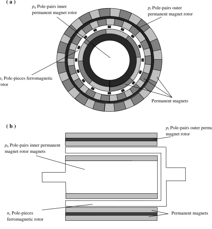
3.2. Topologies Of Magnetic Gearbox
The magnetic gear topology shown in figure 3.1, whose principle of operation was introduced in [50]. It consist of three components; an inner permanent magnet rotor with ph
pole-pairs, an outer permanent magnet rotor with pl pole-pair and ferromagnetic pole-pieces ns
between the two rotors.
( a )
( b )
Fig. 3.1 The magnetic gear.
(a) Radial cross section. (b) Axial cross section.
pl Pole-pairs outer permanent
magnet rotor
magnets
ph Pole-pairs inner permanent
magnet rotor magnets
ns Pole-pieces
ferromagnetic rotor
Permanent magnets
ph Pole-pairs inner
permanent magnet rotor magnets
ns Pole-pieces ferromagnetic
rotor
pl Pole-pairs outer
permanent magnet rotor
magnets
37
3.3. Principle Of Operation
The number of pole-pairs in the space harmonic flux density distribution produced by either the high or low speed rotor permanent magnets is given by [50]:
𝑝𝑚 ,𝑘 = 𝑚𝑝 + 𝑘𝑛𝑠
𝑚 = 1, 3, 5, 7, … , ∞ (3.1)
𝑘 = 0, ±1, ±2, ±3, . . ., ±∞
p is the number of pole-pairs on permanent magnet rotor, and ns the number of stationary
steel pole-pieces.
The rotational velocity of the flux density space harmonics is given by [4]:
𝜔𝑚 ,𝑘 = 𝑚𝑝
𝑚𝑝 +𝑘𝑛𝑠𝜔𝑟 +
𝑘𝑛𝑠
𝑚𝑝 +𝑘𝑛𝑠𝜔𝑠 (2.3)
ωr and ωs are the rotational velocity of the permanent magnet rotor and ferromagnetic
pieces respectively. To transmit torque at a different rotational speed, the number of pole-pairs of the other permanent magnet rotor must be equal to the number of pole-pole-pairs of a space harmonic for which k ≠ 0 [15].
The gear ratio is given by [50]:
𝐺𝑟 = 𝑚𝑝 +𝑘𝑛𝑠
𝑚𝑝 (3.3)
Since the combination m = 1, k = -1, results in the highest asynchronous space harmonic and the gear ratio is then given [15]:
𝐺𝑟 = 𝑛𝑠−𝑝
𝑝 (3.4)
To illustrate the variation of flux density distribution of magnetic gear, we take the simulation studies in [50]. Table 3.1 gives the parameters of the magnetic gear, shown in figure 3.1.
38
Table 3.1
Parameters of magnetic gear [50]
Parameter
Number of pole-pairs on high speed rotor ph = 4
Number of pole-pairs on low speed rotor pl = 22
Number of stationary steel pole-pieces ns = 26
Air gap length 1 mm
Outside diameter 140 mm
Remanence of sintered NdFeB Br = 125 T
Relative recoil permeability of sintered NdFeB µr = 1.05
3.3.1. Flux Density Waveforms
[15, 50, 54, 55] have shown the variation of the radial component of flux density. The modulation of the magnetic fields produced by each of the permanent magnet rotors by the ferromagnetic pole-pieces, such that appropriate space harmonics having the requisite number of poles as the associated permanent magnet rotor result. The flux density distribution at a radial distance r produced by either permanent magnet rotor is given in [15].
Fig. 3.2 Variation of radial flux density due to high speed rotor adjacent to low speed rotor [50]. - - - - - Without pole-pieces --- With pole-pieces Flux density ( T ) 0° 30° 60° 90° 120° 150° 180° 210° 240° 270° 300° 330° 360° 0 0.5 -0.5 - - - - - Without pole-pieces --- With pole-pieces
39
Figure 3.2 shows the variation of the radial component of flux density due to the high speed rotor permanent magnets in the airgap adjacent to the low speed rotor, while the ferromagnetic pole-pieces are stationary, i.e. ωs = 0. And figure 3.3 shows the corresponding
space harmonic spectrum. It can be seen that the presence of the steel pole-pieces results in a number of asynchronous, viz. k ≠ 1, space harmonics, the largest of which is the 22 pole-pair space harmonic, (m = 1, k = -1), which interacts with the 22 pole-pair low speed rotor permanent magnets to transmit a torque at a rotational velocity [50, 56]:
𝜔𝑙 = 𝑝ℎ
𝑝ℎ−𝑛𝑠𝜔ℎ = −
1
5.5𝜔ℎ (3.5)
ωh and ωl are the rotational velocities of the high and low speed rotors respectively.
In the same way, figure 3.4 shows the variation of the radial component of flux density due to the low speed rotor permanent magnets in the airgap adjacent to the high speed rotor, while the ferromagnetic pole-pieces are stationary, i.e. ωs = 0.
0 4 8 12 16 20 24 28 32 36 40 44 48 1.0 0.8 0.2 0.6 0.4 Pole-pairs Harmonic (P.U.)
Fig. 3.3 Space harmonic spectrum of radial flux density due to high speed rotor adjacent to low speed rotor [50].
40
And figure 3.5 shows the corresponding space harmonic spectrum. It can be seen that the presence of the steel pole-pieces results in a dominant 4 pole-pair asynchronous space harmonic, (m = 1, k = -1), which interacts with the 4 pole-pair high speed rotor permanent magnets to transmit torque at a rotational velocity [50, 56]:
𝜔ℎ = 𝑝𝑙 𝑝𝑙−𝑛𝑠𝜔𝑙 = −5.5𝜔𝑙 (3.6) 0° 30° 60° 90° 120° 150° 180° 210° 240° 270° 300° 330° 360° 0 0.1 -0.1 Flux density ( T ) - - - - - Without pole-pieces --- With pole-pieces
Fig. 3.4 Variation of radial flux density due to low speed rotor adjacent to high speed rotor [50].
41
3.3.2. Torque Transmission
Figure 3.6 and figure 3.7 illustrate the variation of the maximum torque which is exerted on the high and low speed rotors as they rotate. As can be seen, a transmitted torque density can be reach high value [50, 57, 58]. As well, it had demonstrated in [15] that the maximum torque varies with the radial thickness of the pole-pieces which mean that an optimum thickness for the pole-pieces exists that result in the maximum torque transmission capability. Also the choice of the combination of the number of pole-pairs on the input and output rotors and number of pole-pieces has a significant influence on the maximum torque transmission.
0 4 8 12 16 20 24 28 32 36 40 44 48 1.0 0.8 0.2 0.6 0.4 Pole-pairs Harmonic (P.U.)
Fig. 3.5 Space harmonic spectrum of radial flux density due to low speed rotor adjacent to high speed rotor [50].
42
3.3.3. Cogging Torque
It is important to consider the cogging torque since this may be detrimental to the performance of the magnetic gear. The cogging torque results from interaction between the ferromagnetic pole-pieces and both the input rotor and the output rotor, qualitatively, the cogging torque is determined by the cogging torque factor, 2p ns / Nc, where Nc is the smallest
0 5 10 15 20 0 50 100 150 200 250 300 350
Angular position of high speed rotor ( ° )
T or que of hi gh spe ed rot or ( N m / m ) 0 0.5 1 1.5 2 2.5 3 3.5 4 0 200 400 600 800 1000 1200 1400 1600
Angular position of low speed rotor ( ° )
T or que of l ow s pe ed rot or ( N m / m )
Fig. 3.7 Variation of maximum torque on low speed rotor [50]. Fig. 3.6 Variation of maximum torque on high speed rotor [50]
43
common multiple between the number of poles 2p (2ph or 2pl) and the of ferromagnetic
pole-pieces ns [54, 59]. For the magnetic gear, table 3.1, ph = 4, pl = 22, ns = 26, the cogging torque
factor is 2.
3.3.4. Equation Of Motions
The equation relating the motions of the different components of the gear is given by [50]:
𝑝ℎ𝜔ℎ+ 𝑝𝑙𝜔𝑙 = 𝑛𝑠𝜔𝑠 (3.7)
To have a fixed-ratio magnetic gear, one of the three components of the gear is held stationary, while the other components are connected, so we have three cases:
Stationary pole-piece array (𝝎s = 0)
According to the equation 3.7, the gear ratio is:
𝐺𝑟 = − 𝑝𝑙
𝑝ℎ (3.8)
Stationary outer magnet array (𝝎h = 0)
According to the equation 3.7, the gear ration is:
𝐺𝑟 = 𝑛𝑠
𝑝𝑙 (3.9)
Stationary inner magnet array (𝝎l = 0)
From the equation 3.7, the gear ration is:
𝐺𝑟 = 𝑛𝑠
𝑝ℎ (3.10)
According to the equation 3.7, if the input shaft is connected to the inner magnet array and the output shaft is connected to the pole-piece array, the speed of the output shaft can be written as follows:
𝜔𝑠 = 𝑝𝑙
𝑛𝑠𝜔𝑙 +
𝑝ℎ
𝑛𝑠𝜔ℎ (3.11)
And the output torque Ts is related to the input torque Tl as follows:
𝑇𝑠 = 𝑛𝑠
44
From equation 3.7, it can be seen that even if the input speed 𝝎l varies, the output speed
𝝎s can be kept constant by controlling 𝝎h.
3.4. Wind Energy Application
This work describes approach to creating a machine by combining a magnetic gear and permanent magnet synchronous machine both mechanically and magnetically [54].
Figure 3.8 shows a schematic of the proposed magnetically and mechanically coupled magnetic gear and synchronous machine. For a given input speed, which is governed by the turbine speed, the output speed is maintained at the synchronous speed by controlling the speed of the control rotor of the magnetic gear.
3.4.1. Electromechanical Modelling
For the magnetic gear machine shown in figure 3.8, the input shaft is connected to the inner magnet rotor, the output shaft is connected to the pole-piece rotor and the outer magnet rotor is used like controller rotor
Fig. 3.8 Magnetic gear under variable speed.
To see the behaviour of the magnetic gear, the input shaft is connected to the variable speed, the output shaft is connected to variable load and we used the controlling rotor to kept the output shaft to a reference speed ωs*.
Controlling rotor, ωh Variable input
speed, ωl
45
Since the torque is transmitted magnetically from the input rotor to the output rotor, the equations which govern the motion of the input rotor, output rotor and the ferromagnetic rotor are [51, 53, 54, 59]: 𝐽𝑙𝑑ω𝑙 𝑑𝑡 = 𝑇𝑚𝑒𝑐 1− 𝑇𝑚𝑎𝑥 𝑝𝑙 𝑛𝑠sin 𝑝𝑙𝜃𝑙 + 𝑝ℎ𝜃ℎ − 𝑛𝑠𝜃𝑠 (3.13) 𝐽ℎ𝑑ωℎ 𝑑𝑡 = 𝑇𝑚𝑒𝑐 2− 𝑇𝑚𝑎𝑥 𝑝ℎ 𝑛𝑠sin 𝑝ℎ𝜃ℎ + 𝑝𝑙𝜃𝑙 − 𝑛𝑠𝜃𝑠 (3.14) 𝐽𝑠𝑑ω𝑠 𝑑𝑡 = −𝑇𝑙𝑜 − 𝑇𝑚𝑎𝑥 sin 𝑛𝑠𝜃𝑠− 𝑝ℎ𝜃ℎ − 𝑝𝑙𝜃𝑙 (3.15)
Where θl, θs and θh are the angular position of the input rotor, the output rotor and the
control rotor respectively, Tmax is the maximum torque which can be produced by the magnetic
gear, Jl, Js and Jh are the inertia of the input rotor, the output rotor and the control rotor
respectively, Tmec1, Tmec2 are the mechanical torques and Tlo is the load torque.
3.5. Simulation Studies
A control scheme of the magnetic gear is represented in figure 3.9.
Fig. 3.9 A control scheme of magnetic gear
Torques Variable Load -C-Tmax Speeds ωh = 4.38 Reference Output Rotor Speed PI PI Controller Th = Tmec2 Tmax ωl Tload ωh ωl ωs Tl = Tmec1 Magnetic Gear
46
To check the behaviour of the magnetic gear, a dynamic simulation is implemented using variable speed in the input shaft figure 3.10 and variable load in the output shaft figure 3.11.
Fig. 3.10 Variable speed of the input rotor.
Fig. 3.11 Variable load of the output rotor.
0 0.2 0.4 0.6 0.8 1 1.2 1.4 1.6 1.8 2 0 5 10 15 20 25 30 35 Time ( s ) Input S pe e d S ha ft ( r a d/ s ) 0 0.2 0.4 0.6 0.8 1 1.2 1.4 1.6 1.8 2 0 5 10 15 20 25 Time ( s ) V a ri a bl e L oa d ( N .m )
47
Table 3.2 gives the parameters of magnetic gear which have a topology shown in figure 3.8.
Table 3.2 Parameters of magnetic gear
Number of pole-pairs inner rotor, pl 4
Number of pole-pairs outer rotor, ph 21
Number of pole-pieces, ns 23
Moment of inertia of inner rotor, Jl 0.0001 Kg.m2
Moment of inertia of outer rotor, Jh 0.0001 Kg.m2
Moment of inertia of pole-pieces rotor, Js 0.0001 Kg.m 2
From figure 3.12 and figure 3.13, it can be seen that even though the input speed ωl
varies, the output speed ωs can be kept constant by controlling ωh (ωs = 4.38 rad/s). Now, it is
confirmed that the three rotors of the magnetic gear are linked by the equation 3.11.
Fig. 3.12 The output speed ωs
0 0.2 0.4 0.6 0.8 1 1.2 1.4 1.6 1.8 2 0 1 2 3 4 5 6 7 8 9 Time ( s ) O ut put S pe e d S ha ft ( r a d/ s )
48
Fig. 3.13: The Controlling rotor speed ωh.
According to the figure 3.12, figure 3.14 and figure 3.15, the torque which needs to be applied to the controlling rotor is independent of the speeds of the rotors, and is a function of the applied input torque and gear ratio of the magnetic gear.
Fig. 3.14: The torque of the controlling rotor Th.
0 0.2 0.4 0.6 0.8 1 1.2 1.4 1.6 1.8 2 -1.5 -1 -0.5 0 0.5 1 Time ( s ) C ont rol li ng R ot or S pe e d ( ra d/ s ) 0 0.2 0.4 0.6 0.8 1 1.2 1.4 1.6 1.8 2 -5 0 5 10 15 20 Time ( s ) T or que of t he C ont rol li ng R ot or ( N .m )
![Table 2.1 Comparison of the direct-drive PMSG and the fixed-speed SCIG concepts [17]](https://thumb-eu.123doks.com/thumbv2/123doknet/2945947.79691/29.918.260.680.841.979/table-comparison-direct-drive-pmsg-fixed-speed-concepts.webp)
![Table 2.3 Comparisons of five wind generator concept [17].](https://thumb-eu.123doks.com/thumbv2/123doknet/2945947.79691/31.918.135.808.123.560/table-comparisons-wind-generator-concept.webp)
![Table 2.4 Wind turbine concepts on the market over 2 MW [17]](https://thumb-eu.123doks.com/thumbv2/123doknet/2945947.79691/32.918.136.815.125.687/table-wind-turbine-concepts-market-mw.webp)
![Fig. 2.9 World share of yearly installed power for different wind generator systems [33]](https://thumb-eu.123doks.com/thumbv2/123doknet/2945947.79691/33.918.293.672.114.398/world-share-yearly-installed-power-different-generator-systems.webp)