an author's
https://oatao.univ-toulouse.fr/22835
https://doi.org/10.1016/j.paerosci.2019.01.002
Huang, Xiao and Tepylo, Nick and Pommier-Budinger, Valérie and Budinger, Marc and Bonaccurso, Elmar and
Villedieu, Philippe and Bennani, Lokman A survey of icephobic coatings and their potential use in a hybrid coating/
active ice protection system for aerospace applications. (2019) Progress in Aerospace Sciences, 105. 74-97. ISSN
0376-0421
A survey of icephobic coatings and their potential use in a hybrid coating/
active ice protection system for aerospace applications
Xiao Huang
a, Nick Tepylo
a,∗, Valérie Pommier-Budinger
b, Marc Budinger
c, Elmar Bonaccurso
d,
Philippe Villedieu
e, Lokman Bennani
eaDepartment of Mechanical and Aerospace Engineering, Carleton University, 1125 Colonel By Drive, K1S 5B6, Ottawa, ON, Canada
bISAE-SUPAERO, Université de Toulouse, 31400 Toulouse, France
cInstitut Clément Ader, Université de Toulouse, INSA, ISAE-SUPAERO, MINES, ALBI, UPS, CNRS, 31400 Toulouse, France
dAIRBUS Central R&T, XRXG, 81663, Munich, Germany
eDepartment of Multiphysics for Energetic, ONERA, 2 Avenue Edouard Belin, 31500 Toulouse, France
Keywords: Icephobic coating De-icing Anti-icing Ice adhesion
Hybrid ice protection system Electro-mechanical de-icing
A B S T R A C T
Icephobic coatings for aircraft and other surfaces subjected to ice accretion have generated great interest in the past two decades, due to the advancement of nanomaterials, coating fabrication methods, biomimetics, and a more in-depth understanding of ice nucleation and ice adhesion. Icephobic coatings have demonstrated the ability to repel water droplets, delay ice nucleation and significantly reduce ice adhesion. Despite these ongoing research activities and promising results, thefindings reported hereafter suggest that coatings alone cannot be used for aircraft anti-icing and de-icing operations; rather, they should be considered as a complementary option to either thermal or mechanical ice protection methods, for reducing power consumption and the ecological footprint of these active systems and for expediting ground de-icing operations. This paper willfirst review the state-of-the-art of icephobic coatings for various applications, including their performance and existing de fi-ciencies. The second part of this paper focuses on aerospace anti-icing and de-icing requirements and the need for hybrid systems to provide a complete ice protection solution. Lastly, several urgent issues facing further development in thefield are discussed.
1. Introduction
Ice accretion on aircraft has an adverse impact on both safety and performance [1]. As such, there have been great efforts devoted to the development of strategies for de icing and anti icing.“De icing” refers to the removal of ice from aircraft surfaces and its methods include heating, vibration (contact or non contact), mechanical means (e.g., inflated boots on aircraft leading edges) and sprayed icing fluids [2] to remove any ice accretion, while “anti icing” is a preventive measure that delays or reduces ice accretion on surfaces so that the subsequent de icing process is not needed or less time/energy will be needed during de icing. Anti icing can be achieved by frequent spraying of anti freezing fluids or by the application of permanent coatings (hydro phobic or icephobic), designed to prevent water droplets from adhering to the surface before freezing, to delay the freezing event, and/or to reduce ice adhesion to the surface [3]. The use of de icingfluids for de
icing and anti icing purposes has a severe environmental impact [4,5], while a permanent, long lasting coating can lessen such consequence.
The development of icephobic surfaces can be dated back to the late 1950s [6,7]. However, due to the complexity of icing conditions and ice interaction with surfaces, there has not been a proven, commercially viable (low cost, easy application) and durable (repeated icing/de icing cycles, surface abrasion and mechanical loading) icephobic coating for aerospace applications thus far. Some promising coatings have shown to be able to reduce ice adhesion up to several orders of magnitude with respect to reference metal surfaces such as aluminium, titanium or steel, while others could delay ice crystal nucleation from supercooled water droplets or humid air for up to several hours. The purpose of this paper is tofirst briefly provide an overview of the aircraft ice accretion process and then summarize the latest icephobic coatings and their performance. The second part of the paper focuses on the requirements for effective aircraft anti icing and de icing strategies. Based on the
∗Corresponding author.
E-mail addresses: [email protected](X. Huang), [email protected](N. Tepylo), [email protected](V. Pommier-Budinger),
[email protected](M. Budinger), [email protected](E. Bonaccurso), [email protected](P. Villedieu),
[email protected](L. Bennani).
state of the art technologies, future development in combining active systems and engineered coating materials into a hybrid system are proposed.
2. Aircraft de-icing and anti-icing methods 2.1. Ice formation and accretion on aircraft
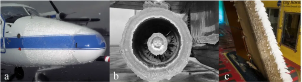
Ice accretion on aircraft duringflight can either be caused by im pinging supercooled water droplets, freezing rain, or snow particulates accumulating on the surface. The most common of these are super cooled water droplets which typically have a mean effective droplet diameter (MVD) less than 50 microns. The droplets impact the surface and can freeze on contact near the stagnation point or can roll back along the wing and freeze. Water can also exist in supercooled large droplets (SLDs) (typically larger than 50μm) that freeze upon contact and the release of their latent heat melts them back into the liquid phase where they refreeze further back on the aircraft [8,9]. In addition to droplet size, atmospheric conditions, airfoil geometry, aircraft velo city and angle of attack all together contribute to the formation and coverage of ice [10]. Ice accretion commonly occurs on the upper and lower wing surfaces, fuselage, propellers, engine nacelles, radomes and
sensor ports as shown inFig. 1. In addition to the general performance reduction, the adverse effects of icing on aircraft include wing stall, icing contaminated tail stall (ICTS), icing contaminated roll upset, en gine and air intake icing, carburetor icing, propeller icing, static and dynamic port blockage, probe icing and windshield icing.
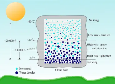
There are three types of ice that can form inflight; rime, glaze, and mixed ice. Rime ice consists of mostly frozen supercooled water dro plets and forms at low temperatures in stratiform clouds while glaze ice (partially frozen supercooled water droplets) forms just below the freezing temperature of water in mostly cumulus type clouds as out lined inFig. 2. Mixed ice forms in the middle of the freezing range which usually is between 0 and−20 °C (−40 °C in extreme conditions) [11]. Glaze ice can be difficult to remove as the supercooled water droplets exist mostly in the liquid state and are thus mobile once they contact the surface. The water droplets are able to coalesce, forming a sheet with a continuous bond to the surface. Since rime ice is generated from smaller droplets, they are unable to coalesce and as a result, freeze in place.
It was qualitatively determined that hydrophobic coatings can be more effective in glaze ice conditions than icephobic coatings under rime conditions [12]. The concentration and distribution of the super cooled water droplets and ice crystals inside the cloud vary with List of abbreviations
AIAA American Institute of Aeronautics and Astronautics
Al aluminium
AMIL Anti icing Materials International Laboratory
ARF adhesion reduction factor
ASME American Society of Mechanical Engineers
ASTM American Society for Testing and Materials
CA contact angle
CAH contact angle hysteresis
CFRP carbonfibre reinforced polymer
CNT carbon nanotube
CVD chemical vapour deposition
DLC diamond like carbon
DoE design of experiments
DRIE deep reactive ion etching
EIDI electro impulsive de icing systems
EMED electro mechanical expulsive de icing systems
ETIPS electro thermal ice protection systems
FAR Federal Aviation Regulations
FETS perfluorodecyltrichlorosilane
FOTS fluorooctyltrichlorosilane
FPD freezing point depressant
FPU fluorinated polyurethane
GFRP glassfibre reinforced polymer
GNRs graphene nanoribbons
HDFS heptadecafluoro 1,1,2,2 tetrahydrodecyl trichlorosilane
ICTS icing contaminated tail stall
IPS ice protection system
IWTT icing wind tunnel tests
LWC liquid water content
MVD mean effective droplet diameter
OEM original equipment manufacturer
PAA phosphoric acid anodizing
PDMS polydimethylsiloxane
PECVD plasma enhanced chemical vapour deposition
PFPE polyfluorinated polyether
PTFE polytetrafluoroethylene
PU polyurethane
PVD physical vapour deposition
PVDF polyvinylidenefluoride
REACH Registration, Evaluation, Authorisation and Restriction of Chemicals
RoA roll off angle
RTV room temperature vulcanizing
SA stearic acid
SAA sulphuric acid anodizing
SAE Society of Automotive Engineers
SAM surface assembled monolayer
SEM scanning electron microscopy
SLDs supercooled large droplets
SLIPS Slippery Liquid Infused Porous Surfaces
SMA shape memory alloy
TAT total air temperature
Ti titanium
TiAlN titanium aluminium nitride
TiN titanium nitride
UV ultraviolet
temperature and altitude as shown inFig. 3. As the temperature de creases, so does the saturated vapor density (the amount of water va pour the air can hold) while the probability of the droplets freezing increases, leading to a reduced icing probability. The ice accumulation rate is also related to the amount of supercooled water inside the cloud, where the highest amount of ice accretion would occur at temperatures just below the freezing point. Severe icing can also occur below the cloud level in freezing rain conditions.
Hoar frost, another form of ice, forms on the aircraft on the ground or inflight when descending from below freezing condition to an alti tude with warm and moist air. Frost accumulation on the surface can impact aircraft performance and visibility. It is more prone to form in areas with more surface asperities. i.e., rough surfaces. Snow, on the other hand, is a mixture of ice and water and its accumulation com monly occurs on the ground.
Frost, ice, and snow can also accumulate on aircraft surfaces while on the ground. If not removed, this accretion can reduce the lift by up to 30% and increase drag by 40% [13]. Allfive types of ice/snow accu mulation on aircraft are classified as “dangerous” to air traffic [1].
2.2. De icing and anti icing methods
Various ice protection systems (IPS) can be employed to protect aircraft surfaces, engine inlets, sensors and windshields from ice accu mulation inflight and on the ground. A summary of both existing and potential methods and their applications are provided inTable 1and
Table 2.
2.3. FAA certificated vs. non hazard
For flight certification, the FAA calls for a 45 min hold pattern duringflight in continuous, maximum icing conditions found in stratus clouds without the use of an ice protection system [14]. Unprotected surfaces to be tested include: landing gear, antennas, fuselage nose cones or radomes, fuel tank vents, fuel tip tanks, and the leading edge of control surfaces. A non hazard de icing or anti icing system should only be considered as a way for immediate escape from icing conditions. The non hazard de icing systems installed are not to be tested for perfor mance in icing conditions, rather they must show that in dry air, the installation of various systems does not adversely affect performance, stability, and otherflight characteristics. Due to this loose certification standard, these systems are considered non essential to the aircraft. For many of the coating systems discussed throughout this review, if they are to be used as FAA certified passive anti icing and de icing measures, rigorous tests must be conducted under the conditions stipulated in FAA certification once other standard tests have been carried out per cus tomer specifications.
3. Icephobic coating development
3.1. Hydrophobic/superhydrophobic vs. icephobic
Icephobicity and hydrophobicity have been considered closely
related and many icephobic coatings were in fact derived from hydro phobic or superhydrophobic coatings and surface processing methods. Although a standard definition of icephobicity has not yet been agreed upon, an extensive body of work exists in thefield of hydrophobic and superhydrophobic coatings. A brief overview of these surfaces is pro vided here. A more detailed, all encompassing review of this subject can be found in Ref. [15].
A surface is classified as hydrophobic when the water contact angle (CA) on this surface is > 90°; while a superhydrophobic surface has a
water contact angle > 150° and a contact angle hysteresis
(CAH) < 10° [16]. CAH is defined as the difference between the ad
vancing and the receding CA of a water droplet that expands or shrinks on surface. Alternatively, the roll off angle (RoA) can be determined as the lowest angle a surface needs to be inclined before a water droplet rolls or slides off it. Superhydrophobic surfaces should also exhibit RoA < 10° [17]. These definitions are illustrated inFig. 4.
Superhydrophobic coatings, most of which mimic the surface mi crostructure of water repellent plants or leaves, have been viewed historically as potential icephobic coatings in that they offer the ad vantage of reducing ice adhesion or accretion from supercooled water sprayed or poured onto the surface [18 20] (seeFig. 5). This was based on the reasoning that water and ice have a similar surface tension/ surface energy and that a surface that repels water should have the ability to prevent ice accretion as well.
Although superhydrophobic coatings have been investigated as part of an aircraft ice protection system [21], there are no studies conducted at aircraft cruise velocities (> 75 m/s) as noted by Yeong et al. [22] who recently performed tests in an icing wind tunnel at speed 50 and 70 m/s. Most of these studies use droplet impact velocities below 10 m/ s [23,24] or freezing conditions not in line with typical aircraft icing conditions [25,26]. In early work conducted on bare aircraft substrates, Scavuzzo and Chu demonstrated that the ice adhesion strength in creases with impact velocity [27]. In a similar study conducted on su perhydrophobic coatings, it was shown that the effectiveness of the coating decreased by increasing either the MVD or LWC [28]. Larger droplets have more momentum and thus are able to penetrate deeper into the surface asperities, increasing the effective contact area and the ice adhesion strength. Increases in the LWC promote frost formation which increases ice adhesion. Yeong et al. [22] obtained results at re latively high speed by generating rime and glaze ice on samples at 50 and 70 m/s with 20 micron MVD droplets. They showed that increasing droplet impact speeds tend to decrease the effectiveness of super hydrophobic coatings. They also found that the 20 micron MVD dro plets penetrate into the surface asperities and that the maximum Fig. 2. Ice characteristics for stratiform and cumuliform clouds.
Fig. 3. Ice formation within a cloud and the resulting probability of aircraft icing.
Table 1 In-fl ight de-icing and anti-icing methods on aircraft (summarized from Refs. [ 13 , 14 , 117 , 130 , 131 ]). Method Description of Technology De-icing Potential Anti-icing Potential Advantages and Disadvantages Freezing point depressants (FPD) (e.g., glycol) -Ice removed by pumping FPD through porous outer skin in-fl ight and spraying heated FPD on the ground -If a thin layer of FPD is remains on the aircraft surface, short-term anti-icing can be achieved Yes Yes -Can be used on the ground and in-fl ight -Layer of FPD on the aircraft can result in detrimental eff ects to aircraft performance -Fluids can be toxic and cause environment concerns Engine bleed air -Hot engine air redirected to the leading edge, heating the surface and melting the accreted ice -If no ice is present, it can prevent droplets from freezing and evaporate droplets on the surface Yes Yes -Reduction in engine effi ciency -Not available on piston and turboprop-powered airplanes -High system weight due to required internal piping Electro-thermal (embedded heaters) -Heating coils placed in the leading edge can melt accumulated ice when supplied with electrical energy -Can prevent the impinging droplets from freezing Yes Yes -Large power consumption, about 1.5 –2 W/cm 2 -Limited to critical areas -Surfaces must be thermally conductive Pneumatic boots -Rubber boots installed on the leading edge in fl ate with air to break accumulated ice into chunks Yes No -Rubber boots become rigid at low temperatures limiting eff ectiveness to temperatures > -20 °C -Require frequent dressing and inspection -Aerodynamic performance degradation when deployed Pneumatic impulse -Rubber boots are embedded in a metal or polymer system on the outside of the leading edge -When in fl ated, the boots expand rapidly, expelling any ice build-up Yes No -Protective layers consisting of metal or polymers are required to prevent the tubes from being exposed to rain erosion, ice pellet impingement and other forms of surface damage -Can remove ice at temperatures as low as − 55 °C Electro-impulse -High-voltage capacitors on the inside of the leading edge are rapidly discharged which generates an electromagnetic repulsive force in the skin causing fracture of ice bonded to the surface Yes No -Used to de-ice power transmission lines -May cause electromagnetic interference with other aircraft systems components -Can cause structural fatigue -No longer in use for aerospace Electro-expulsive separation system -Magnetic fi elds are generated about the two parallel layers of conductors, producing forces that push the conductors apart. When current is passed into the system, the rapid acceleration of the conductors breaks the bond the ice has formed with the surface Yes No -Short response time (ms) -Low power consumption (Tested on Cessna Skymaster and installed on Raytheon business jet) Shape memory alloys (SMA) -SMAs (e.g., NiTi) can change shape when heat is applied. If ice is present, the heat will cause the leading edge erosion shield to deform to a prede fi ned shape, expelling the ice Yes No -Only for leading edge erosion shields -Energy required is dependent on the surface temperature -Drag increase may be signi fi cant when deformed and during the return to its original shape Ultrasound technology [ 132 ] -When supplied with current, piezoelectric actuators on the inside of the leading edge produce ultrasonic waves that travel through the aircraft skin, generating shear stresses at interface between the ice and surface. These shear stresses debond and break apart the ice layer Yes Yes -Piezoelectric actuators require a lower power density than other methods for ice delamination -Actuator count required based on the size of surface needing protection -Bond strength to the surface may be fatigued after billions of cycles Microwave [ 131 ] -Microwave energy transferred through aircraft leading edge and converted to heat which melts the bond that ice has formed with the surface Yes Yes -Intended for use on turboprop aircraft -Can cause interference with other electronics -More energy intensive than other systems
roughness height to prevent this was approximately 10 nm. All these results appear to be significant obstacles for the field of super hydrophobic coating development.
In addition, the water repellent ability of micro textured super hydrophobic surfaces may be compromised, or even reversed (to hy drophilic) under frost forming conditions. In fact, frost can also form on micro textured superhydrophobic surfaces, which are water repellent only to liquid water drops and not to condensed water microdroplets. Once a frost layer is formed on the surface, the surface turns into a hydrophilic surface. Frost formation commonly occurs on the surface of many outdoor structures such as wind turbine blades, power lines, communication towers and aircraft on the ground. Duringflight, ice
accretion is usually due to supercooled water droplets impinging on aircraft surfaces.
The icephobicity of a surface not only depends on intrinsic surface properties, but also on the ice formation conditions. In a reported study of a surface with an array of hydrophobic silicon posts (Fig. 6), which was demonstrated to be a superhydrophobic surface for sessile water drops, the cooled surface frosted more readily under high humidity [18]. As a result, superhydrophobicity was lost, (the surface turned hydrophilic) due to the frost layer, and the increased effective surface area led to a higher ice adhesion strength when compared with smooth surfaces. In addition to experimental studies, theoretical force balance analysis also revealed that superhydrophobic surfaces were not ne cessarily icephobic [29]. As such, under different icing conditions, su perhydrophobicity does not always directly translate into icephobicity [30,31], particularly if the surface structure is not specifically tailored
to prevent frost formation. On the other hand, ice adhesion on non micro textured surfaces decreases as hydrophobicity increases [32,33].
3.2. General coating classification and requirements
Icephobic coatings can be classified based on their chemical com positions, surface topology and application methods. Polymer or com posite coatings in the forms of“paints”, that can be applied employing standard a spray, dip, brush, or an electrostatic deposition process, are beneficial for large structures such as aircraft and wind turbine blades. In contrast, coatings applied by either physical or chemical vapour deposition (PVD/CVD) or ion milling are rather applicable to smaller and higher cost devices, as these processes are carried out in an en closed chamber and the equipment and process costs are higher. Coatings fabricated using these processes also have limited thickness, which makes them less resistant to extreme weather conditions (freezing rain, dust particles, or ice crystals). Currently, the most pro mising icephobic coatings are based on two coating design principles:
surface micro and nano texturing followed by a chemical
Table 2
Anti-icing and de-icing methods used on different parts of aircraft [13].
Component Turbo-jet Propeller-driven aircraft Issues with potential use of coatings in combination with the already existing method of
de-icing
Airfoil leading edges - Engine bleed air
- Pneumatic boots
- Porousfluid panel
- Pneumatic boots
- Porousfluid panel
- Polymer coating will need to be heat conductive
- Anti-icing coatings on boots may be a viable choice, ifflexible
- Application of coatings on perforated surface may be challenging
Engine air intakes - Engine bleed air
- Pneumatic boots - Electrical heater mats
- Engine bleed air - Pneumatic boots - Electrical heater mats
- Similar to above - Similar to above
- Heating mats may be incorporated into the coating to reduce power consumption for de-icing
Propellers - Electric heater mats
- Fluid systems
-Similar to above -Advantageous if combined with a liquid infused coating system
Windshields - Electrical heaters - Electrical heaters - Similar to above
Pitot-static systems - Electrical heaters - Electrical heaters - Similar to above
Probes and drain masts - Electrical heaters - Electrical heaters - Similar to above
Control surface horns - Electrical heater mats - Electrical heater mats - Similar to above
Fig. 4. The contact angle and roll-off angle of a water droplet.
Fig. 5. Contact angle as a function of roughness factor (r = actual surface area/ geometric surface area) for different smooth surfaces of different CA. Reproduced from Ref. [127] with permission from Springer Nature.
functionalization (similar to superhydrophobic coatings based on the lotus leaf design) and infusing low surface energy polymeric matrices with functional lubricants (similar to slippery surfaces based on the Nepenthes pitcher plant design) [34].
For modelling ice adhesion to a smooth substrate, one can consider that the bonding strength on the atomic/molecular level depends upon three basic forces: electrostatic forces, covalent/chemical bonds, and van der Waals interactions [3]. The dielectric constant of a material affects the electrostatic attractive force; also, ice adhesion has been found to decrease with the dielectric constant of the surface material [35]. Teflon based materials have an inherently low dielectric constant (≈2) and are commonly used for hydrophobic and icephobic coating formulations. In fact, a RF sputtered Teflon showed almost negligible ice adhesion value when tested using a centrifugal ice adhesion appa ratus [36]. This shows that a low electrostatic force plays a significant role since van der Waals forces decay much more rapidly with distance than electrostatic forces. On the other hand, water (or ice), being a polar molecule with an exposed hydrogen atom, forms a strong bond with a substrate due to hydrogen bonding. The key to coating designs for reduced ice adhesion is to select materials with a low bonding strength to H2O. The effects of hydrogen bonds on the interface bonding
have been studied by many researchers [32,37,38]. Using a range of mixtures of zero hydrogen bonding with a hydrophobic surface as sembled monolayer (SAM) of 1 dodecanethiol and a surface with a hydrophilic nature like a SAM of 11 hydroxylundecane 1 thiol, ex perimentally determined ice adhesion values showed that hydrogen bonding was the greatest contributing factor to ice adhesion [38]. On a microscopic level, the ice adhesion strength to a substrate is also af fected by surface roughness, i.e., mechanical interlocking between the ice and substrate. The greater the surface roughness, the larger the mechanical adhesion is between the ice and substrate.
In summary, icephobic coatings can be designed by means of matrix compositions and topologies to achieve one or several of the following functions; these can also be used to define and compare icephobicity.
Detachment or removal of water droplets from a coated surface (ice droplets roll off surface before freezing).
Prevention or delay of ice formation via decreased heat transfer between impinging supercooled droplets and substrate so that ice crystallization is delayed.
Reduce the ice adhesion strength to the surface below 100 kPa so that minimum energy/force is needed for de icing (in a passive system, it was suggested that for a coating requires an ice adhesion strength below 20 kPa [39]).
In terms of ice adhesion strength, there exists a large variation in the published work for an individual substrate. This is in part due to the wide spectra of icing test conditions, ice thickness, the use of different adhesion test methods (lap shear, centrifuge, 0° cone test, bend test, knife edge test, impact [15,37]) and experimental variables. A review of the various testing methods and the measurements resulting from each test can be found in Ref. [40]. For example, the reported ice adhesion to
an uncoated aluminium (Al) substrate ranges from 110 [29] to
1360 kPa [41]. As such, in many instances ice adhesion will be de scribed qualitatively by the adhesion reduction factor (ARF) or com paratively throughout this communication. The ARF is a comparison between the adhesion strength of the icephobic coating and a reference surface (typically aluminium). A high ARF (> 10) is characteristic of an icephobic coating. Throughout the following sections on coatings, the durability in the form of resistance to mechanical and chemical attack will be commented, whenever such information is available.
3.3. Icephobic coatings and properties
There are several categories of icephobic coatings (illustrated in
Fig. 7) that will be outlined throughout this section. Ice adhesion strengths are reported; however, they may not be directly comparable due to the different physical test setups and selected parameters. 3.3.1. Polymer coatings based onfluoropolymers
Polytetrafluoroethylene (PTFE, commercially known as Teflon) bulk material, PTFE films, and fluorinated silicone rubber/polyurethane coatings were investigated to understand the effects of chemical com position and surface roughness on ice adhesion [42]. In one study, PTFE coatings were applied to aluminium substrates by a spray and sintering method (the sintering temperature of 350 370 °C is high for a fully heat treated aged hardened aluminium alloy). Thefluorinated coatings were applied by spraying and curing. The highest water contact angle, 152.8°, was recorded on one of the sintered PTFE surfaces. The sub micron grain structures, with gaps smaller than the mean water droplet Fig. 6. Scanning electron microscopy (SEM) images illustrating gradual frost formation on a superhydrophobic surface within 36 s at 13 °C. Figures reproduced from Ref. [18] with permission from AIP.
sizes, effectively trapped air and enabled a Cassie Baxter state of water on the PTFE surface as shown inFig. 8. The two images illustrate the different surface morphologies that resulted from the use of different raw powder material. The ice adhesion test, however, showed that both sintered PTFE coatings had very large ice adhesion strength under shear (1560 and 1820 kPa for the rod and spherical particles,Fig. 8a and b). In contrast, the smooth bulk PTFE has the lowest ice bonding strength (60 kPa). In another study, polyfluorinated polyether (PFPE) dip coating was able to reduce ice adhesion of a bare aluminium surface by a factor of 20, while Teflon provided a reduction of seven times [25].
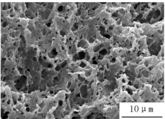
Polyvinylidene fluoride (PVDF) coating was applied on to wind
turbine blades made of glassfibre composite material to enhance ice phobicity. To create the roughened structure shown inFig. 9, NH4HCO3
was added to the PVDF solution [43]. The pore sizes ranged from 1 to 5μm, and a water contact angle of 156° and a water sliding angle of 2° were reported. Although an ice adhesion test was not conducted, an ice accretion test carried out at−10 °C with a water sprinkler (1 mm dia. water droplet size) spraying supercooled water onto horizontally placed samples, showed that there was negligible ice accretion within 50 min on the coated sample, while the bare sample collected about 40 g of ice. PVDF can also be combined with nano particles (epoxy siloxane mod ified SiO2[44], fumed silica [45], or graphene [46]) to create a porous
structure and potentially increase the durability of polymer coatings. In a separate study, a plasma enhanced chemical vapour deposition (PECVD) process was used to deposit a Si dopedfilm (200 nm) followed by the application of afluorinated carbon coating (10 nm) on smooth and roughened aluminium (Al 2024) surfaces. Ice adhesion and water contact angle measurements showed that the coating could reduce the ice adhesion strength on smooth and roughened Al 2024 by a factor of two; and the water contact angle increased by nearly four times on the
rough surface [47]. A coating made of fluorinated acrylate
(polydimethylsiloxane b Poly) showed decreased ice adhesion
(300 kPa) and extended ice crystallization delay (about 3 min at −15 °C) [48,49]. The nano scaled roughness of the surface can be seen in Fig. 10. Amphiphilic crosslinked hyperbranched fluoropolymers could lower the freezing point of water [50]. However, water molecules must be bonded to the surface in order for the coating to be effective, as molecular contact is required.
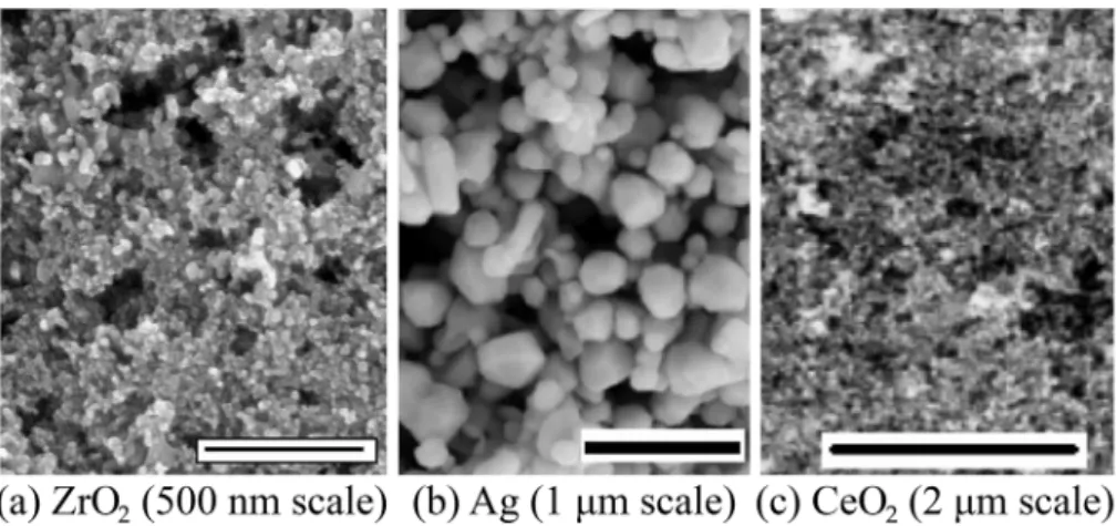
Fluoropolymer coatings impregnated with oxide and metal particles have drawn interest in the research community due to the ability to modify surface topology. Oxide and metal particles, such as ZrO2, Ag,
and CeO2, were mixed with Zonyl 8740 (a perfluoroalkyl methacrylic
copolymer) [31,51] to create the various coatings. The resulted surface morphology of different coatings is shown inFig. 11. Ice adhesion tests Fig. 7. Schematic of the different categories of icephobic coatings.
Fig. 8. Sintered PTFE coatings with gaps between the powder particles, imparting surface roughness. Figures reproduced from Ref. [42] with permission from Elsevier.
Fig. 9. Image of PVDF porous coating reproduced from Ref. [43] with per-mission from Elsevier.
Fig. 10. Image illustrating the textured surface of the fluorinated poly-dimethylsiloxane. Reproduced from Ref. [48] with permission from Elsevier.
were carried out by spraying supercooled water droplets (−10 °C, 2.5 g/m3LWC, 10 m/s wind speed and∼80 μm water droplet size) to
generate glaze ice. When tested using a centrifuge ice adhesion testing apparatus, the results showed that ice adhesion was reduced up to 5.7 times on a nano Ag modified surface [51], compared to the uncoated surface. However, as later found by the same research group, the coatings deteriorated quickly after several icing and de icing cycles as was exemplified by the increased bonding strength to ice (Fig. 12). This was attributed to surface roughness changes after cycling. The results from several of these studies further stress the importance that a coat ing's durability is vital, particularly under repeated icing and de icing conditions.
The examples provided here suggest that this class of materials can provide both superhydrophobic and icephobic capabilities. However, the durability of these coatings requires further improvement. 3.3.2. Polysiloxane based viscoelastic coatings
This class of polymer coatings is based on viscoelastic, low Tg sili cones. Silicones are polymers made of repeating units of siloxane along with functional constituents such as methyl, phenyl or trifluoropropyl. The low surface energy of the functional group bonds to the siloxane chain in combination with the low elastic modulus enables them to be icephobic [39].
From the perspective of reducing the adhesion of water to the solid surface, many researchers propose that a high contact angle in combi nation with a low sliding angle offer a reduction in water/ice adhesion to the surface [33,52]. As the bonding strength/energy between hy drogen atoms andfluorine atoms is three times greater than that of hydrogen atoms with dimethylsiloxane (or hydrocarbons) [33], many of the water/ice repellent coatings have been developed to make use of viscoelastic dimethylsiloxane polymeric materials. Indeed, viscoelastic coatings based on polydimethylsiloxane exhibited great ice adhesion reduction, near 100 times than that on a bare aluminium substrate [25]. The reduced ice adhesion was attributed to both the low surface energy and superior elasticity (perhaps to encourage interfacial sliding). This research also found that several existing so called “icephobic” wind turbine coatings had equivalent ice adhesion as that on bare aluminium surfaces. A plasma spray process was used to generate coatings from a liquid hexamethyldisiloxane feedstock (HMDSO, 98% purity, Aldrich) [53]. When applied onto an anodized aluminium surface, the coating could achieve an ARF of approximately four (from 400 to 100 kPa).
There are though several disadvantages associated with these
types of viscoelastic elastomer coatings; their bonding strength to non silica/glass substrates is poor, needing a primer as an interface [54], and the environmental resistance to dust, sand, and ice particles is in ferior to other coatings. Additives can be incorporated to render it more wear and erosion resistant, while at the same time imparting surface
roughness changes and superhydrophobicity. A coating manufactured using a mixture of tetraethyl orthosilicate and n octyltriethoxysilane with the addition of silica nanoparticles (functionalized with octyl
triethoxysilane) yielded a contact angle 153° [55]. Poly
dimethylsiloxane (PDMS) coatings with the incorporation of nano silica were developed to reduce ice accumulation on power line insulations [56]. Coatings were deposited using a sprayed gel process, with the resulting coating morphology shown inFig. 13.
PDMS coatings with nano silica particles of less than 100 nm in diameter were observed to exhibit superior ability in shedding water droplets, instead of allowing droplets to freeze upon impacting the surface [57], due to a high water contact angle of near 161° along with a low water roll off angle. The rate of ice accumulation was also re duced as a result. Under a supercooled water droplet spray condition, test samples held at−5 °C had negligible ice deposition for up to 0.5 h. The improved icephobic properties were attributed to both hydro phobicity and reduced ice adhesion to the coating. Similarly, other researchers also investigated the hydrophobic properties of PDMS with silica and PDMS with silica and metal oxides (Al2O3, Cr2O3, etc.) [58].
The addition of metal oxide was reported to impart a catalytic function to the reaction between the SiO2 particles and polymer. Other re
searchers developed transparent superhydrophobic coatings combining ZnO and SiO2with methylphenyl silicone binder [59]. An“erosion and
icephobicfluorosilicone coating” was marketed by AMES Shied [60]. Presumably, the erosion resistance is provided by the incorporation of particulates. Lastly, when using a composite coating structure with nano particles, it must be realized that the particle sizes for Fig. 11. Zonylfluoropolymer coatings with various surface topologies created by the incorporations of particulates. Figures reproduced from Refs. [31,51] re-spectively, with permission from Elsevier.
Fig. 12. Increase in coating-ice adhesion with each icing/de-icing cycle (the microstructure of sample A is shown inFig. 11(c). Figure reproduced from Ref. [31]) with permission from Elsevier.
superhydrophobic and icephobic coatings are in a different dimensional scale [57]. The selection of additives must be tailored for intended applications.
The long term stability of siloxane based icephobic coatings has not been well established. The plasma sprayed hexamethyldisiloxane re ported in Ref. [53] showed surface degradation after 15 cycles of icing/ de icing. Aluminium samples coated with perfluoro octyltriethox ysilane also experienced degradation in terms of its ice adhesion in crease and water repellency reduction [31]. The same study also found that “wet” samples, exposed to a condensation condition prior to an icing test, produced ice adhesion strength values as large as three times that of dry samples. Similarly, ice adhesion to coatings made of per fluorodecyltriethoxysilane (FAS 17) or stearic acid (SA) increased about four times after 20 cycles of icing and de icing [24]. Hydrolysis was considered as a probable reason when the coating was in contact with water or ice for long period of time. In another study, although limited hydrolysis of the siloxane bonds was observed, the contact angle and roll off angle were not significantly influenced after 100 cycles during a 250 h test [61].
3.3.3. Metallic coatings
Erosion from rain, sand, and dust particles is a critical issue for aerospace surfaces, thus coatings should have sufficient erosion re sistance to survive in the operating environment. Metallic coatings have become of interest, with some possessing icephobicity [62,63]. Tita nium based coatings are of particular interest with work done on tita nium nitride (TiN), titanium aluminium nitride (TiAlN), and commer cially pure titanium. In a study conducted by Palacios et al., TiAlN increased the erosion resistance of the leading edge erosion shield of a helicopter by two orders of magnitude [63]. The TiN samples also im proved the erosion resistance, however, they increased the ice adhesion strength when a performance metric that normalized the adhesion strength as a function of the roughness was introduced. The TiAlN samples had a lower ice adhesion strength than the titanium substrate when the roughness was below 0.6μm [64]. Although the roughness of the surface increases with usage, polishing the surface prior to initial commissioning will minimize the initial roughness and maximize the overall performance.
A study by Jung et al. tested a variety of icephobic, hydrophobic, and hydrophilic coatings and found that the hydrophilic diamond coatings yielded the greatest freezing delay time [65]. Although these surfaces are hydrophilic, their very low surface roughness (1.4 6 nm) is
near the critical ice nucleation radius, thus significantly delaying the freezing time. The critical ice nucleation radius is the critical size that an ice crystal must reach for freezing to occur. This low surface roughness ensures that ice cannot form within the asperities, leading to a low ice adhesion strength.
3.3.4. Surface texturing and topology modifications
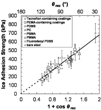
One study found that the ice adhesion to known,flat surfaces may have reached a physical limit [6]. This was observed from a large test matrix of samples, including 21 different materials with different water contact angles. As shown inFig. 14, the ice adhesion strength decreases as the receding contact angle increases. However, as no known material has a receding angle greater than 120° [6], it was suggested that any further reduction to ice adhesion beyond 150 kPa must be achieved by surface topology changes or polymer molecular engineering [39]. Based on observations of reduced ice adhesion with increased water contact angles, roughened surfaces that allow the entrapment of air within their asperities have been proposed as means to reduce ice adhesion. How ever, these structures, which are difficult and costly to manufacture, are prone to damage during cyclic icing and de icing processes as the na nofeatures may break off [24,66]. Furthermore, when the atmospheric humidity level is high, the nature of the roughened/textured surface can switch from a Cassie Baxter state with trapped air below the water droplet to a Wenzel state [19,67] of low water contact angles (< 90°). The following sections summarize several of these textured coatings/ surfaces with enhanced icephobicity, along their application methods. 3.3.4.1. Textured anodic aluminium surface. Aluminium alloys are commonly used to manufacture aircraft structural components. Even
with the wide spread use of composite materials and fibre metal
laminates, aluminium will remain a common substrate material to manufacturing aircraft. To prevent corrosion or accept paints, aluminium alloys are routinely anodized and primed. The existing anodizing processes, whether by sulphuric (SAA), phosphoric (PAA), or oxalic acid, may be coupled with anti icing features. Both SAA and PAA could generate a control pitched surface profile and render the surface hydrophobic after post processing with HDFS (Heptadecafluoro 1,1,2,2 Fig. 13. PDMS modified nano-silica hybrid coating that exhibits superior ice
accumulation resistance. Reproduced from Ref. [56] with permission from Taylor & Francis.
Fig. 14. Relationship between ice adhesion and receding contact angle where (1+cosθrec) is proportional to the practical work of adhesion. Figure
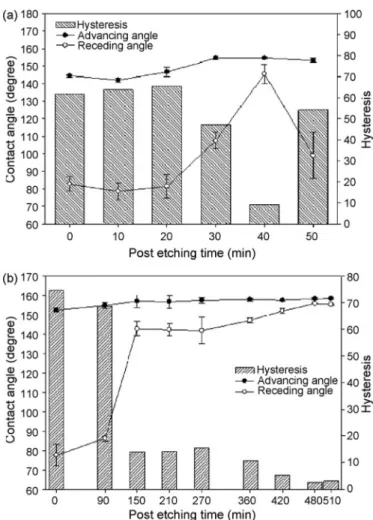
tetrahydrodecyl trichlorosilane) [68]. Examples of these nano surface structures are shown inFig. 15. The resulting contact angle changes from untreated states were significant, as shown in Fig. 16. Post anodizing processing with FOTS (fluorooctyltrichlorosilane) hexane treatment can render the anodized surface superhydrophobic, as the reported contact angles were greater than 150° [69].
However, when utilizing surface texture for anti icing purposes, it must be employed judiciously as a groove with a characteristic width ranging from 0.1 nm to 2 nm may promote ice crystal nucleation [70]. 3.3.4.2. Laser texturing. A laser has the potential to micromachine any surface. With the wide spread use of lasers in processing and potentially in additive manufacturing, the use of laser profiling to create icephobic surfaces is appealing from the perspective of manufacturability and durability. One study showed that laser texturing had the ability to impart icephobicity to both metal substrates and diamond like carbon (DLC) coatings [71]. The surface morphology of the DLC coating is shown inFig. 17.
Laser texturing was also used to create a hydrophobic titanium (Ti) surface. Here a pulsed ultrafast laser micro texturing process was em ployed as shown inFig. 18 (a) and the result was a Ti surface with pillars several microns in height (Fig. 18(b)) [72]. After laser proces sing, a thin fluoropolymer coating was applied to achieve a contact angle of 165° and a sliding contact angle of < 7°. Linear abrasive wear test results indicated that the laser processed surface can maintain a contact angle > 150° after three abrasion cycles using a 350 g mass (108 kPa applied pressure). Some superficial wear occurred due to the fracture of the upper 10% of the pillars, again illustrating the im portance of suitable mechanical durability for harsh application con ditions.
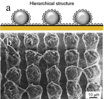
3.3.4.3. Two tiered surface structuring. A polymer, whether it isflat or contoured, can be implanted with particles to create bimodal surfaces containing micro and nano structure. Illustrated here are two of such structures; one engineered with two sizes of silica particles (10 nm and 50 nm) and the other with lithography followed by spraying 10 nm silica particles dispersed in epoxy, as shown in Fig. 19(a) and (b), respectively. Epoxy is used in many aircraft composite systems; the attachment of surface features into the epoxy matrix has the potential to be part of the composite manufacturing process. Micro and nano sized silica in an epoxy matrix provided hydrophobicity, while at the same time improving wear resistance [73]. The resulting hierarchical surface structures (Fig. 19) with bimodal features render the surface capable of de icing, self cleaning and anti fouling. However, it is not clear if this coating structure can sustain anti icing characteristics under a high humidity environment as the increased surface area, once covered by frost, may result in increased ice adhesion. In addition, the resistance to abrasive wear is not known.
In another study, a micro scaled surface was createdfirst with a wet etching process to generate cones about 60μm apart; the surface was
then etched with deep reactive ion etching (DRIE) to grow“grass” on the entire surface, as show inFig. 20. Finally, the profiled surface was
coated with perfluorooctyl trichlorosilane (in hexane solution). The resulting surface was tested under 65% relative humidity (at an am bient temperature of 22 °C) with samples cooled to a temperature of −10 °C using a cooling stage [74]. Based on a detailed in situ frost formation observation, it was concluded that the engineered structure was able to retard the frost formation process through a higher energy barrier for droplet coalescence and nucleation.
A similar structure containing micro meter pillars (fabricated with photolithography and cryogenic ICP etching) with nano scaled surface roughness (PECVD SiO2followed by ICP etching) and afinal layer of
Fig. 15. SEM images of (a) PAA (360 min of etching) and (b) SAA surface (30 min of etching). Figures reproduced from Ref. [68] with permission from Elsevier. Fig. 16. Contact angle and hysteresis changes. (a) HDFS treated SAA and (b) HDFS treated PAA. Figures reproduced from Ref. [68] with permission from Elsevier.
perfluorodecyltrichlorosilane (FETS) [75] has shown that the freezing delay of a sessile supercooled water droplet at−21 °C is up to 25 h. The authors attributed this long nucleation delay (longest based on litera ture) to the presence of an interfacial quasi liquid layer.
Despite the exceptional anti icing and hydrophobic properties of these highly engineered surfaces, one must be aware of the effect of surface roughness under various icing conditions. Certain roughened surfaces can accelerate the heterogeneous nucleation of ice while others may increase the ice adhesion strength. A review written by Schutzius et al. revealed that for a multi tier surface structure, each roughness scale must address a specific target; the micro scale has a low adhesion strength while the nano scale texture resists droplet impingement and promotes rebound [76]. Additionally, the processes used to create these surfaces, such as photolithography, CVD, PVD, etc., are costly and not suitable for mass production or on large structures.
3.3.4.4. Textured and coated stainless steels. Stainless steels are used to house many aircraft instruments and gauges; anti icing ability is also beneficial for many applications. Here a simple chemical etching (50% FeCl3 solution) followed by the deposition of a layer of nano silica
dispersed in methoxy silane has rendered a stainless steel icephobic, based on qualitative outdoor snow and freezing rain test [61]. In particular, the treated surface was able to sustain a water contact angle of 155° after 100 icing/de icing cycles and a cavitation erosion simulation test.
3.3.5. Liquidfilled porous surfaces
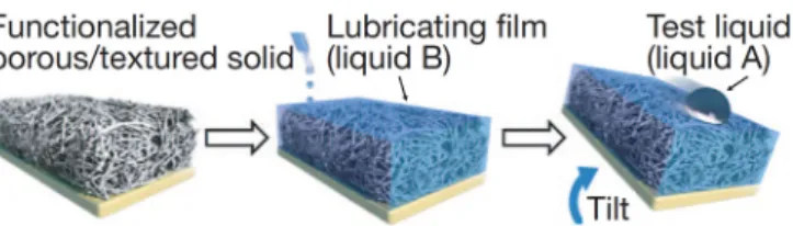
3.3.5.1. Slippery Liquid Infused Porous Surfaces (SLIPS). Inspired by
plants and insects in nature, a class of Slippery Liquid Infused Porous Surfaces (SLIPS) has been created by several researchers [34,77,78]. To overcome the deficiency of hydrophobic surfaces in a moisture saturated environment (due to frost formation), a new composite surface design was created to minimize the frost formation on the surface. In this design, shown in Fig. 21, a nano porous polymer structure was first fabricated using electrodeposition; it was then followed by the infiltration of a low freezing point fluorinated liquid. The liquid is retained on the surface by the nano structure, giving the surface a“slippery” nature [34]. In fact, a pitcher plant has a similar slippery liquidfilled porous structure. Both of which rely on the simple fact that the smoothest surface is a liquid. This engineered composite structure has a combination of low contact angle hysteresis (for water droplets to roll off the surface) and low ice adhesion of 16 kPa [41]. Despite the superior icephobic properties, lubricant depletion would occur and compromise the performance.
3.3.5.2. A lubricant infused electrospray silicone rubber anti icing
coating. In this study, a heptadecafluorodecyltrimethoxysilane
fluorinated coating was fabricated to exhibit a hierarchically porous structure [79]. This structure was designed with the objective to improve upon the existing SLIPS [34] so that ice nucleation can be delayed for a longer duration and the period prior to lubricant depletion
extended. The porous structure was infiltrated with a
perfluoropolyether lubricant. The results showed that the ice Fig. 17. SEM image of laser profiled DLC. Reproduced from Ref. [71] with
permission from Elsevier.
Fig. 18. Laser micro-texturing process (a) and the resulted surface morphology (b). Figures reproduced from Ref. [72] with permission from IOP Science. Fig. 19. Bimodal surface structures consisting of (a) two powder particle sizes and (b) surface structure created with lithography and spraying of nano-sized silica. Figures reproduced from Ref. [73] with permission from Elsevier.
adhesion strength can be reduced to 60 kPa (vs 1400 kPa for the uncoated substrate). However, this value increased to 600 kPa after 20 cycles of frosting and defrosting (the frosting process was carried out at−14 °C in an environment with 80 90% humidity; after the surface was covered with frost the temperature was raised to room temperature and then the cycle repeated). The degradation was due to the loss of lubricant with each cycle. Based on a similar principle, others showed a silicone oil infused polydimethylsiloxane coating achieved a low ice adhesion of 50 kPa (3% of that of bare aluminium) [80]. Similarly, in another study of an oil infused porous PDMS coating, the ice adhesion strength was reduced to 38 kPa, about 50% the ice adhesion strength of
a smooth PDMS surface and∼30% of micro featured PDMS surface
shown inFig. 22[81].
3.3.5.3. Antifreeze releasing coatings. A bioinspired coating was reported in Ref. [82] where a porous superhydrophobic layer with wicking channels was embedded. These channels were then infiltrated with antifreeze agent. Tests in frosting, simulated freezing fog, and freezing rain showed that the onset of either frost, rime or glaze ice formation was delayed for at least 10 times longer than that of other coating systems, including the lubricantfilled surfaces. Depending upon how easily the antifreeze agent can be replenished during service, it has a potential aircraft application since the antifreeze agent is regularly applied to aircraft in icing conditions before taking off.
The latest, commercially available room temperature vulcanizing (RTV) R 1009 (Nusil Sol Gel Vulcanized Silicone Coating) has seen an ice adhesionfive times less than the previously marked anti icing coating R 2180 [83], also developed by the company [84]. The comparison of NuSil R 2180 with other commercial coatings is illustrated inFig. 23. Although not being disclosed in public, it was speculated that this series of vulcanized coatings contains a slow releasing agent of freezing point depressant [6]. The authors of this paper are currently investigating the use of silicone R 1009 in conjunction with piezoelectric actuators in a hybrid coating/ultrasonic de icing system.
Among all types of anti icing coatings described in this section, the lowest ice adhesion was reported among the SLIPS category of coatings [39]; at 16 kPa, the ice adhesion on these surfaces is nearly two orders of magnitude lower than that on uncoated aluminium surfaces. In terms of the durability of these coatings, as the liquid (lubricant, oil or anti freezing agent) is held in place via weak capillary force, its depletion or
dilution, particularly during repeated icing/de icing, is likely to occur, thus rendering the coatings non functional if an active charging system is not put in place [15].
3.3.6. Icephobic polymer coatings designed based on cross link density and interfacial lubricant
The newest and perhaps the most advanced icephobic coating series were designed to enable polymer chain mobility within an elastomer matrix, hence creating a slip boundary condition between the ice and coating surface [39]. As the shear stress to cause slip at the interface is
governed by τ=Gfa/kT (where G is the physical stiffness or shear
modulus under isotropic conditions, f is the force needed to detach a single chain with a length, k is the Boltzmann's constant, and T is the temperature) and the polymer cross link densityρCL. The authors pro
posed two methods to reduce the adhesion of ice on a polymer surface by (1) using a polymer with low cross link density and (2) the addition of miscible lubricant to enable interfacial slippage. Using the first method, a low cross link density PDMS was able to arrive at a low shear strength of 33 kPa, without the addition of lubricants nor the presence of texture/roughness. With the addition of interfacial lubricants (such as silicone, krytox or oil) into the polymer structure chemically (vs. physical infiltration in SLIPS), the adhesion strength was further re duced to 6 kPa. Other polymer systems (polyurethane (PU),fluorinated polyurethane (FPU), and PFPE, shown inFig. 24) also exhibited similar improvements with cross link density reduction, although the addition of an interfacial lubricant had a greater impact on the ice adhesion reduction. Furthermore, when these engineered icephobic coatings were subjected to repeated icing/de icing cycles, wear, and outdoor weathering, they consistently demonstrated superior durability to commercially available (Nusil, NeverWet) and SLIPS coatings. Fig. 20. SEM images of a two-tiered surface structure. The diameter of the“grass” is about 300 nm. Figures amended and reproduced from Ref. [74], published under a Creative Commons Attribution 3.0 Unported License.
Fig. 21. Illustration of the SLIPS structure in which liquid infiltrated into a porous surface layer, enabling the solid surface to be perfectlyflat and saturated with liquid. Reproduced from Ref. [34] with permission from Springer Nature.
Fig. 22. Slippery liquid-infused porous surfaces (SLIPS) with an optimal com-bination of high water repellency and icephobicity. Reproduced from Ref. [81] with permission from American Chemical Society.
3.3.7. Carbon nanotube and graphene containing coatings
In terms of durability and electrical properties required for potential aircraft applications, carbon nanotube (CNT) and graphene may pro vide the needed physical/mechanical properties, and offer a practical way to modify the surface topology and impart hydrophobicity and perhaps icephobicity. Although not being tested for anti icing, a CNT forest structure was fabricated with vertically aligned nanotubes (CNTs) within a PTFE matrix [85]. A micrometre scaled water droplet was completely suspended on top of this surface as shown inFig. 25. In another study, a composite epoxy resin, impregnated with CNTs, was sprayed onto a substrate and superhydrophobicity was reported [86]. The use of nanotubes in a coating provides an opportunity to in corporate heating into the surface for de icing and anti icing purposes. In fact, resistance heating was enabled in afilm of graphene nanoribbon (with large aspect ratio to form electrical pathway) within an epoxy matrix [87].
Unlike that discussed in the preceding sections where coatings were intended to provide reduced ice adhesion and delayed freezing of su percooled water droplets, one coating developed for protecting aircraft radomes was based on an active mechanism where current is passed through the layer to generate heat for de icing [88]. In this research, graphene nanoribbons (GNRs) coating (100 nm), which is transparent to radio frequencies, was applied to substrate using an airbrush at 220 °C. A de icing test was carried out at −20 °C and successful ice removal was reported. In another report, a Carbo e Therm coating was applied on curved surfaces and it could be electrically heated for use in the non hazardous low voltage range (e.g. 12/24 V). It contains carbon nanotubes and graphite to render it electrically conductive [89]. By
Fig. 23. Laboratory ice adhesion test results of R-2180 and several other commercial icephobic coatings. Reproduced from Ref. [128] with permission from CRREL.
Fig. 24. Ice adhesion strength is demonstrated as a function of cross-link density, (a) With interfacial slippage and (b) without interfacial slippage. Figures re-produced from Ref. [39] with permission from AAAS.
Fig. 25. (a) SEM image of a carbon nanotube forest coated with PTFE and (b) water droplet suspends on top of the surface. Figures reproduced from Ref. [85] with permission from American Chemical Society.
combining icephobic coatings with conductive additives, the result is a coating with both passive and active anti icing and de icing cap abilities. Lastly, the approach used in SLIPS can be incorporated into these functional coatings; an example of which is a spray coated per fluorododecylated graphene nanoribbons with the addition of a lu bricating slippery surface [90].
3.3.8. Other coating types
A negatively charged surface has been reported to have the function of reducing freezing temperature, in particular, a textured hydrophobic stainless with anionic polyelectrolytes brushes was found to reduce the freezing temperature by at least 7 °C than that measured on untreated surface [91]. Coating material with polarity changes (generated for example by an externally applied electric field during the coating process) also has the effect of reducing the freezing temperature of water on the surface by restricting heterogeneous ice nucleation [67]. Ultimately, if a coating can be developed to delay the freezing of su percooled water droplets to beyond−50 °C, icing may no longer pre sent an issue during high altitudeflight.
Icephobicity can also be combined with other functions such as aircraft drag reduction. From the study of many living species, it has been realized that many surfaces have the natural ability to repel water (lotus leaf, pitcher plant, cicada, etc.) and also possess superior aero dynamic performance (butterfly wings and shark skin, as shown in
Fig. 26) [92,93]. In fact, shark skin topology can help reduce drag by up to 8% and fuel consumption by 1.5%, not to mention that it possesses the needed surface topology for potential icephobic properties.
Also inspired by nature, another development in this area is the creation of biological antifreeze proteins. This is a new and different area that may see future development of synthetic macromolecules for preventing ice crystals from growing [94]. A detailed review can be found in the quoted reference.
4. Harmonization of tests for assessing the durability of functional icephobic coatings
The benefits expected from the use of icephobic coatings are to limit ice accretion on an aircraft surface duringflight in icing conditions or to facilitate ice shedding on rotating components or components exposed to aerodynamic shear forces. When combined with an active IPS (heating elements, mechanical actuators, surface acoustic wave actua tors, piezoceramic actuators, etc.), the technology should reduce the energy consumption of the overall IPS.
To be applied onto aircraft, icephobic coatings must meet several major requirements including but not limited to, erosion resistance (rain, sand), chemical exposure tolerances, resistance to UV exposure and thermal shocks, remain operative in representative icing flight conditions (e.g., 25 FAR Apps. C, O, or P), comply with the latest REACH (Registration, Evaluation, Authorisation and Restriction of Chemicals) regulations [95], and be compatible with all existing air craft (engine/airframe/nacelle) surfacefinish requirements.
4.1. Preliminary tests on as manufactured icephobic coatings
4.1.1. Contact angle, surface roughness, elasticity, coating thickness and FT IR analysis
To verify the properties of an icephobic coating, a series of tests must be performed to determine the wettability via water contact angle measurements, the surface roughness, the elasticity (when applicable, e.g. via nano indentation measurements), the thickness of the coating (e.g., via eddy current measurements), and a surface spectroscopic analysis (e.g., FT IR or surface Raman) for controlling surface chemistry and cleanliness of the samples.
4.1.2. Ice adhesion strength, cross cut & REACH compliance
The ice adhesion strength must be determined using one of several methods currently used in several labs (e.g., tensile mode (Mode I), shear mode (Mode II), rotating arm, or bending test) in well defined, simulated atmospheric icing conditions in icing wind tunnel tests (IWTT). Since not all conditions can be tested, a design of experiments (DoE) approach can be employed for selecting a reduced number of icing parameters that are most representative of atmospheric icing, e.g. including a rime, a glaze, and two mixed icing conditions outlined in
Table 3[96,97].
Cross cut adhesion tests [98] of the coatings to the substrates can be performed according to the ISO 2409 procedure only on polymer coatings. The test is not applicable to icephobic functionalized metals or ceramic materials, which are used either bare or the coating applied (like, PFPE or perfluorinated silanes or siloxanes) is only a mono molecular thick polymerfilm and as such, its adhesion to the substrate is not detectable by the cross cut test.
REACH compliance must be assessed for all icephobic coatings ac cording to the regulation.
4.1.3. Rain erosion testing
Rain erosion resistance must be tested according to well defined and accepted standards for aerospace applications, such as the P JET or the whirling arm tests which run according to the standard DEF STAN 00 35 [99]. A set of representative testing conditions is listed inTable 4. The working principle of the P JET, developed at Airbus, is that a jet of water accelerated by a pump to a set velocity is chopped into short segments by a disc with two openings rotating at a set speed. The front heads of the water segments acquire a hemispherical shape due to surface tension and aerodynamic drag. The segments then impinge on the surface of the test coupon that can be tilted at a desired angle of incidence. The number of impact events at the same location can be varied depending on the need and the type of coating: for our purposes, the number of impacts was varied between 20 and 3000. The testing schematic is shown inFig. 27while results of the droplet impact on several surfaces is shown inFig. 28.
4.1.4. Sand erosion testing
Sand erosion resistance must be tested according to well defined and
accepted standards for aerospace applications, such as ASTM standard G76 04 [100] which is used for the Plint TE 68 Gas Jet Erosion Rig. A set of representative parameters for this test is listed inTable 5.
The working principle is that a defined mass of sand particles is suspended in theflow of a carrier gas and accelerated towards a nozzle that directs the mixed stream of gas and particles towards the sample surface as outlined inFig. 29. After having eroded the sample with a defined mass of sand (erodent), the weight loss of the sample is de termined (eroded mass), and the test continues. The test is stopped when the maximum mass of erodent has been applied or when the coating is fully eroded and the primer or the substrate become exposed. During the sand erosion test, different surfaces will exhibit different behaviours. For example, elastomers undergo slow deformation while the sand particles accumulate and will suddenly fail, rendering the coating useless. On the other hand, polymers erode linearly with in creasing erodent mass while functionalized metallic surfaces typically show no visible damage until the metal itself is eroded.
4.2. Functional performance of icephobic coatings
After having discussed how to assess the basic properties of ice phobic coatings, we want to introduce an example of how to assess the functional performance of icephobic coatings. Functional performance testing investigates how the icephobic properties of the coatings dete riorate during (simulated) operation. This analysis goes one step be yond that of the previous section that investigated the durability of the coatings themselves; here it is intended to assess the durability of the icephobic property.
4.2.1. Preliminary considerations
Thefirst consideration to be made is that there is, so far, no es tablished standard known to us for testing the functional durability of icephobic coatings, meaning the durability of the coating itself and the durability of its functionality in relevant (simulated) environmental conditions. One thus needs to define a new set of tests and measurables that allow for a meaningful and reliable assessment. The following so lutions could offer viable alternatives:
•
Solution 1: Expose all samples to sequential degradation tests (erosion, UV, thermal,fluids, etc.) and after each step determine the ice adhesion strength in an IWTT•
Solution 2: Simulate accelerated degradation (erosion, UV, thermal, fluids, etc.) over the whole sample area and perform wettability tests only (contact angles of water drops) on the degraded coatings, taking the degradation of surface wettability as a strong indicator for adhesion strength to iceSolution 1 is very expensive and time consuming while solution 2 is less costly and time consuming, but might provide only an incomplete set of results. Therefore, there is a strong need of defining a more rapid, but complete screening standard for functional tests in the future. 4.2.2. Simulation of mechanical degradation
For the mechanical degradation simulations, a sandblasting test can be used to simulate erosion and a measurement protocol can be de veloped. The discrete time steps of sandblasting by which the thickness of the coating is gradually reduced would need to be standardized. These time steps depend on the specific material of the coating and must be found empirically. After each time step, the CA and the RoA of water drops on the surface must be determined.
We must point out here that, since there are no existing ISO guidelines or standards to follow for such a characterization, the mea surement protocol must be set up and the sandblasting parameters chosen according to a best practice that must be developed during the course of the testing.
4.2.3. Simulation of physical chemical degradation
For simulating chemical degradation and stability, one must per form Q UV tests, immersion in at least two referencefluids, e.g. Skydrol Table 3
Reduced set of four representative icing conditions that can be selected for ice adhesion tests.
Ice type Total air temperature (TAT) [°C] Airspeed [m/s] Liquid water content (LWC) [g/cm3] Mean effective droplet diameter (MVD) [μm]
Rime 20 50 0.3 20
Mixed/rime 5 50 0.3 20
Mixed/glaze 20 50 0.8 20
Glaze 5 50 1.0 20
Table 4
Example of DEF STAN 00-35 rain erosion testing parameters used with P-JET.
Velocity (m/s) 225
Drop size (mm) 2
Disc rotational frequency (Hz) 20
Nozzle diameter (mm) 0.8
Sample-to-nozzle distance (mm) 60
Impact angle (°) 90
Test sequence (no. of drops) 20→ 50 → 100 → 250 → 500 → 1000 →
2000→ 3000
Fig. 27. (left) Testing program showing the array of drops impacting a test coupon; (right) working principle of the rain erosion test rig P-JET: a continuous water jet is cut into short segments by a rotating mechanical chopper disc.
(hydraulicfluid) and Kilfrost (de icing fluid), and a thermal treatment. The Q UV irradiation parameters that can be used are an intensity of 40 W at a wavelength of 313 nm, based on ISO standard 164746. As for the two representativefluids chosen for immersion tests, the Kilfrost im mersion temperature could be T = 23°C for a maximal immersion time of 7 d, while the Skydrol immersion temperature could be T = 70°C for a maximal immersion time of 48h. Thermal treatment parameters that can be used are a temperature, T = 90°C for a time of 100 hours. 4.3. Concluding remarks on testing of icephobic coatings
As a general conclusion to this paragraph it must be stated that novel functional coatings, to which icephobic coatings belong, will be used on future laminar aircraft designs for increasing performance, decreasing fuel consumption, or reducing maintenance. To assess their performance and durability, new test methods must be developed in a
common effort among all interested academic, industrial, and reg ulatory partners. Thefirst outcome of such a joint effort will be har monized testing guidelines, while thefinal goal must be to define new industrial standards.
5. Hybrid Icephobic coating/active anti-icing and de-icing strategies
Despite the ongoing research efforts on designing and manu facturing icephobic coatings, coatings alone may not be sufficient for aircraft de icing and anti icing needs. In early work carried out by Anderson [101], it was concluded that ice accumulation in an IWTT or inflight conditions is largely dependent upon the external environment, not the surface itself. It went on further to state that as soon as a thin layer of ice was formed, the coating would no longer be functional. There is currently no universal coating solution [102] to resist ice formation under a wide variety of icing conditions and formation modes, including the fully wetted state under the conditions of high
speed water droplet (with higher Weber number We =ρV2R/γ) im
pingement and condensation from moist environments [6]. Further more, many polymer based coatings have shown substantial dete
rioration after repeated icing/de icing cycles: hydrolysis of
fluorooxysilane based coatings (one of the most researched coating bases) contributes to coating degradation; mechanical stresses during icing/de icing cycles compromise the surface asperities [103], hence Fig. 28. Rain erosion results for three coupons. From left to right: an elastomer coating showing heavy delamination, polyurethane coating showing local damage increasing with number of drop impacts, and a functionalized metallic surface showing no visible damage.
Table 5
Example of ASTMG76sand erosion testing parameters.
Velocity (m/s) 50–65 (270 mbar pressure at nozzle)
Particle size (μm) 250–270 (nearly spherical silica particles)
Discharge rate (g/min) 2
Sample-to-nozzle distance (mm) 20
Impact angle (°) 20
Test sequence (g) 0→ 5 → 10 → 20 → 50 → 100 → 150 → 200