DOCTORAT DE L'UNIVERSITÉ DE TOULOUSE
Délivré par :
Institut National Polytechnique de Toulouse (INP Toulouse)
Discipline ou spécialité :
Conception des Circuits Microélectroniques et Microsystèmes (CCMM)
Présentée et soutenue par :
M. PATRICE NOUVEL
le mercredi 18 décembre 2013
Titre :
Unité de recherche :
Ecole doctorale :
CONCEPTION D'UN SYSTEME DE VERROUILLAGE SUR DE
FONCTIONNEMENT POUR LES COLLISIONNEURS LINEAIRES.
Génie Electrique, Electronique, Télécommunications (GEET)
Laboratoire d'Analyse et d'Architecture des Systèmes (L.A.A.S.)
Directeur(s) de Thèse :
MME HÉLÈNE TAP -BETEILLE M. BRUNO PUCCIO
Rapporteurs :
M. LIONEL TORRES, UNIVERSITE MONTPELLIER 2 M. YANNICK HERVE, UNIVERSITE STRASBOURG 1
Membre(s) du jury :
1 M. JEAN ARLAT, LAAS TOULOUSE, Président
Abstract
Doctoral School
Génie Electrique, Electronique, Télécommunications
DOCTORAT DE L’UNIVERSITÉ DE TOULOUSE
Design of a dependable Interlock System for linear colliders
by Patrice Nouvel
For high energy accelerators, the interlock system is a key part of the machine protection. The interlock principle is to inhibit the beam either on failure of critical equipment and/or on low beam quality evaluation. The dependability of such a system is the most critical parameter. This thesis presents the design of an dependable interlock system for linear collider with an application to the CLIC (Compact Linear Collider) project. This design process is based on the IEEE 1220 standard and is is divided in four steps. First, the specifications are established, with a focus on the dependability, more precisely the reliability and the availability of the system. The second step is the design proposal based on a functional analysis, the CLIC and interfaced systems architecture. Third, the feasibility study is performed, applying the concepts in an accelerator facility. Finally, the last step is the hardware verification. Its aim is to prove that the proposed design is able to reach the requirements.
Resumé
Ecole Doctorale
Génie Electrique, Electronique, Télécommunications
DOCTORAT DE L’UNIVERSITÉ DE TOULOUSE
Conception d’un système de verrouillage sûr de fonctionnement pour les collisionneurs linéaires
par Patrice Nouvel
Pour les accélérateurs de particules à hautes énergies, le système de verrouillage est une partie clé de la protection de la machine. Le verrouillage de la machine est l’inhibition du faisceau dès lors qu’un équipement critique tombe en panne et/ou qu’un faisceau est de faible qualité. Pour un système de verrouillage, sa sûreté de fonctionnement est la caractéristique la plus importante. Cette thèse présente le développement d’un système de verrouillage pour les collisionneurs linéaires avec une application au projet CLIC (Compact Linear Collider). Son élaboration s’appuie sur la norme d’ingénierie IEEE 1220 et se décline en quatre parties. Tout d’abord, les spécifications sont établies. Une attention particulière est portée sur la sûreté de fonctionnement, plus précisément, la fiabilité et la disponibilité du système. La deuxième étape est la proposition d’un design. Celui-ci est basé sur une analyse fonctionnelle, les interfaces du système et l’architecture du CLIC. Troisièmement, une étude de faisabilité est effectuée en appliquant les concepts dans un environnement opérationnel. Finalement, la dernière étape est la vérification matérielle. Le but est de prouver que le design proposé est capable de remplir le cahier des charges établi.
First of all, I would like to thank the rapporteurs Lionel Torres and Yannick Herve for their valuable advices and the time they spent to read this manuscript.
I would like to warmly thanks my thesis director, Hélène Tap, for her precious guidance which leads me successfully to the thesis defence. A big thanks to Bruno Puccio, my CERN supervisor, who gives me the opportunity to undertaken this PhD. His support, advices and availability during these 3 past years have been a key factor to the thesis success.
I would like to thank Alexey Dubrovskiy for his help for the CTF3 application. For their help on the dependability study, I would like to thank Benjamin Todd and Sigrid Wagner. For their help on JAVA programming, Maxime Audrain, Rafal Leszko and Jean-Christophe Garnier (and for his help for Linux).
Also, I would like to thank Bernard Collignon and Chistophe Martin for their help on the test bench realisation.
I would like also to thank Andrzej Siemko, the group leader, to allow me to present my works in conferences.
A big thank to the (not yet cited) lunch (and ping pong) and machine interlock team : Ivan, Jakub, Jacek, Andrea, Stephane, Konstatinos, Javier, Daniel, Damien, Scott, Gae-tan, Steffen, James, Jonathan, Cristina, KajeGae-tan, Dawn, Alain, Jean-Louis, Jean-Phillipe, Jeremie, Pierre, Juan, Maciej, Markus, Kamil (with the hope I did not forget anybody).
In more general way, I thank my friends, who were tolerant enough to allow me talking about the PhD !
More personally, I thank my family, for their help (special mention to Jeff, who gives me regularly a place to rest myself). At last but not the least, I thank Claire for her constant support on a day basis for this challenge !
Abstract 3
Acknowledgements 5
List of Figures 11
List of Tables 15
1 General Introduction 1
2 Context and state of the art 5
2.1 Introduction . . . 5
2.2 Particle Physics and CERN . . . 5
2.2.1 Challenges in particle physics . . . 6
2.2.2 European Organisation for the Nuclear Research . . . 8
2.3 High energy linear colliders overview . . . 10
2.3.1 CLIC overview . . . 10
2.3.2 ILC overview . . . 14
2.3.3 CLIC and ILC parameters comparison . . . 18
2.4 CLIC Machine protection overview . . . 18
2.4.1 Failures type and protection strategies . . . 19
2.4.2 Machine Protection Systems . . . 20
2.5 CLIC Interlock system and thesis problematic . . . 21
2.5.1 Beam Permit . . . 21
2.5.2 Post-pulse analysis . . . 21
2.5.3 Thesis problematic definition . . . 22
2.6 Introduction to interlock systems . . . 23
2.6.1 Protect the machine - Beam Interlock Function . . . 23
2.6.2 High dependability requirements . . . 24
2.6.3 Common design . . . 25
2.7 Selected protection systems . . . 26
2.7.1 LHC Beam Interlock System . . . 26
2.7.2 Linac Coherent Light Source Interlock System . . . 28
2.7.3 Linac 4 watchdog . . . 29
2.7.4 Real-time and post-pulse beam quality assessment for LHC beams 30 2.7.5 Safe Machine Parameters . . . 31
2.8 Conclusion . . . 33
3 Requirements establishment 35 3.1 Introduction . . . 35
3.2 Operational scenarios and interfaces . . . 36
3.3 Functional requirements . . . 38
3.3.1 Main functional requirements . . . 39
3.3.2 Functional suggestions . . . 40
3.4 Performance requirements . . . 40
3.4.1 Response times . . . 40
3.4.2 Establishing dependability requirements . . . 41
3.4.3 Reaching dependability requirements . . . 46
3.4.4 Suggestions for the dependability study . . . 49
3.5 Interfaces and safety-critical requirements . . . 50
3.5.1 Acquisition and control infrastructure . . . 50
3.5.2 Target systems . . . 53
3.6 Conclusion . . . 55
4 Design Proposal 57 4.1 Introduction . . . 57
4.2 Functional analysis . . . 57
4.2.1 System functional behaviour . . . 58
4.2.2 Functional decomposition . . . 58 4.2.3 Functional architecture . . . 65 4.3 Implementation proposal . . . 66 4.3.1 Subfunctions implementation . . . 66 4.3.2 System implementation . . . 68 4.3.3 Hardware modules . . . 71 4.4 Conclusion . . . 73 5 Design verification 75 5.1 Introduction . . . 75 5.2 Feasibility study . . . 75 5.2.1 Operational context . . . 76 5.2.2 Experiment . . . 77 5.2.3 Technical description . . . 79
5.2.4 Results and discussion . . . 83
5.3 Hardware demonstration . . . 85
5.3.1 Technical discussion . . . 86
5.3.2 Goals . . . 87
5.3.3 VHDL blocks description . . . 87
5.3.4 Nodes description . . . 97
5.3.5 Hardware and test bench description . . . 99
5.3.6 Results and discussion . . . 106
5.4 Conclusion . . . 112
A Dependability data 117
B CTF3 Application details 119
B.1 Technical Overview . . . 119
B.2 Finite state machine diagram . . . 121
B.3 Threshold dynamic factors . . . 121
B.3.1 Maximum Value . . . 123
B.3.2 Beam Length . . . 124
B.3.3 Beam Charge . . . 124
C Hardware demonstration details 127 C.1 VHDL blocks details . . . 127
C.2 VHDL code extracts . . . 129
D Research trails for the CLIC Interlock System 133 D.1 Beam quality . . . 133
D.2 Interlock System and beam operation . . . 133
D.3 Interlock System and injection complex . . . 134
D.4 Interlock System and radiation . . . 135
D.5 Interlock System and acquisition infrastructure . . . 136
D.6 Local rules for global analysis . . . 139
E Requirements and constraints list 141 E.1 Requirements list . . . 141
E.2 Environment constraints list . . . 142
E.3 External requirements list . . . 142
F Conferences and workshops 143
Glossary and acronyms 145
2.1 Standard model particles common representation . . . 7
2.2 CERN accelerators complex . . . 9
2.3 CMS Higgs Search - collision electrons/muons at 8 TeV . . . 9
2.4 CLIC detectors push-pull scheme [1] . . . 11
2.5 Schematic overview of the CLIC layout . . . 12
2.6 Illustration of two beam accelerating scheme . . . 13
2.7 Simulation of a Higgs decay at ILC detector (courtesy to Norman Graf) . 15 2.8 Schematic overview of the ILC layout [2] . . . 16
2.9 Schematic the ILC cryomodule [2] . . . 17
2.10 ILC Detectors - SiD (left) and ILD (right) [2] . . . 17
2.11 Beam permit concept . . . 22
2.12 Typical system life cycle [3] . . . 22
2.13 Generic Interlock System overview [4] . . . 25
2.14 LHC BIS response time requirement [5] . . . 27
2.15 LHC BIS architecture . . . 27
2.16 LHC BIS Node synoptic view . . . 28
2.17 LCLS Interlock System Architecture [6] . . . 29
2.18 Linac 4 Watchdog implementation example . . . 30
2.19 Safe Machine Parameter Overview [7] . . . 32
3.1 Machine interlocking critical path . . . 37
3.2 The CLIC middleware architecture . . . 38
3.3 Interlock System interfaces synthesis . . . 39
3.4 Post-pulse analysis response time requirement . . . 41
3.5 Hazard Chain for Interlock System . . . 43
3.6 CLIC Interlock System overview . . . 47
3.7 Architecture model . . . 47
3.8 CLIC module [8] . . . 50
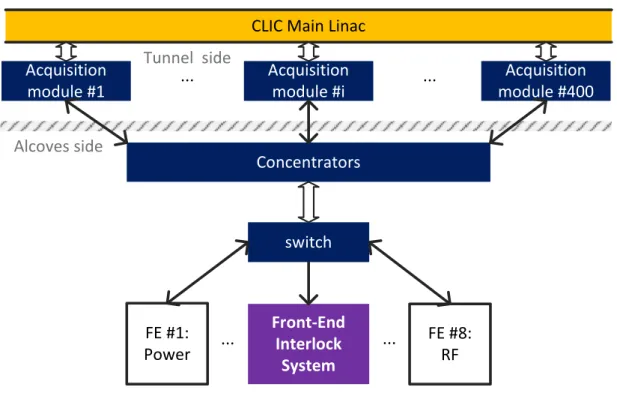
3.9 Acquisition and control infrastructure architecture . . . 51
3.10 CLIC Damping rings and extraction kickers . . . 54
3.11 Damping rings dump system [9] . . . 54
4.1 Interlock System functional black box . . . 58
4.2 Individual data analysis functional black box . . . 59
4.3 Global analysis functional black box . . . 60
4.4 Beam permit system functional black box . . . 61
4.5 Control system functional black box . . . 61
4.6 Functional time line and data flow - critical equipment input . . . 62 9
4.7 Functional time line and data flow - Beam quality input . . . 62
4.8 Functional time line and control flow . . . 63
4.9 Functional architecture schematic . . . 65
4.10 Beam permit loop implementation . . . 67
4.11 CLIC Interlock System implementation overview . . . 70
4.12 Slave node hardware module synoptic . . . 71
4.13 Concentrator node hardware module synoptic . . . 72
4.14 Master node hardware module synoptic . . . 72
4.15 Nodes monitoring . . . 73
5.1 CTF3 general layout . . . 76
5.2 Application principle synoptic . . . 79
5.3 Application probe beams . . . 80
5.4 Application post-pulse analysis GUI . . . 81
5.5 Application beam position monitor GUI . . . 81
5.6 Application radiation monitor GUI . . . 82
5.7 Application logbook - post-pulse analysis failure . . . 83
5.8 Application logbook - post-pulse analysis success . . . 84
5.9 Suggestion of the safe machine parameter integration . . . 85
5.10 Threshold comparison VHDL module - synoptic . . . 89
5.11 Threshold comparison VHDL module - state machine . . . 89
5.12 Summarizer VHDL module - synoptic . . . 90
5.13 Summarizer VHDL module - state machine . . . 91
5.14 Beam permit loop VHDL module - master synoptic . . . 92
5.15 Beam permit loop VHDL module - master state machine . . . 92
5.16 Beam permit loop VHDL module - slave synoptic . . . 93
5.17 Beam permit loop VHDL module - slave state machine . . . 94
5.18 Board monitor VHDL module - synoptic . . . 94
5.19 Board monitor VHDL module - state machine . . . 95
5.20 Board controller VHDL module - synoptic . . . 95
5.21 Board controller VHDL module - state machine . . . 96
5.22 Master node - VHDL configuration . . . 98
5.23 Slave node - VHDL configuration . . . 98
5.24 Concentrator node - VHDL configuration . . . 99
5.25 Test controller node - VHDL configuration . . . 99
5.26 Simple PCI-Express FMC Carrier (SPEC) board overview . . . 100
5.27 XM104 FMC board . . . 101
5.28 Test bench policy . . . 102
5.29 Test bench overview . . . 102
5.30 Machine interlocking global chain of event . . . 103
5.31 Machine interlocking system chain of event . . . 104
5.32 Post-pulse analysis global chain of event . . . 104
5.33 Post-pulse analysis system chain of event . . . 105
5.34 Machine interlocking response time measurements - inside FPGA . . . 107
5.35 Machine interlocking response time measurements - fibres . . . 107
5.36 Machine interlocking response time measurements - nodes . . . 108 5.37 Machine interlocking response time measurements - frequency detection . 108
5.38 Machine interlocking response time measurements - synthesis . . . 109
5.39 Post-pulse analysis response time measurements - gigabyte link . . . 110
5.40 Post-pulse analysis response time measurements - synthesis . . . 111
A.1 Post-mortem system data - 2011 . . . 117
B.1 CTF3 Application classes overview . . . 120
B.2 CTF3 Application finite state machine . . . 121
B.3 CTF3 Application beam operation . . . 122
C.1 Threshold comparison VHDL block - Simulation . . . 127
C.2 Threshold comparison VHDL block - Code coverage report . . . 128
C.3 Summarizer VHDL block - Simulation . . . 128
C.4 Summarizer VHDL block - Code coverage report . . . 128
C.5 Beam permit loop VHDL block - Simulation master . . . 129
C.6 Beam permit loop VHDL block - Simulation complete loop . . . 129
C.7 Control VHDL block - implementation . . . 129
C.8 Gigabyte link VHDL block - wizard option . . . 130
C.9 VHDL block - GENERATE illustration . . . 131
C.10 VHDL block - Threshold comparison configuration illustration . . . 131
C.11 VHDL block - summarizer core function . . . 132
C.12 VHDL block - summarizer local rule example . . . 132
D.1 Radiation dose due to the main beam at 1.5 TeV . . . 135
D.2 Hadrons and neutrons fluence due to the main beam at 1.5 TeV . . . 136
D.3 Radiation dose due to the drive beam at 2.4 GeV . . . 136
D.4 Hadrons and neutrons fluence due to the drive beam at 2.4 GeV . . . 137
2.1 ILC and CLIC parameters comparison . . . 19
3.1 Risks analysis synthesis . . . 43
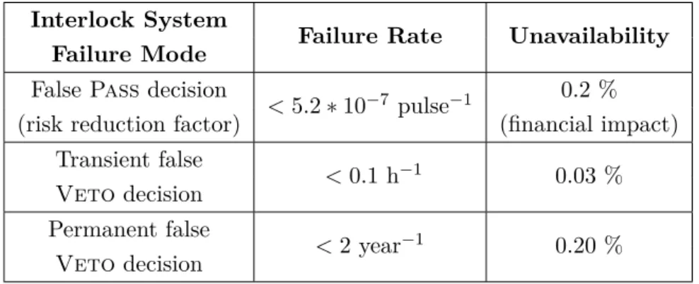
3.2 Failure modes requirements . . . 45
3.3 Interlock System Dependability Attribute . . . 46
3.4 Redundancy scenario . . . 48
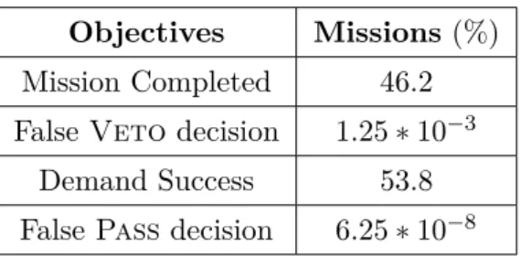
3.5 Simulation Objectives . . . 48
3.6 Simulation results - single node failure rates . . . 49
3.7 Set of critical interlock channels . . . 53
4.1 Interlock system functional behaviour . . . 58
4.2 Individual Data Analysis behaviour . . . 60
4.3 Next Cycle Permit behaviour . . . 60
5.1 CTF3 vacuum leak events . . . 78
5.2 Measurements results . . . 111
D.1 Annual CLIC radiation and fluence for electronic systems in the tunnel . 135 E.1 Simulation results - single node failure rates . . . 142
General Introduction
When entering in the particles accelerators field, the first thought that may arise is to realize the impressive complexity of these machines. Building these huge scientific tools requires the cooperation of many sectors : super-conductive magnets, Radio Frequency cavities, electronics (analog, numeric, microelectronic), cryogenic, vacuum, beam physics, mechanics, electric powering, etc. Building more and more powerful machines has created a need of protection and a new sector dedicated to the machine protection has been set up [10]. Indeed, the energy reached by the beam (360 MJ for the Large Hadron Collider (LHC)) and stocked in the equipment (10 GJ in LHC magnet system) are way more higher than the energy needed to melt on kilogram of copper (i.e. 700kJ) [11]. Consequently, particles accelerators can easily be damaged in case of uncontrolled energy release. The Interlock Systems are part of the machine protection. An Interlock System stops the machine when an unsafe condition occurs. The goal is to stop before the uncontrolled energy deposition.
The European Organisation for the Nuclear Research (CERN) is one of the larger par-ticles physics laboratory. Created in 1954, many machines have been built and part of them are still in operation. However, due to physics challenges evolution, new machines are studied. Among them, CERN has taken a leading part of the Compact Linear Colli-der (CLIC) [12] [13] [1] study and has started a close collaboration with the International Linear Collider (ILC) project. They both aim to explore new physics revealed by cur-rent accelerators and to test predicted theories : Higgs boson [14], dark matter [15], supersymmetrie [16], beyond the standard model [17], etc.
The CLIC design faces several challenges [18]. As it is a linear machine, the acceleration cavities are used only once and require a strong gradient. Thus, a novel two beams acceleration scheme has been introduced. Its feasibility demonstration is a crucial point for the project. Another critical feasibility study is the machine protection and the beam
operation. Part of it, the CLIC Interlock System study has been undertaken in the form of a thesis, presented in this manuscript.
In the CLIC machine protection framework, the Interlock System concepts have been defined [19]. It is based on a beam permit system [20] and a new post-pulse analysis, dedicated to linear colliders.
The thesis works attempt to answer the following question : how to design an Interlock
System for a linear collider ?
From the state of the art, some works have already been done on the Interlock System design. Indeed, a thesis has been performed on the LHC Interlock System to carry on the work from prototype to a fully tested and operational system [5]. Another example is the recent method to use Programmable Logic Device (PLD) in similar systems [21]. The presented thesis works undertake the design from concepts up to the prototype, thus complementing the two previously mentioned works.
To answer the main problematic, we propose to introduce an industrial methodology inspired by a system engineering standard, and to apply it to the CLIC Interlock System project. The goal is to be transparent on each method steps, thus allowing understanding, enhancement and correction of the design. The idea behind is to be able to use this method as a basis to develop future interlock systems. A special focus is proposed to be taken for the dependability, as it is a critical quality for an Interlock System.
Chapter 2 presents the context, starting from the physics particles challenges up to the CLIC machine protection. It expands on the problematic of the thesis and performs the state of the art on interlock and selected protection systems.
In chapter 3, the conditions of use and the system interfaces are defined. The central part is the establishment of the functional and performance requirements. It is done with an Institute of Electrical and Electronics Engineers (IEEE) standard as a guideline. A part of the chapter is dedicated to reliability and availability requirements determination. It proposes a methodology to verify if a design is compliant with these requirements. The last part explains in details the critical interfaces, extract the constraints, and how the expectations from the Interlock System to these interfaced systems are produced.
Chapter 4 presents the Interlock System design proposal. It explains the functional analysis done with the help of the IEEE standard. Finally, the implementation proposal, based on the functional analysis and concepts to implement, is presented. Going further, it proposes an implementation to the hardware modules level.
In chapter 5, the design verification is explained. The feasibility study performed in CLIC Test Facility 3 (CTF3) is presented : it is studying the post-pulse analysis application
in operational environment through a JAVA software. The hardware demonstration is described from the VHDL blocks up to the whole test bench. The measurements which aim to prove the design compliance are then examined.
Finally, the chapter 6 concludes the thesis works. It is proposing the short and long term improvements that would enhance these works.
Context and state of the art
2.1
Introduction
This thesis is focused on the design process of a dependable interlock system, applied to the CLIC. Before going into the design process, there are two needs : to explain the context and to define the starting point of the thesis works.
This chapter follows a top-bottom approach. The nowadays challenges in particle physics are introduced. The involvement in this field of the CERN, where the thesis has been done, is presented. Going more specific, the interest is focused on two proposed high energy linear colliders : the CLIC and the ILC. The next step is to give an overview of the CLIC machine protection strategy. It leads to introduce the CLIC Interlock System concepts. At that point, the problematic of the thesis is set up. The two last sections are dedicated to the background on protection systems related to interlock systems. The fifth section presents the interlock systems in a generic way, synthesizing the state of the art. The last section is more specific and presents five selected protection systems which are the main design references for these thesis works.
2.2
Particle Physics and CERN
In order to explain the thesis subject, it is needed to introduce the particles accelerators and therefore their purposes. It starts with the standard model.
2.2.1 Challenges in particle physics
The goal in physics is to understand the basic structures and laws, from infinite high scale (stars, galaxies clusters) to infinite low scale (fundamental particles) [22].
a. Building the standard model
The particle physics has started with the discoveries of different atoms. A great simpli-fication has been made when it has been realized that atoms can be unified with three particles : protons, neutrons and electrons.
In the beginning of the twentieth century, new particles from cosmic rays have been discovered. There was no system to classify them. They have been organized in regard with their properties : mass, charge, spin and lifetime (time before decay in lighter particles).
To simplify this organization, new particles, so-called quarks, have been predicted. Their combination can describe the other particles. This is the birth of the standard model.
The standard model comprises fundamental particles (6 quarks and 6 leptons) and fun-damental forces as represented in Figure 2.1, [17]. The forces are represented via force carriers :
– The weak force is seen through the bosons W and Z. It explains the energy production in the sun and the radioactivity.
– The electromagnetic force carrier is the photon. It is responsible for the transmission of light and magnet attraction force.
– The strong force is represented with gluons. It is responsible for nucleus cohesion.
To synthesize, the standard model is unifying the strong, weak and electromagnetic forces. It is very precise at both low and high energy. However, it remains incomplete : new particles and interaction are needed to cover some gaps.
b. Beyond the standard model
The standard model has several limitations [2], [17] :
– It does not explain how gravity is connected to the other fundamental forces. In other words, it does not comprise the Einstein’s general theory of relativity.
– It does not explain why the fundamental particles are the quarks and leptons (and their numbers).
c
charmu
upt
tops
stranged
dowmb
bottomν
e electron neutrinoν
µ muon neutrinoν
τ tau neutrinoe
electronµ
muonτ
tauγ
photonZ
Z bosonW
W bosong
gluon Higgs boson Qu ar ks Let p o n s Force carriersFigure 2.1: Standard model particles common representation
– It does not explain the existence of the dark matter and dark energy. – It does not explain the mass existence of neutrinos.
However, several models beyond the standard model have been predicted. One of them predicts a mechanism called Higgs field [14], which gives mass to fundamental particles. This hypothesis could contain particles with properties similar to dark matter. This Higgs field could be studied through its particle : the Higgs boson.
c. Challenges in particle physics
Hereunder are presented a selected bunch of nowadays challenges in particle physics :
Dark matter/energy The known matter (galaxies) is estimated to account only for 4% of the content of the universe. What remaining is dark matter and dark energy. Despite there are evidences of these phenomenons (gravitational clues), no theories have been proved until now. Some of them are related with particle physics such as the
supersymmetry theory [16] or the hidden valley theory [15].
Supersymmetry The supersymmetry is a theoretical expansion of the standard mo-del. It predicts a partner particle for each particle of the standard model : standard bosons would have supersymmetric fermions and the other way around. This theory
would resolve several gaps of the standard model (among them, the Higgs boson mass). It would unify the force strength at very high energy, making more understandable the state of the early universe. It would be a step closer to the grand unified theory.
Gravity and standard model Several tracks to include the gravity force to the standard model are followed. There is research for the hypothetical gravitons. Another point is to explain why the gravitation is so weak compared to the three other forces. Some hypothesis predict tiny black holes or extra dimensions that could appear during collisions. It could be a solution to this challenge.
Compositeness The compositeness is a theory predicting every particle of the stan-dard model are made up of smaller unit called preons.
There are many other challenges that have not been described (neutrino mass, muons physics, extra dimensions, grand unifications). These particle physics challenges are stu-died by many institutes and laboratories around the world : for instance the Fermi National Accelerator Laboratory (FNAL) in North America, the Shanghai Institute of Applied Physics (Sinap) in Asia, the European Synchrotron Radiation Facility (ESRF) and CERN in Europe. The thesis has been undertaken at CERN.
2.2.2 European Organisation for the Nuclear Research
The CERN is the world’s largest particle physicist laboratory. It is made up of 20 mem-ber states. More than 600 institutes and universities use CERN facilities. About 10000 scientists working in collaboration and 2400 are employed by CERN.
The CERN’s aims is the fundamental research in high energy physics. Its goal is to study fundamental structure of universe and state of the matter. The CERN intends to carry on the challenges previously mentioned.
The research tools used at CERN are particles accelerators. The principle is to accelerate particle beams (protons, leptons or ions) and make them collide together or with a fixed target. The resulting collisions are then studied by detectors.
In Figure 2.2 is represented the accelerator complex at CERN. It is a chain of small ac-celerators (like Linac 4) pre-accelerating and bunching the beam up to large acac-celerators like the Super Proton Synchrotron (SPS) or the more known LHC.
Figure 2.2: CERN accelerators complex
The beam collisions are studied by many experiments at different locations of the com-plex. In the LHC case, there are two multi-purposes detectors : ATLAS (A Toroidal LHC ApparatuS) and CMS (Compact Muon Solenoid). They both look for Higgs boson, extra dimensions and dark matter. In Figure 2.3 is represented the type of event registered with beam collisions.
Figure 2.3: CMS Higgs Search - collision electrons/muons at 8 TeV
There are also specialized detectors like ALICE (A Large Ion Collider Experiment), studying heavy ions for quark-gluon plasma understanding and LHCb (LHC beauty), studying matter/antimatter through the quark beauty.
Apart LHC, there are many other experiments that use beam collisions : for instance COMPASS (Common Muon and Proton Apparatus for Structure and Spectroscopy), which looks into hadrons structure to study spin property. We can cite CLOUD (Cosmics Leaving Outdoor Droplet), which studies link between cosmic rays and cloud formation.
To finish, the Antiproton Decelerator (AD) is used for many experiments to study anti-matter, from earth gravitational acceleration measurement to cancer therapy suitability.
CERN is not only about high energy physics. It is pushing the technology frontier for supporting the research. The main example is the world wide web created at CERN to share physics data over the world (first website : http ://info.cern.ch/).
2.3
High energy linear colliders overview
The high energy lepton linear colliders are the most desirable high energy facilities af-ter LHC era. The hadrons colliders such as the LHC are used at the energy frontier as discovery facilities. Conversely, leptons colliders are used for precision physics. Cur-rently, two linear colliders are proposed : the ILC and the CLIC. The ILC is based on superconducting technology in the TeV range (0.5 TeV) whereas the CLIC is designed on a new two beams acceleration approach in the multi-TeV (3 TeV) range. The choice of the built machine will be based on one hand on their technological maturity and on the other hand on the requirements from physics results. Therefore, a close and fruitful collaboration is established between ILC and CLIC.
The last lepton collider at CERN was the Large Electron-Positron collider (LEP). This circular collider was energy-limited by the synchrotron radiation effect. This parasite radiation is proportional to the invert of the cubic mass of the particles. Consequently, light particles such as electrons and positrons induce bigger radiation than hadrons. Linear accelerators consequently avoid the synchrotron radiation. The main disadvantage of a linear collider is that the accelerating cavities are used only once, implying a much longer complex than a circular collider for equivalent energy.
2.3.1 CLIC overview
The CLIC is an international project with collaborations with more than 30 institutes around the world. The project is currently in a research and development phase. The next step is to deliver a technical design report (projected for 2016). The main issue is to demonstrate the feasibility of this extensive project, whether in term of cost, time or
technological challenges. Therefore, a test facility named CTF3 has been built for the feasibility study.
The CLIC aims to provide particles collisions at a center-of-mass energy of 3 TeV. The luminosity will be reached with powerful beam (14 MW for the main beam) and collision with extremely small dimensions (emittance of 1 nm on vertical plane). Because the accelerating structures are used only once per pulse, they are required to have a high gradient of 100 MV/m. The CLIC project foresees to have only one interaction point (IP). At this area, a push-pull concept will allow to have two detectors in the same cavern, as similar to the ILC project (Figure 2.4).
Figure 2.4: CLIC detectors push-pull scheme [1]
a. CLIC scheme overview
In this paragraph, a short explanation of the CLIC layout (Figure 2.5) is given.
Main beam complex : The injection complex is the source of particles. It generates 2.4 GeV electrons and positrons. The positrons are generated by shooting some electrons into a hybrid target.
The damping ring aims to reduce drastically the beam emittance. It has to generate the smallest emittance than ever achieved, 500 nm horizontally and 5 nm vertically.
Figure 2.5: Schematic overview of the CLIC layout
The Ring To the Main Linac (RTML) aims to prepare the beam to the main linac injection. It is made up of a booster linac, which accelerates the beam at 9 GeV, a transfer line of 21 km, the turnaround, decreasing the emittance through synchrotron radiation and finally the bunch-compressor, delivering the beam to the main linac.
The main linac is a 21 km long accelerator where the main beam energy is increased from 9 GeV to 1.5 TeV. The beam delivery system aims to guide safely the 15 MW beam to the interaction point. At this point, a pair of detectors will be set. The post-collision beam will be then dumped by the beam dumping system.
Drive beam complex : The drive beam complex can be divided in three parts. The first part is where the electron trains are generated and then accelerated up to 2.38 GeV.
The second part is the compression stage. The beam will be compressed through a delay loop and two combiner rings, leading to the beam peak current of 100 A.
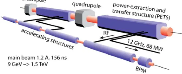
The third part is the decelerator stage. The drive beam is made up of 24 trains (after the combiner rings) and each one will go to one of the 24 deceleration areas (blue rectangles in Figure 2.5). At that point, the energy will be extracted from the drive beam to the main beam through several Power Extraction and Transfer Structure (PETS).
b. Feasibility Issue
Before validating the CLIC project, some critical points must be demonstrated as fea-sible. These feasibility issues [18] are listed hereafter.
The first challenge is the drive beam generation. This beam has to be generated with a 100 A stable intensity, with a 12 GHz bunch generation and a frequency multiplication factor of 24.
The second point is the drive beam Radio Frequency (RF) generation, more precisely, the PETS development. Its principle is to transmit RF power from a low-energy high-intensity beam (drive beam) to a low-high-intensity high-energy beam (main beam) which will be involved in collisions. This concept is represented in Figure 2.6.
Figure 2.6: Illustration of two beam accelerating scheme
The third challenge is the high gradient of accelerating structures (100 MV/m). This parameter must be reached with a RF efficiency of 27% and a breakdown rate lower than 3.10−7.m−1.
As said before, one of the CLIC novel approaches is the two beams acceleration scheme. This concept has to be demonstrated in compact module, including all technical sub-systems such as RF and vacuum. It has to send the RF energy from the drive beam to the main beam with a pulse length of 170 ns. This operation involves a high beam to beam stability (accuracy of 0.07 ps).
A fifth point is the ultra low beam emittance. This parameter is a mandatory condition for high luminosity. The CLIC system has to be able to generate ultra low emittance and to preserve it to reach the expected beam size at the interaction point.
Another challenge is the alignment and the stabilization system. The CLIC needs a 15 µm alignment accuracy, and a vertical displacement lower than 1.5 nm above 1 Hz vibrations.
At least but not the last, the feasibility of the machine operation and the machine protection has to be demonstrated.
c. CLIC operational scenario
The safe operation of the CLIC requires testing each system before starting physics experiments. Thence, an operational scenario has been proposed [19]. It allows to test gradually and safely each system of the two beams trajectory. A beam is considered safe when its energy is under the yield limit in copper (62 J/g).
Main Beam operational scenario The nominal main beam is above safe condition by 4 orders of magnitude. In order to ramp up safely the beam, the strategy is to reduce its luminosity. A first decrease can be done by reducing the number of bunches. A second cut is realizable by reducing the current per bunch. Finally, the last reduction comes from the beam size growing (emittance).
The operational scenario consists to send a safe beam. Then, the aim is to cancel pro-gressively the luminosity reduction explained above as long as the protection systems allow it, to finally reach the nominal main beam.
Drive Beam operational scenario The drive beam is above the safe condition by a factor of 100. A safe drive beam can be generated by reducing the charge density (less particles).
The operational scenario is to increase the charge density step by step as long as the protection systems allow it.
2.3.2 ILC overview
The ILC is a worldwide international collaboration of 300 institutes. Its global design effort, mandated by the International Committee for Future Accelerators (ICFA)), has led to deliver the reference design report in 2007. At that point, high risk challenges have been identified and the research and development on them has led to release the
The ILC is a electron-positron collider of 31 km length. It is based on 15000 SuperCon-ductive Radio Frequency (SCRF) cavities expected to deliver an accelerating gradient of 31.5 MV/m. The particles are accelerated with two linacs to have a collision energy of 0.5 TeV. It is foreseen to have a staged construction, thus starting the collision energy at 0.3 TeV and extensible up to 1 TeV. The collision events will be recorded with two detectors at the interaction region. The push-pull mode will be used.
a. Physics goals
The purpose of the ILC is to take up several physics challenges. First of it, the study of the Higgs boson and associated particles will start at 125 GeV, the collision energy where it must appear (Figure 2.7). The high precision measurements of the rates of the decay of the Higgs boson will be achieved because lepton colliders have less background events than hadron colliders. Moreover, this study will be completed at others energy (250 and 500 GeV) and by the determination of the Higgs boson self-interaction. One of the question of interest is to determine if the Higgs field is the only one to create mass or if there are additional particles which may contribute.
Figure 2.7: Simulation of a Higgs decay at ILC detector (courtesy to Norman Graf)
The second challenge that would be undertaken by the ILC is the study of the Supersym-metry. Regarding this theory, it is needed to have a matter-type Higgs particles. The ILC will search for them and measure their properties (quantum numbers and couplings).
A third major challenge to be noticed is the study of new interactions for pair production. It will be focused on W boson and top quark. Moreover the mass of the top quark will be precisely measured. Indeed, this quark is the heaviest fundamental particle in the standard model and may help to understand the Higgs field.
b. ILC scheme overview
In this paragraph, a short overview of the ILC layout (Figure 2.8) will be explained. From the particle sources Interaction Region, the ILC machine is divided in several parts.
Figure 2.8: Schematic overview of the ILC layout [2]
The electrons are generated with a laser/photocathode interaction in a DC gun. Some structures are then bunching and pre-accelerating the particles.
The positrons are generated with the electron beam. The accelerated beam is sent to undulators which generate photons. These photons are then sent to a titanium-alloy target, thus generating electron-positron pairs. A capture system extract the positrons which are then bunched and pre-accelerated.
The next machine parts for both types of particle are the damping rings. They aim to reduce the emittance. They must achieve a vertical emittance of 20 nm (five order of magnitude) and have to deal with beam compression and decompression (factor 90).
The two main linacs accelerate particles from 15 GeV to 250 GeV. It is done with 7400 SCRF cavities. Working at 1.3 GHz, they shall deliver an accelerating gradient of 31.5 MV/m with a spread of +/-20%, useful for physics events variation. The RF power comes from klystrons, each of them generating 10 MW. The klystrons repartition is balanced
between to schemes : either a distributed scheme all along the collider or a cluster scheme where klystrons would be gathered at strategic points. The choice mainly depends of the machine location ground topology. As shown in Figure 2.9, the cavities are gathered in a cryomodule to cool them down at 2 K.
Figure 2.9: Schematic the ILC cryomodule [2]
At the interaction region, the particles will collide. To perform the physics measure-ments, two detectors are foreseen : the Silicon Detector (SiD) and the International Large Detector (ILD), represented in Figure 2.10.
Figure 2.10: ILC Detectors - SiD (left) and ILD (right) [2]
Both detectors have a high resolution for events reconstruction through the newly deve-loped particle flow algorithm.
To maximize the detector efficiency, power pulsing have been implemented (switching-off part of equipment between particles trains). Thus, it reduces the heat load and the cooling system, resulting in less dead space.
These two detectors will be used at the same interaction region with a push-pull scheme. In order to optimize the ILC integrated luminosity, the swapping operation will take less
than 1 day. While one detector is probing physics events, the other one in is maintenance. The goal is to have two independent, complementary and competitive detectors to find new physics results.
They are based on a combination of tracking systems and electromagnetic and hadrons calorimetry in an intense magnetic field (5 T for SiD and 3.5 T for ILD). On one side, the SiD is designed as compact, thus enabling higher granularity of calorimeters detectors. On the other side, the ILD is larger to enable a better particle separation [23].
c. Main R & D effort
During the Technical Design Phase, the main research and development efforts have been focused on the SCRF cavities. The goal has been to achieve these cavities with a gradient of 35 MV/m in a reproducible way. The first step has been to study the limitations, among them, the field emission quench causing surface effect. The next step has been to establish a fabrication process to reach the required gradient and a production yield of 90%. As many institutes have been involved in this research effort, an extra challenge have been to ensure the plug compatibility (integration test) of the different cryomodule. In order to be ready for the mass production, several companies have been enabled to produce cavities compliant with ILC requirements through technology transfer.
2.3.3 CLIC and ILC parameters comparison
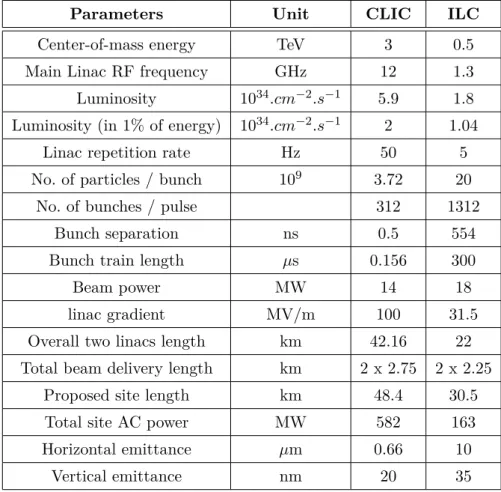
In Table 2.1 are listed the main parameters for ILC (500 GeV design) and CLIC (main beam). From interlock system point of view, there are several differences to note. First, the repetition rate has a difference one order of magnitude between the two machines. Performing inter-pulse analysis in ILC would be easier in term of response time constraint. A second difference is the site length which would act in a non-negligible way on the response time for the signal transmission.
2.4
CLIC Machine protection overview
On high energy accelerator projects such as the CLIC, the machine protection is a vital part. The mandate of the machine protection study is to protect various CLIC components from damage which could be caused by uncontrolled energy release (from beam and/or equipments). Its mission is to reduce risk to a tolerable level. A risk is tolerable when the sum of their financial impacts and operational downtime impacts are lower than a few percent of the whole budget and machine availability expectation.
Table 2.1: ILC and CLIC parameters comparison
Parameters Unit CLIC ILC
Center-of-mass energy TeV 3 0.5
Main Linac RF frequency GHz 12 1.3 Luminosity 1034.cm−2.s−1 5.9 1.8 Luminosity (in 1% of energy) 1034.cm−2.s−1 2 1.04
Linac repetition rate Hz 50 5
No. of particles / bunch 109 3.72 20
No. of bunches / pulse 312 1312
Bunch separation ns 0.5 554
Bunch train length µs 0.156 300
Beam power MW 14 18
linac gradient MV/m 100 31.5
Overall two linacs length km 42.16 22 Total beam delivery length km 2 x 2.75 2 x 2.25
Proposed site length km 48.4 30.5
Total site AC power MW 582 163
Horizontal emittance µm 0.66 10
Vertical emittance nm 20 35
Hereunder are described the failures types and the protection strategies planned. In a second part will be described summarily the machine protection systems.
2.4.1 Failures type and protection strategies
We could separate the CLIC failures in three categories :
Fast failures The time scale of these failures is the same than the beam flight in the accelerator complex. After a certain point, the beam cannot be stopped because of beam travelling at speed of light. The main fast failures come from RF breakdown or kicker misfiring which may send the beam out of its trajectory. Also, it could come from RF klystron trip which could disrupt the beam and involve large losses.
The machine protection strategy against fast failure is based on passive protection.
Inter-cycle failures These failures occur during the time between two pulses, i.e., 20 ms. This type of error could be caused by any sub-systems of the accelerator complex
affecting directly or indirectly the beam safety : for example, power supply, positioning system, vacuum pump.
The machine protection strategy against inter-cycle failure is based on two points : first, an Interlock System which would protect the machine during the first 18 ms. Secondly, a
safe by construction principle would be applied on sub-systems for the remaining 2 ms.
Slow failures These failures are slower than CLIC repetition rate (50 Hz). They could come from temperature or alignment drifts or from the beam feedback saturation (which is supposed to control drifts).
The machine protection strategy against slow failure is based on the post-pulse analysis.
2.4.2 Machine Protection Systems
The CLIC Machine Protection is revolved around 4 main systems described below. Each system is designed for a specific time scale.
Static protections The static protections are passive elements integrated such as collimators and spoilers. There are mostly associated with kickers and are located at extraction points (damping rings, combiner rings and turnaround). They have to be able to withstand the whole pulse.
Real time machine protection Some fast machine protection systems could be developed on a case basis. A real time system will be able to dump (at least partially) an unsafe beam in flight. This can be done through two principles. First, if the beam trajectory is not linear : An unsafe parameter (e.g. beam losses) will be detected and the beam will be stopped by taking a more direct path. The most obvious examples are the rings (damping and combiner rings) and the turnaround. Secondly, if the beam is not going at speed of light : An unsafe parameter will be detected and the beam source will be inhibited. The most obvious example is the drive beam linac.
Interlock System and post-pulse analysis It is the central topic of this thesis and are described longer in section 2.5
Safe by construction principle As the CLIC Interlock system cannot protect the
principle has been set to support this blind period. The safe by construction principle establishes that CLIC active equipment have to remain within their tolerance for 2 ms when they start to fail. A preliminary study gives an equipment inertia requirement of T > 20 ms. Thus, with this principle, the fault does not affect dangerously the beam in flight and will be caught by the Interlock System during the next inter-cycle (before next pulse).
2.5
CLIC Interlock system and thesis problematic
The CLIC Interlock System is based on two concepts : the beam permit and the post-pulse analysis. They are intended to protect a failure type : inter-cycle for beam permit and slow failures for both concepts .
2.5.1 Beam Permit
The beam permit concept is the backbone of the CLIC Interlock System. It is inspired by the LHC Beam Interlock System [5].
The beam permit has two states : a Pass decision is authorizing the next pulse operation and a Veto decision is inhibiting next pulses operation. This beam permit is a And-combination of the local interlock requests. The local interlock requests are received by local nodes (referred later as slave nodes), geographically distributed over the machine. The combination of these local interlock requests to the beam permit is assured by the beam permit loop.
This concept is intended to protect critical equipment failures between two pulses (inter-cycle) and may be used by the post-pulse analysis for slow failures.
This beam permit concept is represented in Figure 2.11 and is explained in deeper detail in the design proposal chapter (cf. a.).
2.5.2 Post-pulse analysis
In linear collider case, once the beam is in the pipe, it is impossible to stop it on a failure detection. Consequently the novel concept of post-pulse analysis has been introduced. The goal is to have a strong confidence for the next pulse stability. Thus, the post-pulse analysis aims to check the last pulse quality. In case of bad quality, the next pulse will be inhibited via the beam permit previously mentioned.
Master Slave Slave
Beam Permit
Local Interlock Local Interlock
Figure 2.11: Beam permit concept
This concept is intended to protect again slow failures with a time scale larger than the machine cycle period, such as alignment drift.
The main systems to be scrutinized on are the Beam Loss Monitors (BLMs) which are the line of last defence for detecting beam failures.
2.5.3 Thesis problematic definition
The thesis presents the design of a dependable interlock system for linear colliders.
Design A previous thesis named A Beam Interlock System for CERN High Energy
Accelerators [5] has been performed in 2006. It presents the work to design the LHC
Beam Interlock System, starting from the prototype systems and finishing with the operating interlock system.
My thesis works are complementary as it is explains the work from the concepts to prototype systems. Endorsing the IEEE 1220 system life cycle terminology (Figure 2.12), my thesis presents the work starting from system definition to the preliminary design.
Figure 2.12: Typical system life cycle [3]
Dependable The dependability is the main characteristic an interlock system must fulfil. A lots of studies have been performed to evaluate dependability properties of existing interlock systems [24], [25] but few of them at the design phase. The aim of the thesis is to establish them at the design phase, and give a generic methodology to do so.
Linar collider As described previously, the thesis has been performed as part of the CLIC project, with one concept applicable to linear colliders (post-pulse analysis).
2.6
Introduction to interlock systems
This section introduce interlock systems in the field of particle accelerator in a generic way.
The starting point is the need of machine protection : building more and more powerful machines has raised the hazard level because of possibility of uncontrolled energy re-lease, mainly from beam and equipment. Thus, interlock system have been introduced to prevent the damage resulting from these unwanted events.
The focus is done on interlock systems preventing beam hazard. Indeed, equipment interlocks (such as [26] or [27]) are case-specific and may have only the interlocking function as a common basis. In addition, interlock systems deals with machine safety and are usually decoupled with personal safety.
As part of machine protection, interlock systems share common goals. The next points describe the functions and the requirements that interlock systems may have in common, without machine specificity.
2.6.1 Protect the machine - Beam Interlock Function
To prevent the machine from beam damage, the interlock systems are using their main function : stopping beam operation (e.g. [20]) or reducing pulse frequency (e.g. [6]). To detect when the operation is unsafe (i.e., when to stop the beam), the systems get as input monitoring data on equipment that can affect the beam stability (such as power converter or magnets) and monitoring data on equipment probing the beam stability (such as beam position monitors or beam loss monitors).
The core function of interlock systems is to gather critical information and to synthesize them in a permit, affecting the beam operation.
This permit is then released to output devices (such as source gun or extraction/injec-tion/dumping kickers). These outputs will stop beam operation in consistence with the permit state.
The effect of this permit is fundamentally different between circular and linear colliders. For the latter, the permit is able to act only on the next pulse because the speed of
beam is close to the speed of light. In the ring machines, the beam permit will act on the circulating beam and/or the injection of new beams.
2.6.2 High dependability requirements
Failures of interlock systems can have two types of impact : machine damage and/or a decrease of machine availability. Consequently, the interlock systems have stringent dependability requirements, mainly in terms of reliability and availability. Hereunder are listed different ways used to reach these objectives :
Fail-safe design A fail-safe design ensures system failures to lead to safe failures : in interlock systems case, to stop the machine is safer than let it run without safe conditions or the protection system being blind ([11], p.26).
Redundancy One of the most powerful mechanism in order to have a high dependable system is the use of redundancy [28]. The point is to duplicate the system and add a well-designed voting system. Thus, a single element of redundant system has less stringent requirements and the system is more easily designable.
Test and Monitoring Failure rates are usually established considering an interlock system as good as new. To ensure this state, monitoring is required.
Two types of monitoring can be distinguished : on one side, live monitoring ensures proper condition of the system while operating and shows up warning for the next technical stop (e.g. a redundant power supply failure). On the other side, monitoring while not operating can allow more advanced tests and therefore check all functions, especially the barely used. It implies to implement the concept of testability in the early step of the design phase. Finally, knowledge about Mean Time Between Failures (MTBF) of single components allows preventive maintenance.
Flexibility To ensure high availability, interlock systems need to be configurable to improve its flexibility. Indeed, special cases (such as test mode, safe beam mode or special accelerator structure configuration) may require an interlock system to behave differently than initially foreseen (e.g. masking inputs).
2.6.3 Common design
Based on several interlock systems [20], [6], [29], [30], it is possible to describe a generic interlock system :
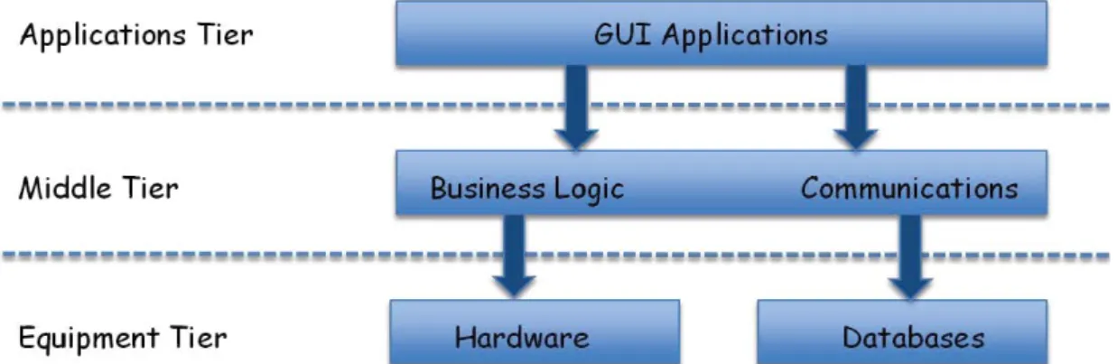
In a general way, an interlock system is a distributed hardware system. It may be based on Field Programmable Gate Array (FPGA) or Programmable Logic Controller (PLC). The most common architecture is a tree layout but can also be implemented with a circular and/or daisy-chained layout. It usually has a master unit delivering the final beam permit. The data transmission between different modules (e.g., between slave and master modules) requires high speed capacity, noise and radiation immunity. These communication links are often implemented with optical fibres.
Although interlock systems are specific to the machine they are protecting, they usually share the same subsystems. The figure 2.13 gives an systemic overview of a generic interlock system. these subsystems are hereunder described :
Figure 2.13: Generic Interlock System overview [4]
Control system : It is responsible for configuration, update and is usually managed by expert only. It also implements the test and monitoring part.
Timing system : Interlock systems must work in synergy with other machine subsys-tems and the beam timing. Beam timing is especially crucial for linear colliders. In a less critical way, it is also used to time stamp the data for monitoring purpose.
Post-mortem : In addition to the interlock function, the interlock systems must pro-vide or help to propro-vide epro-vidence when an interlock occurs. It can be done either integrating a post-mortem’s like system [31] or providing information (such as time-stamped interlock request data) to this type of analysis system.
Interfaced devices : Interlock systems are interfaced with other systems. A crucial point is the question of the responsibility at the interface. A poor performance from interfaced systems will decrease the interlock function quality. To keep a high dependability level, the boundaries of the interlock systems must be clearly defined. In addition, expectations from interlock systems to interfaced systems, in term of dependability requirements, must be provided.
2.7
Selected protection systems
In this part, the goal is to give an overview of the current level of development in the interlock system field. The selected examples are either interlock systems or protection mechanisms which are strongly linked with CLIC Interlock System. The LHC Beam Interlock System constitutes the main reference work of this thesis.
2.7.1 LHC Beam Interlock System
The LHC is a machine running at high energy, with beam energy higher than 360MJ. It therefore generates beam hazard. Thus, there is a need of protection again uncontrolled beam losses. A Beam Interlock System (BIS) has been designed to prevent part of beam failures [20].
The principle of LHC BIS is to stop beam operation as soon as an unsafe beam state is detected. Beam operation is stopped by extracting the circulating beam (via the dumping beam system) and by inhibiting the beam injection. The beam state detection is based on failures of critical systems and high beam losses detection.
The response time is a stringent requirement and is conditioned by the type of failure and the accelerator architecture. As illustrated in Figure 2.14, the BIS has to transmit information from users interfaces anywhere in the LHC until the beam dumping system within 100 µs.
The dependability is one of the higher requirement. The LHC BIS has been specified to reach Safety Integrity Level (SIL) level 3. This can be translated into a mean time between unsafe failures between 100 and 1000 years.
t0 >80 us t1 20-120 us t2 <90 us t3 90 us t4 Fault / Dangerous Situation Occurs Beam Interlock System informed of fault condition Beam Dumping System informed of fault condition Beam Abort begins, aligned
with abort gap Beam abort completed
User System Process Beam Interlock System Process Beam Dumping System Process
DETECT COMMUNICATE SYNCHRONISE ABORT
Figure 2.14: LHC BIS response time requirement [5]
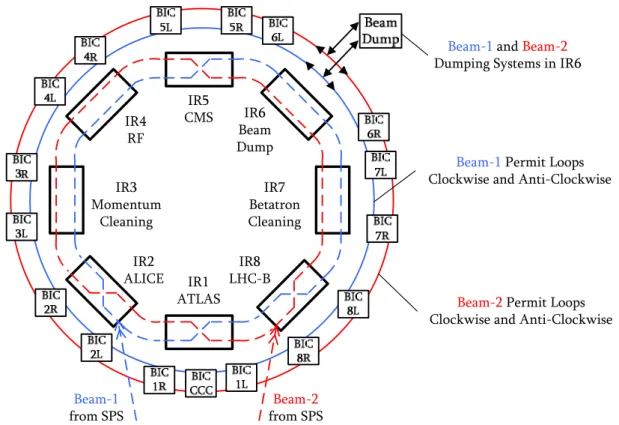
To cover the full LHC, the LHC BIS uses 140 interfaces with critical equipment. These interfaces are connected to 16 nodes. The actuator used to extract the beam from the LHC is the beam dumping system. The actuators used to inhibit beam injections are the injection kickers. The LHC BIS uses a redundant beam permit loop : it is a 10 MHz square wave signal transmitted clockwise and anticlockwise through optic fibres. Each node can open the loops. The lack of this loop signal leads to interlock. The LHC BIS architecture is represented on Figure 2.15.
IR5 CMS IR6 Beam Dump IR7 Betatron Cleaning IR8 LHC-B IR1 ATLAS IR2 ALICE IR3 Momentum Cleaning IR4 RF Beam-1 from SPS Beam-2 from SPS
Beam-1Permit Loops Clockwise and Anti-Clockwise
Beam-2Permit Loops Clockwise and Anti-Clockwise
Beam-1and Beam-2
Dumping Systems in IR6
Figure 2.15: LHC BIS architecture
The nodes are the main components of the BIS. Their core function is to perform an And operation of the user permit inputs and allow (or not) propagation of the beam permit loop signal. It is performed by the critical manager board. The other part of the
node is dedicated to live-monitoring and testing. It is performed by a different hardware board, keeping the critical and non-critical part separated. In order to provide evidence, a history buffer is implemented, allowing analysing events before an interlock trigger. A synoptic view of the node is showed on Figure 2.16.
Figure 2.16: LHC BIS Node synoptic view
2.7.2 Linac Coherent Light Source Interlock System
The Linac Coherent Light Source (LCLS) is a 2.5 km long linear accelerator, generating highly bright X-rays pulses to probe at the atomic scale.
An interlock system has been designed for the LCLS [6]. It is the main part of its machine protection. It shuts off the beam or reduces its repetition rate regarding the failure severity. To do so, the inputs are signals from beam loss and beam position monitors, among others. At the end, it has about one hundred of interlock request inputs. Concerning the outputs, it has direct access to mitigation devices (such as pulsed kicker magnet or mechanical shutter) to change the machine operation.
There is to note it processes fault data every 2.78 ms, while beam operation is 120 Hz. It accepts both digital and analogue inputs. An interesting fact is the threshold comparison performed on analogue value (to translate them into failures detection).
The interlock system is organized as a tree topology, as shown on figure 2.17. The slave nodes (a.k.a. link nodes) are able to have different configurations, thus adding flexibility to the whole system.
Figure 2.17: LCLS Interlock System Architecture [6]
The last point is about the technology : it is a FPGA based system. The critical links between master and slave nodes are made with dedicated gigabit ethernet.
2.7.3 Linac 4 watchdog
the Linac 4 is a 160 MeV linear accelerator starting the injection complex of the LHC (cf. Figure 2.2). One of its protection strategy is to use an interlock system. It is based on the same hardware as for the LHC but differently configured. As the LHC Interlock System has been already described, this part is focused on one protection mechanism, the watchdog, which is used as an input of the interlock system. The interesting part is the threshold comparison and the post-pulse losses evaluation.
The principle of the Linac 4 watchdog [32] is to compare beam transmission (in num-ber of charges) at different point of the Linac through beam current transformers. An illustration of this implementation is showed on figure 2.18
Source RF
Quadrupole Drift Tube Linac
Cell-Coupled Drift Tube Linac
Pi-Mode Structure
WatchDog
Figure 2.18: Linac 4 Watchdog implementation example
These comparisons will permit to detect excessive losses. Each comparison will be an input of the Linac 4 BIS, which will trigger an interlock as soon as one of its input fall down to False state and thus shut off the Linac beam.
For the Linac 4 watchdog, each comparison result (True or False) is configurable by the user following these points :
1. The definition of good pulse is defined through a threshold (above is good, below is bad pulse).
2. A bad-pulse counter is set at its maximum value (maximum value is defined by the user).
On each good pulse, the bad-pulse counter is incremented until its maximum value. On each bad pulse, this counter is decreased. Whenever the counter reaches zero, the watchdog will trigger the comparison result from True to False, leading to an interlock (through BIS). After a True to False transition, the watchdog has to be reset manually (latching mechanism) to restart Linac 4 beam operation.
The technology choice is a hardware FPGA-based solution with an acquisition chain to collect beam current transformer signals. The main reasons of this choice are the relia-bility and the reaction time offered by this technology. A pure software based watchdog solution would have led to higher operational flexibility. To reach an equivalent flexibility level, the designed system is implementing a software based superstructure in synergy with the hardware structure.
2.7.4 Real-time and post-pulse beam quality assessment for LHC beams
A novel concept for the CLIC Interlock System is the post-pulse analysis, strongly linked to beam quality. Beam quality analysis is also performed for LHC beams. Two solutions have been designed : the beam quality monitor in the SPS [33] and the injection quality
a. Beam quality definition
In this framework, beam quality is defined in terms of : - Small emittance
- Uniform bunch intensities (< +/- 10 %)
- Equal beam intensities for both beam (clockwise and anticlockwise beams) - Low tail population
- Satellite population reasonable - Low losses
b. Beam quality monitor at the SPS
This is the real time beam quality check. It checks the longitudinal quality of beam in the SPS. It is based on wall current monitor beam time-profile. The system dumps the beam in case of bad quality. The analysis speed is 10 ms of data acquisition and 10 ms of data analysis. The last check is performed 20 ms before the SPS extraction (i.e. LHC injection).
c. injection quality check at the LHC
This is the post-pulse (or post-injection) beam quality check. It inhibits the next injec-tion in case of bad injecinjec-tion. It is based on many beam observainjec-tion systems (beam loss monitors, beam position monitors, injection kickers, RF phase error). It is a Java appli-cation using both post-mortem and monitoring framework. The analysis takes up to 8 s. It is mainly used in synergy with the injection sequencer. The injection sequencer is a pre-programmed succession of different injection shots. It goes on next injection request only if the injection quality has been asserted.
2.7.5 Safe Machine Parameters
In high power accelerators, transferring machine parameters is needed for operation. However, some of them are safety relevant : Indeed, a corrupted transmitted parameter (such as safe beam flag) may lead to machine damage. In this purpose, in the LHC framework, the Safe Machine Parameters (SMP) has been developed [7].
The SMP is part of the machine protection and a special focus has been performed on its reliability and availability attributes. Its principle is to generate machine parameters based on a threshold comparison. A schematic overview is given on Figure 2.19.
Figure 2.19: Safe Machine Parameter Overview [7]
To compute the parameters, the SMP takes as inputs several values, mainly beam rela-ted : fast and slow beam current transformer, beam energy meter, beam position meters, beam energy tracking system, sequencer and software interlock system.
The parameters computed (listed on Figure 2.19) are then sent in different ways, regar-ding their criticality to users. The SMP users are listed hereunder :
- Extraction interlocks - RF modules
- Beam dumping system - BIS
- Injection kickers - Beam loss monitor - Collimation - Experiments
An interesting fact to notice is the fail-safe mechanism. When the inputs are not received, the SMP replaces them by the worst case values, generating thus worst case parameters.
The SMP is a distributed hardware system, based on FPGA. To reach dependability requirements, the critical path has been kept as simple as possible and separated from the monitoring (and more complex) part.
2.8
Conclusion
This chapter is mainly a presentation and synthesis work. It has briefly explained the scientific context (particle physics, CERN, linear colliders, ILC, CLIC machine protec-tion) of the thesis and introduced its problematic (CLIC Interlock System).
The state of the art relative to the subject has been described. With this chapter all the concepts (interlock systems, beam permit loop, post-pulse analysis) have been presented. Next chapters will cover the work carried during the thesis.
![Figure 2.19: Safe Machine Parameter Overview [7]](https://thumb-eu.123doks.com/thumbv2/123doknet/3536335.103548/43.892.176.777.132.548/figure-safe-machine-parameter-overview.webp)
![Table 3.3: Interlock System Dependability Attribute Attribute Definition [40] Value Availability readiness for](https://thumb-eu.123doks.com/thumbv2/123doknet/3536335.103548/56.892.254.692.149.400/table-interlock-dependability-attribute-attribute-definition-availability-readiness.webp)
![Figure 3.11: Damping rings dump system [9]](https://thumb-eu.123doks.com/thumbv2/123doknet/3536335.103548/64.892.158.788.472.616/figure-damping-rings-dump-system.webp)