O
pen
A
rchive
T
OULOUSE
A
rchive
O
uverte (
OATAO
)
OATAO is an open access repository that collects the work of Toulouse researchers and
makes it freely available over the web where possible.
This is an author-deposited version published in :
http://oatao.univ-toulouse.fr/
Eprints ID : 10972
To link to this article : DOI: 10.1049/iet-epa.2010.0180
http://dx.doi.org/10.1049/iet-epa.2010.0180
To cite this version
Bidart, Damien and Pietrzak-David, Maria and
Maussion, Pascal and Fadel, Maurice Mono inverter multi-parallel
permanent magnet synchronous motor:structure and control
strategy. (2011) IET Electric Power Applications, vol. 5 (n° 3). pp.
288-294. ISSN 1751-8660
Any correspondance concerning this service should be sent to the repository
administrator:
[email protected]
Mono inverter Multi parallel PMSM - Structure and
Control strategy
Damien Bidarta , Maria Pietrzak-Davidb , Pascal Maussionc , Maurice FadeldUniversit´e de Toulouse; LAPLACE; CNRS, INPT, UPS ; 2 rue Camichel, 31071 Toulouse Cedex France a [email protected] b [email protected] c [email protected] d [email protected] Abstract
This paper presents a new and original Mono inverter Multi parallel Permanent Magnet Synchronous Motor (PMSM) system. To obtain the stability of such a system, each of the motor synchronisms should always be respected regardless of their load torque. In this case, only one motor, called ”master motor”, will be self-piloted. If the chosen master motor is the one with the highest applied load torque, synchronism is respected for each of the motors. To find this machine, a solution which compares the rotor positions is thus developed. Experimental results are given for a system with 2 PMSM plugged in parallel. The proposed solution can however be applied to systems whatever the motor numbers, therefore additional simulations are provided for a 4 PMSM system.
1. Introduction
Due to the development of electromechanical actuators, Multi-Machine Sys-tems (MMS) are increasingly used in certain domains such as railway propulsion or textile [1][2] and research into such drive systems is of interest to the aeronau-tical industry (flaps and spoiler actuators, braking system...). However, a MMS with machines operating independently needs a high number of power switches. Consequently, these systems are heavy, bulky and quite expensive. To reduce
these disadvantages, it is therefore interesting to reduce the number of inverter-legs. Many studies have been carried out concerning the multi induction motors functioning with a single inverter [3]-[7] With such systems, flexibility and safe operation are increased and the field of the power applications can be extended. Among the electrical actuators, PMSM have the advantages of being brush-less, more robust and more easily produced than DC motors. Moreover they have a better power/weight ratio. Extensive literature concerning PMSM and their control is avaible [8]-[10].
However, the majority of systems with Multi-PMSM requires one inverter per PMSM, a system with n three-phase-PMSM needs thus 3n inverter-legs.
The main idea of this paper is to develop a controller for a single inverter multi parallel PMSM system. A certain number of works already exist [11]-[13].Those works being either with specified inverter structure, with specified control or applied to only two PMSM, they do not necessarily reduce each of the MMS disadvantages. The solution proposed in this study, already presented in a patent [14], uses a current controlled voltage source inverter and the master-slave configuration. This structure which use classical controllers [15] can easily be applied to systems regardless the motor number and can be used as a safety system in case of a fault of an inverter leg in a classical system.
With certain constraints (e.g. the motors have the same characteristics), only three inverter-legs are thus necessary whatever the number of PMSM. Admittedly, in such a system, each of the switches has to be oversized to admit a current value of n ∗ In instead of In but globally this system is better because
only 3 drivers are used instead of 3n, only 1 cooling system instead of n... In the second part of this paper, the proposed structure is described for a system with n PMSM plugged in parallel and generalities concerning the PMSM simulation and its stability are reminded. The third part describes the control strategy and experimentation results with 2 PMSM are provided. Those experimental results are presented for the first time and are convincing. The fourth part presents other studies done with this structure such as the influence of the initial position. Simulation with 4 PMSM plugged in parallel, which fulfill
the theory is presented.
2. The studied structure 2.1. Model of a single PMSM
All the machines being studied are smooth-air-gap PMSM and are supposed to have the same characteristics. The rotor field, created by permanent magnets, is constant. Due to the high inertia effect, the torque variations effects due to some distortions in the e.m.f are filtered. The e.m.f is therefore considered as sinusoidal.
The principal variables needed for the simulation of these machines are the angular position of the rotor θ, the stator currents is1,s2,s3 and the voltages
vs1,s2,s3[16]. The motor nominal values are listed in the appendix.
The electric equation for the phase number j is written as follows: vsj = R.isj+ L.
disj
dt + esj (1)
Where R is the stator resistance per phase, L the cyclic inductance and esj the electromagnetic force, which is assumed as sinusoidal and given by the
following equation:
esj= p.Ω.φM.sin(p.θ − (j − 1)
2π
3 ) (2)
with p the number of pole pairs and φM the maximal inductive flux.
Moreover the mechanical mode is defined by the equations (3) and (4) as below
Ω = dθ
dt (3)
J.dΩ
dt = Tem− TL− f0.Ω (4)
with f0the viscous coefficient, J the total inertia (N m.rad− 1
.s2
), Ω the rotor rotation speed (rad.s−1) and θ the rotor position (rad). TL represents the load
torque and Tem the electromagnetic torque (Nm). This torque is the additional
Tem = p.φM 3 X j=1 sin(p.θ − (j − 1)2π 3 ).isj (5)
2.2. The parallel structure
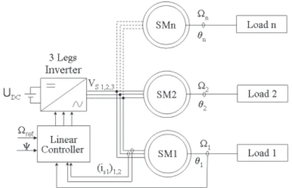
In the majority of MMS, each motor is supplied by its own inverter. To optimize the volume and the weight of those systems, the number of power electronic switches can be reduced. If the motors have the same characteristics and need to be controlled with the same rotation speed, they can indeed be plugged in parallel into a single inverter. As shown in Fig. 1, only one motor called ”master motor” is self-piloted. The other (SM2,...,SMn) are called ”slave-motors”. The same voltage (frequency and modulus) is applied to each of the motors so during the steady state, their rotation speed is the same.
In the case being studied, a current source PWM inverter [17] is chosen to supply the machines. Moreover, the master motor rotation speed is controlled using cartesian form (the three phase currents are independently controlled) [18][19]. To control PMSM, The used controllers are antiwindup PI (PIaw) [20] for the current and IP (proportional integral without zero [21]) for the rotation speed.
2.3. Stability study
Due to its low value, the stator resistance R will not be taken into account in this first study and during the steady state, the currents are considered as sinusoidal. This leads to the vector diagram for the machine represented in Fig. 2.
In this figure, ω = p.Ω is the electric pulsation and E, I and V respectively represent the RMS values of esi, isi and vsi. Moreover, three angles appear:
Ψ = (I; E), ϕ = (V; I) and δ = (V; E)
The electromagnetic torque value Tem can thus be calculated as follows [22]:
Tem= K1.I. cos(Ψ) = K2.Vω. sin(δ)
With K1= 3p.φM And K2= 3p.φML
The PMSM is distinguished by its rotor moving at the same rate as the oscillating field which drives it. This synchronism has to be always respected whatever the load torque and this condition is respected by self-piloting the ma-chine. With the structure described in Fig. 1, the slave machine(s) synchronism is guaranteed. As described in (6), the evolution of Tem(δ) is sinusoidal, thus the
motor stability depends on the δ value. When the load torque TL is suddenly
changed, the rotor rotation speed does not immediately change contrary to the δ electric angle. Consequently, the increase of TL leads to the increase of the
δ angle. When δ < π
2, this leads to the increase of the electromagnetic torque
which becomes stable again with the load torque. However, when δ > π 2, the
increase of TL leads to a decrease of Tem and the stability is not guaranteed.
Consequently, to be sure that the system stability is respected, the condition δ < π
2 has to be respected for each of the PMSM.
Concerning the notation, the index ”m” represents the master machine SMm
and the index ”i” represents one of the slave motors SMi.
When a load torque is applied to the master motor, the stability of this machine leads to the steady state: (Tem)m= (TL)mand the mechanical rotation
speed has the value Ωm. Due to the motor synchronism, the voltage angular
velocity is ωe = pΩm. The machines are plugged in parallel, so this voltage
angular velocity is the same for each of the motors. To respect the stability of SMi, its rotation speed during the steady state should be Ωi= ωep = Ωm, while
its applied load has the value (TL)i. Consequently, the electromagnetic torque
tends toward this value: (Tem)i = (TL)i. This torque value change leads thus
to the change of the δi angle. As described above, the stability of this system
is guaranteed as long as for each of the slave motors, δi<π2.
The master machine has so to be chosen between all the PMSM to insure the system stability. This choice depends on the load torque applied to each of the motors.
If (TL)m≥ (TL)i, δi ≤ δm, so δi < π/2,
=⇒ the slave motor i is stable.
=⇒ the stability of the slave motor i is not certified. 2.4. Used variables for choosing the master motor
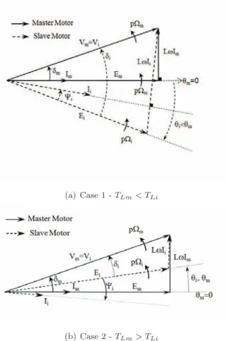
To obtain the maximum torque, Ψm= 0 is imposed (6), hence the master
motor torque is proportional to the applied current: (Tem)m = K1.Im. Fig. 3
plots the vector diagrams for the system motors described in Fig. 1. Two cases are represented: (TL)m< (TL)i in Fig. 3(a) and (TL)m> (TL)i in Fig. 3(b).
In this figure, it can be seen that the inequalities with the δ angles are verified as described above:
If (TL)m< (TL)i: δm< δi
If (TL)m> (TL)i: δm> δi
Consequently, the motor to which the highest load torque is applied has to be the master. The load torque values can however change so each of the motor can become master at any time.
It has been previously demonstrated that the motor with the highest load torque has also the highest δ = (V; E) angle. V is the same for all the motors therefore to compare the δ angles corresponds to comparing the e.m.f E position. Those e.m.f are linked to the magnet positions, which means that the rotor positions θmeca can be used to compare the δ angles. The electrical value of
this angle named θ = p.θmeca is particularly chosen. The angle δ + θ is the
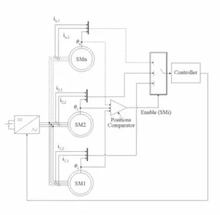
same for all of the motor so the machine which has the highest δ angle has the lowest θ position. Moreover, as the θ rotor positions are already used for the self-piloting so no complementary sensor is needed. To decide which motor is the master type, all of the rotor positions are thus compared to create a signal called ”Enable(SMi)”. One of the PMSM controller is chosen, depending on the value of this signal. This system is described in Fig. 4.
3. Experimentation with 2 PMSM 3.1. Creation of the Enable signal
If two PMSM are plugged in parallel, both θk positions are systematically
compared, creating the Enable signal (k=1 or 2 representing the PMSM1 or PMSM2). Those values can be quite similar so ∆θ = θ2− θ1≈ 0. In this case,
it is not necessary to take into account the load torque variations it they are too slight. The enable signal should indeed constantly change, which could create some oscillations on the speed signal during the steady state. To avoid this, an hysteresis is added after the comparator, the hysteresis value being chosen to obtain a compromise between the chosen ∆θ value for the Enable signal change and the redundancy of this signal change [15]. In the studied case, a value of H = π
100 is chosen. This compromise is not fixed and other values can be chosen
depending on the inertia of the motors and on the torques applied to them. However, with such a value, an electrical angular velocity ωe= 200rad.s−
1
and a sampling time rate of T = 8.10−4s, at least 100 samples are executed with
the same master motor before a possible change of the Enable signal.
After running for several hours, the θi absolute rotor positions can tend to
infinite. The positions chosen to compare the θi angle is then the modulo 2π
position. A logic combination which allows to compare the two positions 2π-modulated is integrated in the system, this position comparator is illustrated in Fig.5.
Additionally, a classical speed regulation is implemented for the chosen mas-ter motor and the stability of the system is respected.
3.2. Experimentation process
The experimental test bench, shown in Fig.6 includes a system with 2 PMSM (PMSM1 and PMSM2) plugged in parallel to the same inverter. Each of the motors is coupled to its own linear actuator ball screw driven (axis1 and axis2) and drives its own slide (slide1 and slide2). A third machine (Load motor) produces a controlled torque TLd and drives a third slide. This slide is rigidly
connected to the slide1, so that the torque variation −TLdis applied to PMSM1.
In this system, other load torques applied to the motors are due to the axis frictions (static, Coulomb, viscous and Stribeck friction). Simplified load torque equations are given in (7).
TL1= T01+ f1.Ω1− TLd
TL2= T02+ f2.Ω2
(7) During the steady state, with Ω = Ωref = 20rad.s−
1
, the axis frictions measured on the test bench are:
T01+ f1.Ω1≃ 0.4N m
T02+ f2.Ω2≃ 0.25N m
(8)
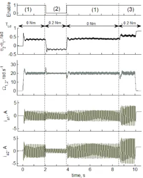
Three cases have to be tested during 4 phases: (1) TLd= 0 Nm =⇒ TL1≃ 0.4 > TL2≃ 0.25
(2) TLd= 0.2 Nm =⇒ TL1≃ 0.2 < TL2≃ 0.25
(3) TLd=-0.2 Nm =⇒ TL1≃ 0.6 > TL2≃ 0.25
According to the chosen control strategy, the machines should thus be con-trolled in this order: PMSM1 (1), PMSM2 (2) and PMSM1 (1 and (3)). 3.3. Experimental results
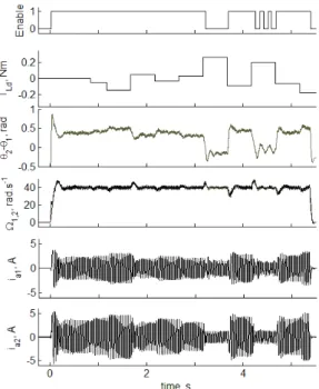
Fig. 7 represents the rotation speed and the current variation for both motors and the ∆θ position.
As it can be seen on this figure, the sign of ∆θ corresponds to the theory. Moreover, the master motor is the motor with the highest load torque. During the steady state, both of the motors have the same velocity and so the stability of the system is perfectly respected. During the transition, some peaks concerning the rotation speed appear (25%Ωref), this is due to the chosen control (IP scalar
controller). Moreover, it can be seen that a current (i.e a torque) regulation is obtained with only the master machine. Concerning the slave motor, the ψ angle value is 6= 0, consequently its efficiency is less than the master one. Thus, in spite of the fact that the torque produced by MS2 is the same during the different phases (T2≈ 0.25N m), the current values are not similar. When MS2
is the master motor (phase (2)), its rms value is I2≈ 0.64A whereas when it is
slave, its value is higher (2.6A(phase 1) and 3.5A (phase 3). The slave current values stay however acceptable for both of the motors.
In fig. 8, experimental results with a faster variation of the load torque Tld
are presented. Whatever the load transition, the stability of the system is still respected.
4. Other studies carried out with this structure 4.1. Influence of the electric angle initial value
During the start up of the motors, the values of the initial electric angles (θi)0
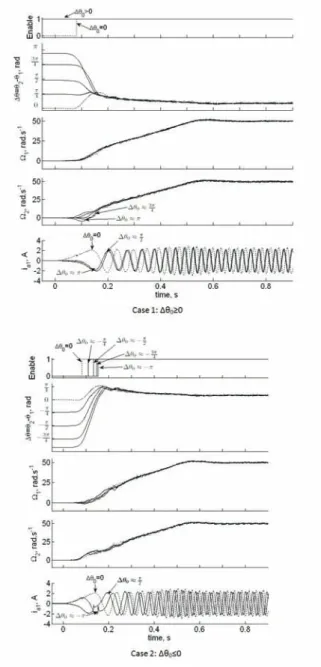
can be different for the machines. In this case, during the starting, the master motor is the one with the lowest θ value, this value being modulated between −π and π. Results shown in Fig. 9 represent the start up for different initial values of the ∆θ = θ2− θ1 angle. The experimental process is the same as the
one described above. As illustrated in this figure, the rotation speed reference is a slope and during the steady state: Ωref = 50rad.s−
1
. No load torque is added to PMSM1: TLd = 0N m, therefore during the experiment, PMSM1 has
the highest load torque and normally, this machine should be considered as the master motor.
The motor considered as the master one has the lower θ0value. As depicted
in Fig. 9, it can be seen that the difference angle ∆θ tends to the same value (∆θst) whatever the initial electric angle. This value corresponds to the δ angle
difference value during the steady state, the synchronism is therefore perfectly respected regardless the ∆θ0 value.
However it can be seen that the behavior of the slave motor depends on its θ0 value. During the start up, this value is indeed linked to the difference angle
between the rotor and the stator flux of the machines i.e of the δ angle described above.
However it can be seen that the behavior of the slave motor depends on its θ0 value. During the start up, this value is indeed linked to the difference
angle between the rotor and the stator flux of the machines i.e of the δ angle described above. Consequently, regarding the flux, if |∆θ0| < π2, the stator and
the rotor field of the slave motor are synchronous. The stability of the system is respected and as described above, θslavetends to θmaster. When —∆θ0| > π2,
|δslave| > π2 and the rotor field is attracted by the stator field. The rotation
speed of the slave motor is thus Ω < 0. Due to this, the value of |δ| is decreasing while δ < π
2. Due to the low rotation speed (it is the starting), the synchronism
of the motor can then be respected i.e the rotation speed becomes positive and the case described above is respected.
Two different cases are presented in Fig.9. If initially, ∆θ0 > 0, the master
motor is the one with the higher load torque value, so Enable signal is not chang-ing. However, if ∆θ0≤ 0, an enable signal change appears during the transient
state. Regarding the currents (i.e the produced torque), a peak appears during this change.
4.2. Simulations with 4 PMSM
In order to further validate the performance of the proposed control technic, a four motor drives was simulated using the Saber software.
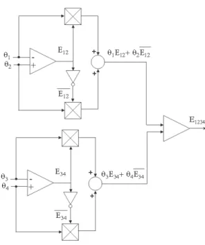
The motor with the lowest rotor position has the highest load torque and has to be controlled. As depicted in Fig. 10, a system with only three compara-tor is used. The rocompara-tor positions of the mocompara-tor 1 and 2 on the one hand and 3 and 4 on the other hand are compared. The comparisons are the same as those shown in Fig. 5 and they respectively create the digital signals E12and E34. By
comparing the signals (θ1.E12+ θ2.E12) and (θ3.E34+ θ4.E34), the lowest rotor
position is found. As shown in Fig. 10, this comparison gives a signal called E1234 which creates the control signals as follow:
Enable(SM1)= E12.E1234 Enable(SM3)= E34.E1234
Enable(SM2)= E12.E1234 Enable(SM4)= E34.E1234
rotation speed Ω. According to (9), the load equation is now added in the PMSM models
TL= (a + b.c(t)).Ω (9)
Concerning the simulation, the values of a, b and c are chosen for each of the machines so that during the steady states, the ratios load torques/nominal torque have the values written in Table 1:
t(s) 0 0.25 0.5 0.75 1 1.25 1.5 1.75 TL1 Tn 1 1 1 1 1 1 1 TL2 Tn 0.85 0.85 0.85 0.85 1.15 1.15 0.85 TL3 Tn 0.79 0.79 1.15 0.79 0.79 0.79 0.79 TL4 Tn 0.93 1.07 1.07 1.07 1.07 0.93 0.93
Table 1: Load torque variations
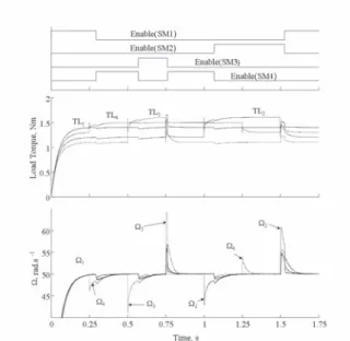
The time variations of those values are chosen to simulate a high number of master-slave switching situations in more realistic conditions. The variation of the rotation speed for each machine versus the time is represented in Fig. 11.
In this figure, it can be seen that the stability of the system is respected. Whatever the load torques on the four machines, the motor with the highest load torque during the transient state is indeed the master. The speed variation observed during the transitions have the same kind of shape as the transitions observed with two PMSM. Moreover, it can be noticed that certain transition peaks have a high value. For instance, (Ω3)max≈ 65rad.s−1. Those peaks are
due to the fact that the load change is instantaneous (not always very realistic) so the system needs a certain time to react to those changes.
5. Conclusion
This original study has demonstrated that it is possible to plug several PMSM in parallel using only one inverter. Experimental results with 2 PMSM and simulation results with 4 PMSM can indeed be generalized regardless the number of PMSM. In those systems, only one machine is piloted, the choice of this master machine depending on the load applied on the motor and each of the PMSM can become the master. This system has the advantage of not adding some sensors because only the rotor position is needed to choose the master machine. When the master motor is changed, a transient state appears, that depends on system parameters such as the PMSM controller. The stability of the system is however always respected. As a consequence, this solution can efficiently reduce the number of power switches in multi PMSM systems. The motor parameter variations have effects on the current values which have to be controlled. Moreover, when the motors are mechanically coupled, their posi-tions are linked and the current values have to be considered to choose which motor is the master. These cases will be considered in future work.
Appendix
Nominal values for the simulated motors: DC bus voltage: UDC= 50V
Nominal torque: Tn= 1.4N m
Reference rotation speed: Ωref = 20rad.s− 1
Nominal current: In = 4.6A
Number of pole pairs: p = 4 Cyclic inductance: L = 3.3mH
Stator resistance per phase: R = 1.91Ω Maximum inductive flux: φM = 0.11W b
Viscous coefficient: f0= 4.10−5N m.rad−1.s
References
[1] Bouscayrol, A. and Pietrzak-David, M. and Delarue, P. and Pena-Eguiluz, R. and Vidal, P.E. and Kestelyn, X.: ’Weighted control of traction drives with parallel-connected AC machines’. Industrial Electronics, IEEE Trans-actions on, 2006, 53,(6), pp.1799-1806
[2] Belhadj, J. and Belkhodja, IS. and David, M. and de Fornel, B.: ’Direct torque control with an optimized observer for multi-machine systems’, Eur. Phys. J. Appl. Phys, 2006, pp. 23-33.
[3] Wu, B. and Dewan, S.B. and Sen, P.C.: ’A Modified Current Source Inverter (MCSI) for a multiple induction motor drive system’. Power Elec-tronics, IEEE Transactions on, 1988, 3,(1), pp. 10-16
[4] Kelecy, P.M. and Lorenz, R.D.: ’Control methodology for single inverter, parallel connected dual induction motor drives for electric vehicles’. Power Electronics Specialists Conference, PESC’94 Record., 25th Annual IEEE, 1994, pp 987-991.
[5] Bouscayrol, A. and Siala, S. and Pietrzak-David, M. and deFornel, B.: ’Four-legged PWM inverters feeding two induction motors for a vehicle drive application’. Power Electronics and Variable-Speed Drives, Fifth In-ternational Conference on, 1994, pp 700-705.
[6] Levi, E. and Jones, M. and Vukosavic, S.N.: ’Even-phase multi-motor vector controlled drive with single inverter supply and series connection of stator windings’, IEE Proceedings-Electric Power Application,Sept. 2003, 150,(5), pp 580-590.
[7] Jones, M. and Vukosavic, S.N. and Dujic, D. and Levi,E. and Wright,P.: ’Five-leg inverter PWM technique for reduced switch count two-motor con-stant power applications’, IET Electric Power Applications, Sept. 2008, 2,(5), pp 257-287.
[8] Li, S. and Liu, Z. : ’Adaptive speed control for permanent-magnet syn-chronous motor system with variations of load inertia’, Industrial Electron-ics, IEEE Transactions on, 2009, 56,(8), pp 3050-3059.
[9] Carriere, S. and Caux, S. and Fadel, M.: ’Optimised speed control in state space for PMSM direct drives’, IET Electric Power Applications, 2010, 4,(3), pp 158-168.
[10] Tiwari, AN and Agarwal, P. and Srivastava, SP.: ’Performance investiga-tion of modified hysteresis current controller with the permanent magnet synchronous motor drive’, IET Electric Power Applications, 2010, 4,(2), pp 101-108.
[11] Shibata, M. and Hoshi, N. : ’Novel inverter topologies for two-wheel drive electric vehicles with two permanent magnet synchronous motors’. Power Electronics and Applications, 2007 European Conference on,2007, pp1–10 [12] Dittrich, A. and Julen, S.: ’Synchronous Multi-Motor Drive with
Field-Oriented Position Control for Windpower Pitch Drive Application’. Euro-pean Conference on Power Electronics and Applications, Lausanne, 1999. [13] Chiasson, J. and Seto, D. and Sun, F. and Stankovic, A. and Bortoff, S.:
’Independent control of two PM motors using a single inverter: application to elevator doors’. American Control Conference, Proceedings of the 2002. 4, 2002.
[14] Foch, E. and Bisson, G. and Maussion, P. and Pietrzak-David, M. and Fadel, M.: ’Power system comprising several synchronous machines syn-chronously self-controlled by a converter and control method for such a system, US Patent US 2007/0273310 A1, Nov. 2007.
[15] Bidart, D. and Pietrzak-David, M. and Maussion, P. and Fadel, M.: ’Mono inverter dual parallel PMSM-structure and control strategy’, Industrial Electronics, 2008. IECON 2008. 34th Annual Conference of IEEE,2008, pp268–273
[16] Pillay, P. and Krishnan, R. : ’Modeling of permanent magnet motor drives’. Industrial Electronics, IEEE Transactions on, 1988, 35, (4), pp 537-541. [17] Enjeti, P.N. and Ziogas, P.D. and Lindsay, J.F. : ’A current source PWM
inverter with instantaneous current controlcapability’. Industry Applica-tions, IEEE Transactions on, 1991, 27, (3), pp. 582-588.
[18] Leonhard, W. : ’Control of Electrical Drives’. Springer (ISBN 3-540-59380-2), 1997.
[19] Vas, P. : ’Vector Control of AC Machines’. Clarendon Press-Oxford (ISBN 0-19-859370-8), 1990.
[20] Bohn, C. and Atherton, DP. : ’An analysis package comparing PID anti-windup strategies’. Control Systems Magazine, IEEE, 1995, 15, (2), pp. 34-40.
[21] Khuntia, SR. and Mohanty, KB and Panda, S. and Ardil, C. : ’A Compara-tive Study of PI, IP, Fuzzy and Neuro-Fuzzy Controllers for Speed Control of DC Motor Drive’. International Journal of Electrical Systems Science and Engineering, 2009, 1, (1), pp. 156-160.
[22] Zhong, L. and Rahman, MF and Hu, WY and Lim, KW : ’Analysis of di-rect torque control in permanent magnet synchronousmotor drives’. Power Electronics, IEEE Transactions on, 1997, 12, (3), pp 525-536.
Figures
Figure 1: Master-slave structure for parallel synchronous motors
(a) Case 1 - TLm< TLi
(b) Case 2 - TLm> TLi
Figure 4: Principle for the choice of the master machine
Figure 6: Experimental set-up
Figure 11: Simulation with 4 parallel PMSM
List of figure captions
Fig. 1: Master-slave structure for parallel synchronous motors Fig. 2: Vector diagram for a smooth-air-gap PMSM
Fig. 3(a): Vectorial diagram for PMSM plugged in parallel - Case 1 - TLm< TLi
Fig. 3(b): Vectorial diagram for PMSM plugged in parallel - Case 2 - TLm> TLi
Fig. 4: Principle for the choice of the master machine Fig. 5: Position comparison with 2 PMSM
Fig. 6: Experimentation process
Fig. 7: Speed and current variation depending on the load torque Fig. 8: Results with a faster variation of the load torque
Fig. 9: Starting with different initial values of ∆θ Fig. 10: Position comparison with 4 PMSM Fig. 11: Simulation with 4 parallel PMSM