Recent developments on composite connections: behaviour of joints subjected to sagging bending moments and presentation of a free design dedicated software
6
0
0
Texte intégral
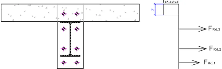
(2) In the article of J.Y. Richard Liew et al, the width of the concrete is taken as equal to the width of the column flange (beff,conn = bc) and the development of the concrete rods in compression through the “strut-and-tie” model is neglected.. Fig. 1. Plane view of the slab in the vicinity of the joint - development of concrete rods in compression under sagging moment The definition of the width given in [2] is used in the developed procedure as this definition reflects in a more appropriate way the mechanism developing in the concrete slab according to the observations reported during experimental tests ([2] and [4]). Another difference between the two methods is linked to the definition of the height of concrete to be considered and, accordingly, to the position of the centre of compression within the joint. In [2], the centre of compression is assumed to be at mid-height of the concrete slab while in [3], the following procedure is given to compute the position of this point: - the characterisation of the components in tension and eventually in shear is performed according to the rules recommended in the Eurocodes; - then, the height of the concrete/composite slab contributing to the joint behaviour is computed by expressing the equilibrium of the load developing in the concrete/composite slab in compression with the components in tension or in shear and assuming a rectangular stress distribution in the concrete (equal to 0,85 fck/γc in a design). For instance, in the example illustrated in Fig. 2, the concrete height to be considered is equal to: z=. -. FRd ,1 + FRd ,2 + FRd ,3 beff ,conn .(0,85. f ck / γ c ). ≤ hconcrete. where hconcrete is the total height of the concrete slab (in case of a composite slab, hconcrete is equal to the concrete above the ribs); finally, the characterisation of the joint is performed assuming that the centre of compression is situated at the middle of the height of the contributing part of the concrete slab (z). Z. f ck,actual. F Rd,3 F Rd,2 F Rd,1. Fig. 2. Height of the concrete to be considered in the characterisation of the new component It is the latter procedure which is considered in the proposed method as it reflects in a more appropriate way the actual behaviour of the joint according to the observations made during experimental tests [4]. So, the resistance of the component “concrete slab in compression” can be computed through the following formula: FRd,CSC = beff,conn.z.(0,85.fck/γc).
(3) The two previously mentioned references only deal with the characterisation of the component “concrete slab in compression” in term of resistance but no formulas are proposed to characterise the latter in term of stiffness; however, the latter is requested in order to be able to predict the initial stiffness of the joint (and to derive the moment-rotation curve). If reference is made to [5] a formula is proposed to predict the stiffness of a concrete block against a rigid plate. In the present case, the steel column encased in the concrete slab can be considered as a rigid plate; so, the formula proposed in [5] can be extended to the present situation to compute the stiffness of the component under consideration: kcsc =. Ec . beff ,conn .z. 1, 275.Ea where EC is the secant Young modulus for the concrete, Ea, the elastic Young modulus for the steel and kCSC, the stiffness of the component “concrete slab in compression” to be considered in the component method. In [4], the so-defined analytical procedure is validated through comparisons with results from experimental tests performed on composite joints in isolation. An example of such comparison is presented in Fig. 3 where the analytical prediction is compared to results obtained at Trento University [6] through experimental tests conducted on external composite joints (see Fig. 4) within a European RFCS project called PRECIOUS in which Liège University and ArcelorMittal Long Products were also involved. Within the analytical computations, the actual material properties (without safety factors), determined through coupon tests for the steel materials and through cylinder compression tests for the concrete, are used. The resistant bending moment MRd and the initial stiffness Sj,ini are computed in full agreement with the component method recommended in the Eurocodes while the ultimate moment Mu, the post-limit stiffness Sj,post-limit and the rotation capacity φu are computed according to the method proposed in the PhD thesis of Jean-Pierre Jaspart [7] (which is in full agreement with the component method), as no methods are actually proposed in the codes to compute these properties. In Fig. 3, it can be observed that two experimental curves are reported. They are distinguished by the configuration of the slab: the TEST 2 joint is composed of a composite slab while the TEST 3 one is composed of a concrete slab. From the comparison presented in Fig. 3, it can be observed that a very good agreement is obtained between the analytical prediction and the experimental results. For TEST 2, a loss of resistance in the joint is observed at a rotation of 29 mrad what is not reflected by the analytical prediction. In fact, this loss of resistance during the test was associated to a lack of ductility of the concrete in the vicinity of the connection, phenomenon not yet covered by the proposed analytical procedure. Mom ent at the joint [kN m ]. 500 400 300. Experimental result_TEST 2. 200. Experimental result_TEST 3. 100. Component method prediction with the new component 0 0. 10. 20. 30. 40. 50. 60. 70. 80. 90. Joint rotation [mrad]. Fig. 3. Comparisons analytical prediction vs. experimental results [4].
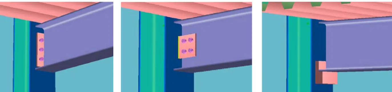
(4) TEST 3 2970. 150. TEST 2 IPE300 HEB260 2440. Fig. 4. Tested joint configurations at Trento University [6] 2. DEVELOPED DESIGN DEDICATED SOFTWARE. 2.1 General information and scope. A user-friendly software tool has been developed in order to make the application of the Eurocode 4 design rules for composite joints more easy for the designer. The software is a special edition of the new version of the well known commercial software CoP (CoP stands for Connection Program). The software is developed by Feldmann + Weynand GmbH in cooperation with the University of Liège. The development has been supported by ArcelorMittal and this special edition is provided free of charge [8]. The ArcelorMittal edition of CoP includes also a so-called light version of the CoP steel modules. However this light version is rather limited in scope compared to the full version of CoP. For more information, reference is made to the CoP web site [9]. The following paragraphs give a short summary of the scope of the special edition and some screen shots are shown. CoP is a standard Windows software for the design of joints in steel and steel-concrete composite building frames according to Eurocode 3 (EN 1993) and Eurocode 4 (EN 1994). The ArcelorMittal edition is an unprotected module of CoP which allows the user to design standard joints in composite constructions. A car park for example would be a typical application.. Fig. 5. Example of connection types in the CoP ArcelorMittal edition CoP considers various types of connections (such as bolted end-plate connection, double web cleats, header plates, fin plates) as well as various joint configurations (such as single sided beamto-column joint configurations, double sided beam-to-column joint configurations, single sided beam-to-beam joint configurations, double sided beam-to-beam joint configurations). Figure 5 shows some examples of connection types of a beam-to-column joint configuration with a composite beam section. The software consists of three main modules: (a) the user interface, (b) the calculation module and (c) the output processor. These main modules are described more in detail hereafter..
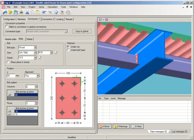
(5) 2.2 User interface. An easy-to-use and simple user interface is provided in order to input all necessary data to describe the geometry and the material properties of the joints, see Figure 6. The ArcelorMittal edition is available in English, French and German language.. Fig. 6. Main screen of CoP. Fig. 7. Input screen for composite beam sections Individual joints may be specified by entering the member and connection data. A complete database containing profile and material characteristics is included in the software in order to.
(6) facilitate the data input, see for example the data input screen for a composite beam section in Figure 7. During the data input, a data check module is observing the consistency and validity of the data and it informs the user immediately about missing or wrong data. Furthermore, scaled 2D drawings and a 3D visualisation give the user an immediate feed-back about the current data input. 2.3 Calculation modules. The CoP calculation modules are designed to work with the component method. When the user runs the calculation module, either for the active joint or for all defined joints, the structural properties are calculated and a check of the resistance against the internal forces acting at the joint is made. 2.4 Output processor. Finally, CoP will generate a calculation note containing the data input, all results of the calculation of the joint properties and the design checks which are performed if internal loads (effects) are given. The language of the calculation note may be different from that of the user interface. 3. CONCLUSIONS. The analytical procedure to characterise the behaviour of composite joints, as actually proposed within the Eurocodes, is not yet able to cover the case of composite joints subjected to sagging bending moments. Within the present paper, an analytical method to predict the response of composite joint subjected to such loadings has been first described. Furthermore, a software tool for the design of composite joints according to Eurocode 4 is presented. The software is provided free of charge by ArcelorMittal. REFERENCES. [1] Demonceau J.F., Luu N.N.H. and Jaspart J.P., Development of membranar effects in frame beams: experimental and analytical investigations, Eurosteel 2008 conference, Graz, Austria, 2008. [2] Ferrario F., Analysis and modelling of the seismic behaviour of high ductility steel-concrete composite structures, PhD thesis presented at Trento University, 2004. [3] Liew R.J.Y., Teo T.H. and Shanmugam N.E., Composite joints subject to reversal of loading – Part 2: analytical assessments, Journal of Constructional Steel Research, pp. 247-268, 2004. [4] Demonceau J.-F., Steel and composite building frames: sway response under conventional loading and development of membranar effects in beams further to an exceptional action, PhD thesis presented at Liège University, 2008. [5] Weynand K., Column bases in steel building frames. COST C1 – Semi-rigid behaviour of civil engineering structural connections, Luxembourg, 1999. [6] Trento University. Partially reinforced-concrete-encased column joints for severe seismic loadings: tests and main results, Internal report for the RFCS project RFS-CR-03034 “Prefabricated composite beam-to-column filled tube or partially reinforced-concrete-encased column connections for severe seismic and fire loadings”, March 2006. [7] Jaspart J.P.. Study of the semi-rigidity of beam-to-column joints and its influence on the resistance and stability of steel buildings. PhD thesis, Liège University, 1991 (in French). [8] Weynand K., Klinkhammer R., Oerder R. , Jaspart J.-P. , CoP ArcelorMittal Edition, Program for the design of joints according to EN 1994, www.arcelormittal.com/sections, 2008. [9] Weynand K., Klinkhammer R., Oerder R. , Jaspart J.-P., CoP - The Connection Program, Program for the design of joints according to EN 1993-1-8, www.fw-ing.de/software, 2008..
(7)
Figure
![Fig. 3. Comparisons analytical prediction vs. experimental results [4]](https://thumb-eu.123doks.com/thumbv2/123doknet/6540096.176052/3.892.264.669.897.1105/fig-comparisons-analytical-prediction-vs-experimental-results.webp)
Documents relatifs
Qualitatively different categories of descriptions concerning the meaning of evalua- ting technical solutions, performing a house hop and being able to act with presence
Chapter 1 is written by Lynne Cameron, who, after sketching the multidimensional status of metaphor, draws her readers’ attention towards the procedures and the steps to be taken
For a pair of semilinear PDEs in one space dimension ([T 2], [McLPT]) and for nonresonant systems of three such equations ([JMR 4]) the weak limit of the solution is determined by
For practical reason, this system is written using the vector potential A C of the incident laser field, the vector potential A R of the Raman component, the electric field
(3) Computer and network service providers are responsible for maintaining the security of the systems they operate.. They are further responsible for notifying
Exactly one OSINLCP packet is encapsulated in the Information field of a PPP Data Link Layer frame where the Protocol field indicates type hex 8023 (OSI Network
Although ISO 2022 specifies special additional escape sequences to indicate the use of revised character sets, it is suggested here not to make use of this special escape
They are the largest sector of the health care workforce; they play a critical role in health promotion, disease prevention and delivering primary and community care, but
