UNIVERSITÉ DE MONTRÉAL
DUALLY-POLARIZED MICROWAVE COMPONENTS BASED ON POLARIZATION-SELECTIVE COUPLING FOR GREEN WIRELESS SYSTEMS
AHMED SAKR
DÉPARTEMENT DE GÉNIE ÉLECTRIQUE ÉCOLE POLYTECHNIQUE DE MONTRÉAL
THÈSE PRÉSENTÉE EN VUE DE L’OBTENTION DU DIPLÔME DE PHILOSOPHIAE DOCTOR
(GÉNIE ÉLECTRIQUE) JUIN 2018
UNIVERSITÉ DE MONTRÉAL
ÉCOLE POLYTECHNIQUE DE MONTRÉAL
Cette thèse intitulée :
DUALLY-POLARIZED MICROWAVE COMPONENTS BASED ON POLARIZATION-SELECTIVE COUPLING FOR GREEN WIRELESS SYSTEMS
présentée par : SAKR Ahmed
en vue de l’obtention du diplôme de : Philosophiae Doctor a été dûment acceptée par le jury d’examen constitué de :
M. LAURIN Jean-Jacques, Ph. D., président
M. WU Ke, Ph. D., membre et directeur de recherche M. DJERAFI Tarek, Ph. D., membre
DEDICATION
iv
ACKNOWLEDGMENTS
I would never have been possible to finish my dissertation without the help of ALLAH. May ALLAH shower us always with his mercy and blessings. Amen! Above all, I would like to thank my mother for her personal support and great patience at all times. My father, brother, sisters and brother-in-law have given me their unequivocal support throughout, as always, for which my mere expression of thanks likewise does not suffice. I cannot find words that express my deepest gratitude to Dr. Walid Dyab, a postdoctoral fellow in our group. Honestly speaking and without any hesitation, I would say that the work of this dissertation could not be accomplished without his contribution. Dr. Dyab has a main contribution in every single point presented in this dissertation. My greatest thanks goes to him. After two years of working together, I believe Dr. Dyab is an outstanding researcher and rising research star. He has manifested a very high level of creativity in scientific research. Foremost among, I extend my sincere and deepest gratitude to my research advisor, Prof. Ke Wu, for his excellent guidance, caring, patience, and providing me with an excellent atmosphere for doing research. It is a great experience to work under the supervision of Prof. Wu with his well-known outstanding academic records. This increased my responsibilities and accordingly my motivation to meet his expectations from my side. I wish I did so! Our published journals would not have been possible without his experience and instructions. I have also taken a graduate course with Prof. Wu that greatly enhanced my knowledge in electromagnetics. The good advice, support, and friendship of Prof. Wu, has been invaluable on both an academic and a personal level, for which I am extremely grateful. His enthusiasm and passion to our work have always motivated me to work harder. I am very thankful to my advisor. I would like to acknowledge the financial, academic and technical support of PERSWADE in the award of a postgraduate scholarship. I would like to thank all the technical staffs of Poly-Grames Research Center and the administration staff as well. I also take this opportunity to express a deep sense of gratitude to Mr. Ossama Elmogy, Dr. Ahmed Sadek, Dr. Ahmed Korashy, Ahmed Medhat, Adham Ismail and Zaki Ajabi on the personal level, the discussions with them were really invaluable and shared in supporting me during my PhD studies and for the enjoyable times that we spent together throughout my PhD. Last, but no means least, I thank my master advisor Prof. Alaa Abdelmageed, my friends Islam Hashem, Tarek Ameen, Mohamed Zaghloul, Amr Mahmoud, and Ahmed Elshaikh for their support and encouragement. For any errors or inadequacies that may remain in this work, of course, the responsibility is entirely my own.
RÉSUMÉ
Avec le développement rapide et continu de technologies et de réseaux sans fil de nouvelle génération tels que la 5G et avec les ressources limitées d'énergie et de spectre disponibles pour soutenir ces développements sans fil rapides, l'exploration des bandes millimétriques sous-utilisées devient incontournable. Il devient de plus en plus crucial de se concentrer sur la réduction de la consommation d'énergie dans les futurs systèmes sans fil. Le moyen le plus efficace de réception d'énergie d'onde électromagnétique est de capturer complètement les deux composantes orthogonales de son vecteur de champ de propagation en relation avec la diversité de polarisation. De plus, l'utilisation d'ondes bi-polarisées permet l'amélioration d'une capacité de transmission via la réception simultanée de deux canaux orthogonaux. Cette thèse montre comment proposer et exploiter le concept très original de la diversité de polarisation sur la bande de fréquences mmW qui a été assignée aux applications sans fil. Auparavant, la diversité de polarisation était mise en œuvre dans des profils non planaires, ce qui compliquait son intégration avec l'application de carte de circuit imprimé (PCB). Par conséquent, la motivation principale de cette thèse est de mettre en œuvre la diversité de polarisation dans les profils planaires aux bandes de fréquence récemment assignées autour de 28 GHz et 38 GHz pour être intégrée dans la cinquième génération (5G) de communication sans fil.
Ceci est fait en développant la théorie du fonctionnement et de la procédure de conception des composants MMW à double polarisation. La nouveauté présentée dans ce travail de thèse réside dans le développement d'un principe de fonctionnement permettant de concevoir et de mettre en évidence une classe de composants mmW bi-polarisés, à savoir les coupleurs 3dB, les coupleurs 0dB et les déphaseurs. Cela permet le développement de réseaux de formation de faisceau bi-polarisés tels que la matrice de Butler et les systèmes de télédétection à polarisation, basés sur une jonction à six ports à double polarisation. Une procédure de conception analytique complète est présentée avec des vérifications à travers des simulations pleine onde et des mesures de prototypes. La diversité de polarisation a été un facteur essentiel dans la performance et l'amélioration de la capacité de divers systèmes sans fil, y compris les réseaux cellulaires. Par conséquent, la conception et le développement de structures d'alimentation d'antenne bi-polarisées dans la bande mmW sont indispensables. Tout d'abord, en tant que dispositif bipolaire de base, une conception de transducteur orthomode compact (OMT) dans la bande Ka est proposée. La nouveauté de l'OMT
vi proposée découle d'un concept distinct de traitement des signaux bi-polarisés basés sur un coupleur sélectif de polarisation (PSC). La théorie du PSC est développée et comprise à travers l'analyse de ses guides d'ondes constitutifs. De tels guides d'ondes sont des formes hybrides de guide d'ondes diélectrique non radiatif intégré au substrat (SINRD) et de guide d'ondes intégré au substrat (SIW). Une procédure analytique basée sur le terrain est ensuite présentée et développée pour une modélisation précise des paramètres effectifs du guide d'onde SINRD. Ce modèle est basé sur l'analyse de mode propre d'un matériau de substrat diélectrique perforé avec des trous d'air et enfermé entre deux plaques métalliques horizontales. A partir de ce modèle, on trouve que la constante diélectrique effective résultante d'une géométrie périodique du guide d'onde SINRD dépend de la direction d'un vecteur de champ électrique par rapport à la périodicité du matériau. En d'autres termes, les parties guidantes des guides d'onde SINRD agissent comme des matériaux anisotropes. Le modèle proposé fournit un schéma pour l'isotropisation des substrats anisotropes. Ceci est en plus de clarifier les régimes exacts de fonctionnement à l'intérieur du guide d'onde SINRD basé sur le mécanisme de guidage.
PSC pourrait alors être réalisé dans les structures intégrées en raison de différents mécanismes par lesquels les modes orientés orthogonalement sont guidés. Des niveaux de couplage théoriques de 0 dB sont possibles dans la structure conçue. L'analyse analytique et les étapes de conception sont détaillées. Cette analyse facilite un contrôle complet de l'opération monomode pour chaque polarisation. Ce contrôle, outre que la structure est plane, représente les principaux avantages de la structure proposée. Ensuite, un prototype est mis en œuvre et mesuré où un excellent accord est obtenu avec les résultats de la simulation. Un modèle de circuit équivalent est déduit pour la modélisation des caractéristiques de dispersion du PSC. Par conséquent, des méthodologies de conception soutenues par une étude théorique complète et une analyse de simulation pour un OMT basé sur la PSC sont élaborées et examinées.
La conception générale d'un OMT à base de PSC dépend essentiellement d'un guide d'ondes de coupleur de plaque diélectrique avec une paroi de polariseur PEC périodique en son milieu. En d'autres termes, la structure PSC peut être considérée comme deux guides d'ondes fusionnés en parallèle. Lorsque l'un des guides d'ondes est excité par une onde bi-polarisée, la polarisation verticale reste dans le guide d'onde excité tandis que la polarisation horizontale est entièrement couplée à l'autre. Des limitations pratiques pour cette conception sont discutées et supportées avec
des solutions utilisant un coupleur de fente supérieur proposé au lieu du coupleur de dalle diélectrique. Des équations de forme fermée sont obtenues en tant que recettes de conception pour calculer les dimensions de la structure et la largeur de bande en fonction de la fréquence de fonctionnement et des paramètres du matériau. La structure proposée est prototypée et mesurée. En tant qu'application, une jonction à six ports est développée sur la base de la PSC. Le six ports est le module le plus fondamental pour développer des émetteurs-récepteurs interférométriques. Cette jonction est présentée dans cette thèse sous une nouvelle forme. Dans la nouvelle forme, la jonction à six ports applique sa fonctionnalité sur deux polarisations orthogonales simultanément. La jonction à six ports bi-polarisés est inventée en ajoutant la caractéristique bi-polarisée à chacun de ses composants constitutifs, à savoir les diviseurs de puissance, les coupleurs hybrides 3dB et les déphaseurs à courbure circulaire. Ces composants sont étudiés analytiquement et ré-inventés pour être bi-polarisés en utilisant le concept de PSC susmentionné. La jonction à six ports doublement polarisée est prototypée et mesurée. De même, un dispositif de matrice de Butler à double polarisation est mis en œuvre sur la base du PSC approprié pour des applications de formation de faisceau.
viii
ABSTRACT
With the rapid and continuous development of new generation wireless technologies and networks such as 5G and with the limited enabling energy and spectrum resources available in support of such fast-moving wireless developments, exploring the underutilized millimeter-wave (mmW) bands becomes inescapable. It becomes more and more crucial to focus on the reduction of energy use in future wireless systems. The most efficient way of electromagnetic wave energy reception is to fully capture the two orthogonal components of its propagating field vector in connection with polarization diversity. In addition, the use of dually-polarized waves allows the enhancement of a transmission capability via the simultaneous reception of two orthogonal channels. This thesis shows how to propose and exploit the highly original concept of polarization diversity over the mmW frequency band which has been assigned for wireless applications. Previously, the polarization diversity was implemented within non-planar profiles which complicates its integration with the printed circuit board (PCB) application. Therefore, the main motivation of this thesis is to implement the polarization diversity within planar profiles at the recently assigned frequency bands around 28 GHz and 38 GHz to be suitable for integration in the fifth generation (5G) of wireless communication.
This is done by developing the theory of operation and design procedure of dually-polarized mmW components. The novelty presented in this thesis work lies in developing a principle of operation to come up with the design and demonstration of a class of dually-polarized mmW components, namely 3dB couplers, 0dB couplers and phase shifters. This allows the development of dually-polarized beamforming networks such as Butler matrix and polarization-inclusive remote sensing systems based on a dually-polarized six-port junction. A full analytical design procedure is presented with verifications through full-wave simulations and prototype measurements.
Polarization diversity has been an essential factor in the performance and capacity enhancement of various wireless systems including cellular networks. Accordingly, the design and development of dually-polarized antenna feeding structures in the mmW band is a must. Firstly, as the basic dual-polarized device, a compact orthomode transducer (OMT) design in the Ka-band is proposed. The novelty of the proposed OMT stems from a distinct concept of handling dually-polarized signals based on a polarization selective coupler (PSC). The theory of PSC is developed and understood
through the analysis of its constituent waveguides. Such waveguides are hybrid forms of substrate integrated nonradiative dielectric (SINRD) waveguide and substrate integrated waveguide (SIW). A field-based analytical procedure is then presented and developed for accurate modelling of the effective parameters of SINRD waveguide. This model is based on the eigenmode analysis of a dielectric substrate material perforated with air-holes and enclosed between two horizontal metallic plates. From this model, it is found that the resulting effective dielectric constant of a periodic geometry of the SINRD waveguide is dependent on the direction of an electric field vector with respect to the material periodicity. In other words, the guiding parts of the SINRD waveguides act as anisotropic materials. The proposed model provides a scheme for the isotropization of anisotropic substrates. This is in addition to clarifying the exact regimes of operation inside the SINRD waveguide based on the guiding mechanism.
PSC could then be realized in the integrated structures due to different mechanisms by which orthogonally oriented modes are guided. Theoretical coupling levels of 0dB are possible in the designed structure. Theoretical analysis and design steps are given in details. This analysis facilitates a complete control on the single mode operation for each polarization. Besides the structure being planar, this control represents the main advantages of the proposed structure. Then, a prototype is implemented and measured where an excellent agreement is achieved with the simulation results. An equivalent circuit model is deduced for modeling dispersion characteristics of the PSC. Consequently, design methodologies supported through comprehensive theoretical study and simulation analysis for a PSC-based OMT are developed and examined.
The general design of a PSC-based OMT basically depends on a dielectric slab coupler waveguide with a longitudinal periodic PEC polarizer wall in its middle. In other words, The PSC structure can be considered as two waveguides which are fused together in parallel. When one of the waveguides is excited by a dually-polarized wave, the vertical polarization remains in the excited waveguide while the horizontal polarization is fully coupled to the other one. Practical limitations of this design are discussed and supported by solutions using a proposed top slot coupler instead of the dielectric slab coupler. Closed-form equations are obtained as design recipes for computing structure dimensions and bandwidth based on operating frequency and the material parameters. The proposed structure is prototyped and measured.
x As an application, a six-port junction is developed based on the PSC. The six-port is the most fundamental module for developing interferometric transceivers. This junction is presented in this thesis in a new form. In the new form, the six-port junction applies its functionality on two orthogonal polarizations simultaneously. The dually-polarized six-port junction is invented by adding the dually-polarized feature to each of its constituent components, namely the power dividers, the hybrid 3dB couplers and the circularly-bent phase shifters. These components are analytically studied and re-invented to be dually-polarized using the aforementioned PSC concept. The dually-polarized six-port junction is prototyped and measured. Similarly, a dually-polarized Butler matrix device is implemented based on the PSC suitable for beamforming applications.
TABLE OF CONTENTS
DEDICATION ... III ACKNOWLEDGMENTS ... IV RÉSUMÉ ... V ABSTRACT ... VIII LIST OF FIGURES ... XIV LIST OF SYMBOLS AND ABBREVIATIONS... XXI LIST OF APPENDICES ... XXIII
CHAPTER 1 INTRODUCTION ... 1
1.1 General Discussion ... 1
1.2 State-of-the-art of Polarization Diversity ... 4
1.3 Thesis organization ... 8
CHAPTER 2 SPECIAL DUALLY-POLARIZED INTEGRATED WAVEGUIDES ... 9
2.1 SIW guiding structures for polarization diversity ... 10
2.2 NRD guiding structures and its image form... 12
2.2.1 Modelling Effective Anisotropy of SINRD Waveguide ... 14
2.2.2 Integrated NRD Waveguide ... 32
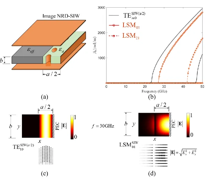
2.2.3 Image-NRD waveguide ... 36
2.3 Hybrid NRD-SIW guiding structure and its image form ... 37
2.3.1 Hybrid NRD-SIW waveguide ... 38
2.3.2 Image-NRD-SIW waveguide ... 39
2.4 Conclusion and design rules discussion ... 41
xii
3.1 Polarization selective coupling (PSC) ... 44
3.1.1 Image-NRD coupler ... 44
3.1.2 The Concept of Polarization Selectivity for Polarization Discrimination ... 50
3.1.3 Validation of the Isotropization Concept using PSC ... 55
3.1.4 Orthomode Transducer design based on Polarization Selective Coupler ... 58
3.2 Effective polarization independent coupling (EPIC) ... 76
3.2.1 EPIC Operation ... 76
3.2.2 Controllability of the Dielectric Constant ... 78
3.2.3 Results and Discussions ... 80
3.3 Conclusion ... 81
CHAPTER 4 APPLICATIONS – PLANAR DUAL-POLARIZED PSC-BASED MICROWAVE COMPONENTS ... 83
4.1 Polarization Selective Coupling ... 86
4.2 Dual-polarized power divider ... 88
4.3 Dual-polarized hybrid coupler ... 90
4.4 Waveguide bend for dual-polarization phase equalization ... 92
4.5 Dually-polarized six-port junction ... 96
4.6 Operation principle of dually-polarized Butler matrix ... 102
4.6.1 Dually-polarized couplers with dual-phase-shifts ... 104
4.6.2 Dually-Polarized Phase Shifter ... 110
4.6.3 The Complete Dually Polarized Butler Matrix ... 113
4.7 Conclusion ... 122
CHAPTER 5 INTEGRATED POLARIZATION CONVERTER FOR PLANAR CROSS-POLARIZED MILLIMETER WAVE COMPONENTS ... 123
5.2 Field Rotation in Uniaxial Media: Wave-Plates ... 125 5.3 Design Methodology and Performance Analysis of Uniaxial Polarization Converter 126 5.4 Prototype of an Integrated Planar Mode Converter ... 128 CHAPTER 6 CONCLUSION AND RECOMMENDATIONS ... 132 BIBLIOGRAPHY ... 136
xiv
LIST OF FIGURES
Figure 1.1: Signal transmission-reception procedure in the downlink (base station to handset) of current wireless communication systems, and the proposed greening technology. ... 2 Figure 1.2: Conceptual block diagram for Ka-band dually polarized base-station antenna feeding
system ... 6 Figure 2.1. Cross-comparison of SIW cross-sectional dimensions in the mmW range. ... 11 Figure 2.2. Physical structure of a two-dimensional periodic medium and its unit cell. ... 14 Figure 2.3. Theoretical and simulation dispersion curves for the first two modes of the periodic
medium in Figure 2.2 at i=0. ... 18 Figure 2.4. Theoretical and simulation field distributions for the first two modes of the periodic
medium in Figure 2.2 at i=0. ... 19 Figure 2.5. Physical structure a two-dimensional double periodic medium with its unit cell. ... 21 Figure 2.6. The calculated cross-sectional spatial relative permittivity based on (13). ... 21 Figure 2.7. Theoretical and simulation dispersion curves for the first two modes of the periodic
medium in Figure 2.5 at i=0. ... 22 Figure 2.8. Theoretical and simulation field distributions for the first two modes of the periodic
medium in Figure 2.5 at i=0. ... 23 Figure 2.9. Validation example for the eigenmode analysis of a two-dimensional periodic medium:
(a) waveguide structure, (b) field distribution, (c) magnitude of scattering parameters and (d) propagation constant. ... 24 Figure 2.10. Validation example for the isotropization using periodic medium: (a) magnitude of
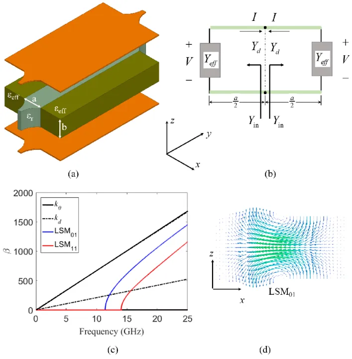
the scattering parameters and (b) propagation constant. ... 27 Figure 2.11. Nonradiative dielectric waveguide: (a) equivalent structure, (b) equivalent circuit
model, (c) dispersion curves for horizontally oriented modes and (d) field vector distribution for LSM01 mode. ... 28
Figure 2.12. SINRD waveguide: (a) equivalent structure, (b) effective dielectric constant for the periodic medium, field distribution for LSM01 mode at (c) 20 GHz, (d) 26 GHz and (e) 35 GHz. ... 30 Figure 2.13. NRD waveguide: (a) equivalent structure and (b) equivalent circuit model. ... 33 Figure 2.14. NRD waveguide characteristics: (a) dispersion curves, (b) cross-sectional field
distribution of LSE00 mode and (c) LSM01 mode. ... 35 Figure 2.15. Image-NRD waveguide: (a) equivalent structure, (b) cross-sectional field distribution
of LSM01 mode and (c) dispersion curves. ... 37 Figure 2.16. Hybrid-NRD-SIW waveguide: (a) equivalent structure and (b) dispersion curves. .. 39 Figure 2.17. Image-NRD-SIW waveguide: (a) equivalent structure, (b) dispersion curves, (c) field
distribution of TE10 mode and (d) field distribution of LSM01 mode. ... 40 Figure 3.1. Image-NRD coupler: (a) equivalent structure, (b) equivalent circuit model and (c)
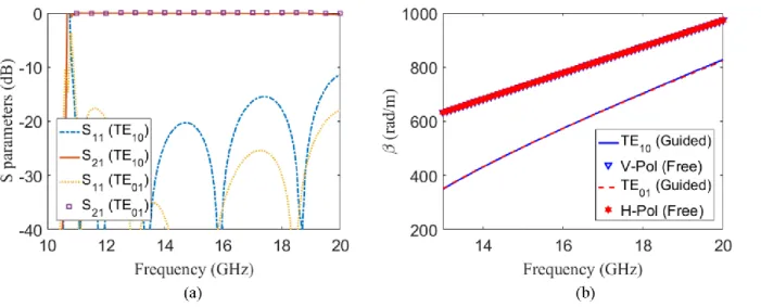
dispersion curves. ... 45 Figure 3.2. Field characteristics of image-NRD coupler at 38 GHz: (a) field distribution of LSE10
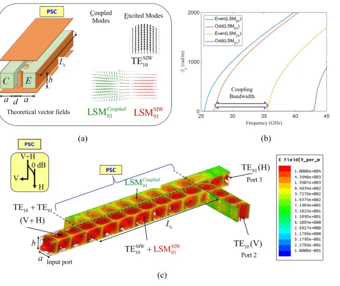
mode, (b) power alternation for LSE10 mode, (c) field distribution of LSM01 mode and (d) power alternation for LSM01 mode. ... 47 Figure 3.3. Polarization selective coupler (PSC): (a) equivalent structure supported with theoretical
field vectors for the excited and coupled modes, (b) dispersion curves of horizontally polarized modes and (c) field distribution when adding input and output waveguides. ... 49 Figure 3.4. The parametric analysis for both of (a) the spacing d and (b) the coupling length Lc of
the PSC-based OMT design. ... 52 Figure 3.5. The scattering parameters with field distributions at the input and output ports for the
PSC-based OMT for the vertically polarized TE10 mode (Mode1) and the horizontally polarized TE01 mode (Mode2). ... 54 Figure 3.6. (a) Polarization selective coupler (PSC), (b) dispersion curves for the common
waveguide, (c) full coupling length versus frequency and (d) field distribution in the PSC at 38 GHz. ... 56 Figure 3.7. Magnitude of scattering parameters for (a) TE10 mode and (b) TE01 mode. ... 58
xvi Figure 3.8. Different views for the general form of a dielectric-filled PSC-based OMT shown in elevation, side view, plan, and isometric cuts. ... 59 Figure 3.9. PSC-based OMT filled with an anisotropic dielectric material (Roger RT/Duroid 6010):
(a) dispersion curves, (b) full coupling length versus frequency, (c) field distribution and (d) simulated S parameters. ... 62 Figure 3.10. PSC-based OMT filled with isotropic dielectric material (Roger 6002) (a) prototype
and (b) measured versus simulated S parameters of the coupled mode TE01. Coupling length Lc = 21 mm, optimized matching length Lm=9.2 mm and the waveguide cross-section. ... 65 Figure 3.11. PSC-based OMT prototype: (a) the dielectric substrate, (b) the metallic enclosure and
(c) the overall structure. ... 68 Figure 3.12. Scattering parameters for the PSC-based OMT integrated with a square horn antenna
(a) simulation and (b) measurements. ... 69 Figure 3.13. Simulated and measured antenna gain at 37 GHz for different excitations: (a) port1:
azimuth cut, (b) port 2: azimuth cut, (c) port 1: elevation cut and (d) port 2: elevation cut. . 70 Figure 3.14. Air-filled PSC-based OMT integrated with horn antenna: (a) isotropic view of the
design (b) implemented prototype and (c) measurement setup in antenna anechoic chamber. ... 71 Figure 3.15. Performance analysis of the structure shown in Figure 3.14: (a) simulated field
distribution in the receiving case. The polarization state of the incoming wave is arbitrarily chosen to be circular and (b) measured and simulated S parameters in the transmission case. ... 74 Figure 3.16. Simulated and measured results at (a) port 1: azimuth cut, (b) port 2: azimuth cut, (c)
port 1: elevation cut and (d) port 2: elevation cut. ... 75 Figure 3.17. Effective polarization-independent coupler (EPIC): (a) general isometric view with its
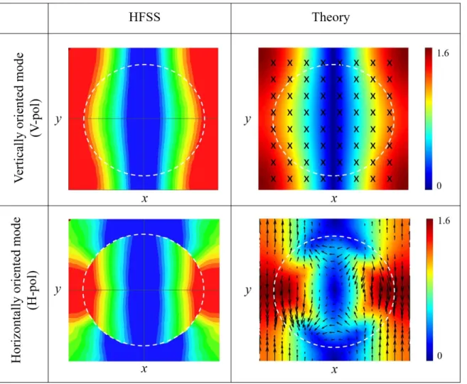
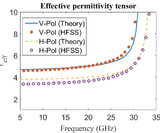
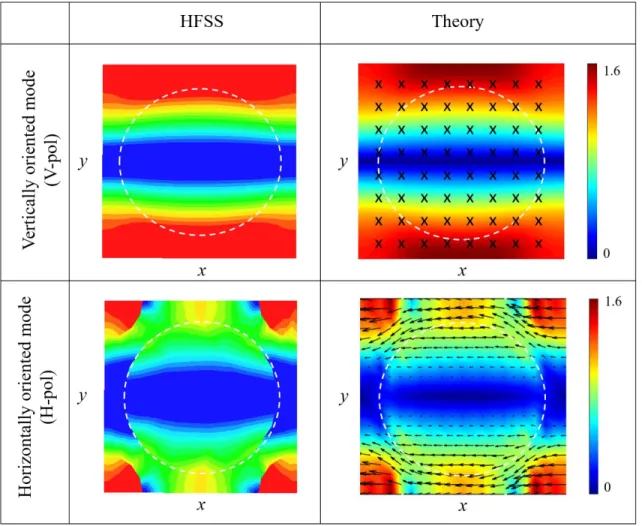
symbol, (b) effective permittivity tensor of a Rogers/duroid 6002 substrate perforated with air holes having the unit cell distribution in Figure 2.2 where r0.2 mm and p0.8 mm, (c) dispersion curves of the common waveguide when an effective material with the permittivity tensor in Figure 3.17 (b) fills the waveguide structure in Figure 3.17 (a), and (d) coupling lengths for the vertical and horizontal polarizations with the ratio between them. ... 77
Figure 3.18. Effective polarization independent coupler (EPIC): (a) Physical prototype, (b) effective homogeneous permittivity tensor, (c) scattering parameters of the TE10 mode, (d) scattering parameters of the TE01 mode and (e) field distribution of the two modes. ... 79 Figure 4.1. Conceptual block diagram for dually-polarized microwave components based on PSC
versus typical microwave components. ... 84 Figure 4.2. Polarization selective coupler (PSC): (a) isometric structural view and (b) dispersion
curves for horizontally polarized modes. ... 85 Figure 4.3. Dually-polarized power divider based on PSC: (a) equivalent structure, (b) field
distribution, (c) magnitude of scattering parameters for TE10 mode, (d) phase of scattering parameters for TE10 mode, (e) magnitude of scattering parameters for TE01 mode and (f) phase of scattering parameters for TE01 mode. ... 88 Figure 4.4. Dually-polarized hybrid coupler based on PSC: (a) equivalent structure, (b) field
distribution, (c) prototype, (d) magnitude of scattering parameters for TE10 mode, (e) magnitude of scattering parameters for TE01 mode and (f) phase of scattering parameters for both of the TE10 and TE01 modes. ... 90 Figure 4.5. Phase shift bend equalizer: (a) equivalent structure and (b) phase difference between
port 1 and port 2 for both of the TE10 and TE01 resulted from theory and HFSS simulation. 93 Figure 4.6. Polarization-inclusive remote sensing (PIRS) as a possible application for the dually-polarized six-port junction. ... 95 Figure 4.7. Dually-polarized six-port junction based on PSC: (a) block diagram with the ideal
theoretical scattering parameters and (b) the overall equivalent structure. ... 97 Figure 4.8. (a) Phase shift variation for the TE10 and TE01 modes due to a circular bend versus its
inner radius and (b) phase difference variation between two circular bends versus frequency. ... 99 Figure 4.9. Prototype of a dual-polarized six-port junction based on PSC: (a) overall structure and
(b) transition to WR28 waveguide. ... 100 Figure 4.10. Scattering parameters of dually-polarized six-port junction, simulation is solid line
xviii magnitude when exciting TE01 from port 1 (c) magnitude when exciting TE10 from port 2 (d) magnitude when exciting TE01 from port 2 (e) phase when exciting TE10 from port 1 and port 2, (f) phase when exciting TE01 from port 1 and port 2. ... 101 Figure 4.11. Dually-polarized Butler matrix, (a) Architecture of a base-station (BS) incorporating
a dually-polarized 4-by-4 Butler matrix and (b) the structure of its internal components. .. 102 Figure 4.12. Geometry of the proposed dually-polarized waveguide coupler made of metal and
filled with arbitrary dielectric. The circular pins with diameter, g, are made of metal. ... 105 Figure 4.13. Design of dually-polarized couplers, (a) dispersion curves of the common waveguide
section, (b) S-parameters and field distribution of the vertically-polarized mode in a coupler, (c) S-parameters and field distribution of the horizontally-polarized mode in a 3dB-coupler, (d) phase response of the 0dB coupler for the two polarizations, (e) S-parameters and field distribution of the vertically-polarized mode in a 0dB-coupler and (f) S-parameters and field distribution of the horizontally-polarized mode in a 0dB-coupler. ... 108 Figure 4.14. Dually-polarized phase shifter, (a) block diagram and principle of operation, (b)
detailed geometry of phase shifter and full-wave simulation results for the whole unit. .... 111 Figure 4.15. The complete assembly of the dually-polarized Butler matrix with detailed tabulated
dimensions of each component. Ports 5 to 8 can be connected directly to the radiating cross-polarized antennas. In the prototype shown in the next section, those ports are connected to a mirrored image of the four curved paths connected at the input ports 1 to 4. All ports are connected to WR-15 transitions via the matching section shown in the top left corner. The width, a=3.21mm, is made slightly larger than b=3.2mm to be able to differentiate between the modes numerically. ... 113 Figure 4.16. The complete prototype of the proposed dually-polarized Butler matrix, (a) Aluminum
block with the waveguide cavities engraved into it, (b) A transition from square waveguide to the standard WR15 transition, (c) Field distribution for the vertical polarization calculated on HFSS at 60 GHz and (d) horizontal polarization. ... 116 Figure 4.17. Measurement results of the prototype using Agilent vector network analyzer PNA-X
(b) port 2, (c) port 3, and (d) port 4 and by horizontal polarization at (e) port 1, (f) port 2, (g) port 3 and (h) port 4. The dashed lines represent the theoretical result to be achieved. ... 118 Figure 4.18. Progressive phase shift between the output ports of the dually polarized Butler matrix
when excited sequentially by vertical polarization at (a) port 1, (b) port 2, (c) port 3, (d) port 4, and by horizontal polarization at (e) port 1, (f) port 2, (g) port 3 and (h) port 4. The dashed lines represent the theoretical result to be achieved. ... 119 Figure 4.19. The array radiation pattern calculated based on the measured S-parameters (solid lines)
as compared to the theoretical pattern (dashed lines): (a) vertical polarization, and (b) horizontal polarization. ... 121 Figure 4.20. Performance of back-to-back square-to-WR15 transitions (S11 and S21) and the cross-talk between the two orthogonal polarizations within the fabricated network (Svh). ... 121 Figure 5.1. Block diagram of cross-polarized mmW printed circuits including the polarization
converter which is proposed in this dissertation. ... 124 Figure 5.2. Concept of field rotation in uniaxially anisotropic media, (a) Unbounded slab of
uniaxial medium, (b) Bounded slab of uniaxial medium enclosed by the metallic walls of a square waveguide. In the coordinate system of the waveguide, the material is called skew uniaxial dielectric [2] and (c) Artificially induced anisotropy and skewness in isotropic materials by tilted air-hole perforations. ... 125 Figure 5.3. Design procedure, simulation and fabrication of the polarization converter, (a)
Geometry of the air-hole perforations and the possible range of air-hole diameters limited by the technology used for drilling, (b) Maximum frequency below which the perforated medium can be modelled as an effective homogenous medium with a constant permittivity tensor, (c) Effective uniaxial permittivity versus perforation diameters, (d) Dispersion of a 2mm square waveguide filled with perforated RT/duroid6006 with period, p=0.9mm, d/p ratio of 0.5 and tilting angle of 45 degrees, (e) Setup for fabrication and (f) Electric field distribution and s-parameters of the prototype. ... 127 Figure 5.4. Structure of an approximate mode converter made of Rogers RT/duroid 6002. ... 129 Figure 5.5. Dispersion curves and field distribution for the ordinary and extraordinary modes for
xx Figure 5.6. The mode converter prototype and the setup for measurement. ... 131 Figure 5.7. The resultant scattering parameters. ... 131
LIST OF SYMBOLS AND ABBREVIATIONS
mmW Millimeter-Wave
RF Radio Frequency
PCB Printed Circuit Board 5G Fifth Generation LTE Long-Term Evolution OMT Orthomode Transducer
SIW Substrate Integrated Waveguide NRD Nonradiative Dielectric Waveguide
SINRD Substrate Integrated Nonradiative Dielectric Waveguide PSC Polarization-Selective Coupler
EPIC Effective Polarization-Independent Coupler FDTD Finite Difference Time Domain
VIE Volume Integral Equation PEC Perfect Electric Conductor
HFSS High-Frequency Structure Simulator TE Transverse Electric
TM Transverse Magnetic
V-Pol Vertical Polarization H-Pol Horizontal Polarization LSE Longitudinal Section Electric LSM Longitudinal Section Magnetic
ESIW Extended Substrate Integrated Waveguide VNA Vector Network Analyzer
xxii WR Waveguide Rectangular
CNC Computer Numerical Control
BW Bandwidth
PIRS Polarization-Inclusive Remote Sensing CPW Coplanar Waveguide
AF Array Factor
CMOS Complementary Metal-Oxide-Semiconductor IC Integrated Circuit
LIST OF APPENDICES
1
CHAPTER 1
INTRODUCTION
1.1 General Discussion
Data communication is expanding dramatically due to the growing demand for ever-increasing voice, video and data transmissions and mobile interactions. This increase inherently means higher energy consumption. This should be tackled by enhancing the transmission efficiency and power consumption of future wireless communication systems such as 5G and beyond. The proposed idea for the efficiency enhancement is the development of compact systems empowered by polarization
diversity, which provides a unique and alternative solution compared to all the existing techniques.
By definition, wireless systems communicate through electromagnetic wave propagation in air, free from any cables or physical or wired connections. The time varying behaviour of the tip of the electric field vector of the wave is called the wave polarization. Most of the terrestrial wireless systems utilize linearly polarized waves. In other words, they handle only one directional component of the received signal. The highest efficiency of wave reception occurs when the receiver is aligned with the incoming wave polarization. In mobile communications, we can never fully align the receiver with the incoming wave. This is because, in the terrestrial mobile channel, the wave suffers from different reflections, refractions, and diffractions. Therefore, current handsets of communication system depend on reception just on a single spatial component of the received electromagnetic field vector which is aligned with their integrated antenna. Statistically, this causes a waste of about fifty percent of the received signal energy. Previously, a typical solution to such situation is pumping more power from the transmitting base station in order to compensate for this possible loss at the handset receiver. This increase of power consumption could not be tolerated in the future green wireless systems, see Figure 1.1.
In the last few decades, wireless system designers have been more interested in solving the aforementioned problem by what is called Polarization Diversity receivers. These receivers consist of different antennas which are aligned with two orthogonal directions. Thus, whatever the orientation of the incoming wave, both of its components are received effectively. This has always been implemented on the uplink at the base stations only, and never on the downlink in the receiver handsets. This is due to the space requirements needed to mount two orthogonally polarized antennas and their supporting waveguides. Our idea is to develop and implement a new
Figure 1.1: Signal transmission-reception procedure in the downlink (base station to handset) of current wireless communication systems, and the proposed greening technology.
and compact polarization diversity technology suitable for integration in the receiver handsets as well, thus stopping the waste of energy that has been going on for decades.
The integration of polarization diversity, dual-polarization, in the mobile handsets is not an easy task. This is because all the circuits constituting any mobile system must be planar in order to undergo the printed circuit board (PCB) fabrication restrictions. On the other hand, the previous and current devices that allow handling dual-polarized signals are not planar in nature, and physically complicated which make their integration with the running mobile systems impossible. Therefore, implementing a planar dual-polarized circuit which can be integrated with the mobile systems will result directly in saving the wasted percent of the received energy. This is done by treating both of the orthogonal components of the received signal, and not only one component as before.
Briefly, the proposed idea presented in this dissertation mainly depends on using two different types of integrated waveguides combined together to form this newly invented technology for guiding millimeter-waves (mmW), which is supposed to deal with the frequency band of interest in the future wireless systems. In this technology, each type of waveguide is responsible for guiding and treating one component of the two orthogonal polarizations through two different field-polarized modes in those waveguides. Designed in a scientific and deliberate procedure, the
3 invented waveguides handle those orthogonal polarizations independently by means of the natural behavior of orthogonal signals, i.e. how each of the two components acts toward each used technology? For this newly invented technology, prototypes-based lab tests are held in the mmW band and show great potential in realizing the dually-polarized capability in many integrated microwave components. Empowered by those promising prototype tests, we seek renovation of all the current single polarized handheld devices and components. This renovation means to be dually-polarized instead of dealing with just one vector component, as shown in Figure 1.1. This is a real improvement of the energy efficiency as well as channel efficiency in the future wireless systems from our perspective.
Currently, most of the designers and researchers are looking forward to implementing various circuits in the mmW band which suits the next generation of mobile communication. In accordance with that, and with the potential of integrating the dual-polarization feature in the mmW circuits, it is highly required to add this feature in the transmitting and receiving circuitries of the communication systems and remote sensing applications. This will directly enhance the overall system efficiency and accordingly its capacity. Our responsibility is to raise and spread this issue globally and to share this technology with other researchers and developers. We should motivate and encourage all the interested specialists to consider the dual-polarization feature in their designs. In this case, the wasted percent of power in the un-received polarization of the signal will be used to enhance the system performance without the need of pumping more power or adding any complication to the existing systems.
The call for the fifth generation (5G) of mobile communications has already started, and many researchers worldwide are working hard toward the implementation of this new generation in order to create a wide range of wireless applications in the future. Keeping up with that and with our environmental constraints in mind, we call for this new communication systems to be the fifth in a generation, but the first in greenness. Greening the future communication systems, in our vision, is highly related to the optimum use of information in any signal. Integrated circuits empowered by the dually-polarized features will make it easy for the designers to increase the level of greenness in future wireless systems. Based on the previous general discussion, let’s move to a more technically specialized explanation for the proposed idea.
1.2 State-of-the-art of Polarization Diversity
A signal quality degradation caused by fluctuations in fading channels has been one of the greatest challenges facing the designers of mobile and cellular communication networks [1]. Since the late decades of the last century, receiving diversity techniques have presented reliable solutions for this challenge. Starting with the first generation of cellular communication and until the latest 4G LTE digital networks, base-stations have always involved one sort of signal diversity implemented [2]. Receiving diversity could be designed and made possible in the form of spatially separated antennas with inter-distance in the order of ten wavelengths. This is called spatial diversity. Another form of interest is polarization diversity achieved by having two orthogonally oriented receiving antennas. The previously mentioned types have widely been used since the development of the second generation of cellular networks, such as in the popular GSM networks. Multipath temporal diversity was also achieved and made possible using RAKE receivers in earlier code division multiple access networks [1].
The current generation of cellular networks including the state of the art 4G LTE networks still works in the frequency range 0.8-2.1 GHz [3]. This frequency range has proved suitable for terrestrial indoor/outdoor wave propagation with tolerable path loss and fading level. However, the existing and emerging demand for higher capacity techniques and more connected devices has urged the need to explore the underutilized 5-6 GHz band and beyond, for example, higher 28-38 GHz band. Since the latest band lies in the starting edge of the mmW band, new components, circuits and techniques have to be developed to cope with the development. Therefore, one of the most important functions of base-station antenna feeding structures remains to provide a polarization diversity capability in the mmW band. This function necessitates the existence of fully integrated dually-polarized microwave components.
Furthermore, with the current evolutionary growth of the mobile system and wireless communication demand, augmenting the capacity and the efficiency of such systems has become a stipulated research concern [1]. This required capacity enhancement should not be at the expense of a system bandwidth which is the main resource in a wireless communication system. Fortunately, mmW band with its broad bandwidth from 30 GHz to 300 GHz and beyond could be proposed as a candidate for the 5G network to fulfill the required wideband communication services [4, 5]. The importance of the mmW band comes in the company of drawbacks such as
5 propagation loss [6, 7] and multipath reflections from ground, buildings and other physical objects [8]. In order to achieve the highest possible exploitation of the mmW band, its efficiency must be boosted to overcome its drawbacks. One potential solution for that is the deployment of polarization diversity [2]. The polarization diversity has gained much interest in many applications; thanks to its capability in enhancing the efficiency of transmitting and/or receiving circuitries [9-11]. In particular, a backhaul/fronthaul point-to-point wireless links showed a great potential toward the 5G wireless communication [12].
The basic microwave component that can handle dually-polarized signal is called Orthomode Transducer (OMT). An OMT is a waveguide polarizer device with three physical ports. Its function is to separate or combine two spatially orthogonal signals within the same frequency band simultaneously. OMTs can hold many names as appear in the literature like Orthomode junctions, polarization diplexers, and dual-mode transducers.
Recently, OMTs have attracted growing interest, especially for integrated circuits, in dually-polarized systems. OMTs are commonly implemented to duplicate the capacity in modern communication systems within the same band of frequencies [13, 14]. They are essential components in remote sensing applications [15], satellite communications [16], multiple antenna systems [17, 18], and dually-polarized substrate integrated waveguide (SIW) systems [19].
There are many techniques to construct an OMT, but most of them are complicated and non-planar. This is because in those designs, the concept of separating and combining orthogonal signals is basically depends on structure geometry and internal transitions which are not the case in the proposed idea which depends on selective coupling as presented later. For a wideband operation, the Bøifot [20] and the turnstile junctions [21, 22] are the most common approaches. At high frequencies, a potter horn [23] has yielded good scattering parameters when used with an OMT device. In addition, a compact OMT for the band of 180-270 GHz [24] is implemented in split-block based on Bøifot as well. Some designs were based on symmetric reverse coupling as in [25, 26]. Many waveguide configurations have been used in the OMT design like tilted waveguide T-junction [27], septum polarizer [28], micro-machined transducer [29], platelet manufacturing strategy [30], single-ridged triangular waveguides [31], based on substrate integrated waveguide (SIW) technologies [32, 33] and based on turnstile junction using superimposition of three aluminum blocks [14].
Figure 1.2: Conceptual block diagram for Ka-band dually polarized base-station antenna feeding system
It is well known that planar microwave components are easier to fabricate and integrate with other components at low cost. Due to a large number of connected devices and hot spots targeted in the future 5G networks, the scope of this thesis focuses only on the planar designs such as the one reported in [19].
The substrate integrated waveguide design reported in [19] achieved some great advantages such as being planar and easy to fabricate. That design depends on exciting one waveguide with the two orthogonal modes to be separated. The mode separation is achieved by using two metallic vias which allow the propagation of the horizontally oriented mode and prevent the vertically oriented one. This vertical mode can then be extracted through a planar bend. In this thesis, we show a new
7 concept for mode separation suitable for OMT design in substrate integration technology. Thus, the idea presented in this thesis differs from that of [19] in terms of the mode separation mechanism. In the design introduced here, the mode separation is achieved by an evanescent coupling designed specifically for only one of the two modes to be separated. This is done by a deliberate combination between two different guiding mechanisms, the substrate integrated waveguide (SIW) and substrate integrated nonradiative dielectric waveguide (SINRD), together within one substrate. Each mechanism is responsible for guiding specific orientation of the electric field vector. The full demonstration and analysis of the modes propagation through such hybrid waveguide is presented in the following chapter.
The block diagram of the proposed OMT structure and its function in the base station of a cellular network is shown in Figure 1.2. This block diagram depicts a base-station antenna receiving an arbitrarily polarized wave. The function of the OMT is to collect the power received by the antenna and separate its two orthogonal field components. These two components are then delivered to the diversity combiner and the receiving circuitry independently.
The significant part of this thesis is about the design and analysis of the OMT block shown in Figure 1.2. The signal received by the antenna is fed into the OMT through a dual-mode guiding structure, which will involve the hybrid integration of two different modes guided by two different waveguides. This signal is then passed to a polarization-selective coupler (PSC). To the best of our knowledge, this PSC is based on a novel idea that has not been presented to date, hence the main contribution of this thesis. The PSC function is to fully couple or navigates one of the two orthogonal polarizations to a separate waveguide. After the two modes are separated, they are fed independently to vertically and horizontally oriented waveguides, and each is designed for single mode operation. Then each polarization is fed to the diversity combiner and the receiving circuitry as shown in Figure 1.2.
The main objective of this thesis is to develop the theory of PSC, and then apply it to the design of an mmW OMT integrated with a square horn antenna. This concept can then be applied to empower any microwave component with the dual-polarization feature as presented throughout the thesis chapters.
1.3 Thesis organization
This thesis focuses on the implementation of full-scale polarization diversity in integrated planar microwave components. This is presented firstly by introducing the main conceptual idea that is based on a unique polarization selective coupling (PSC). Based on this idea, dually-polarized microwave components are introduced accordingly and subsequently. The thesis is organized as follows:
Special forms of integrated waveguides that can handle dual-polarizations are studied in chapter 2. These forms are mainly based on the (SIW) and (SINRD) with their image forms. Then, the analysis and design of the separation and combination of orthogonal polarizations as an application to the design of planar orthomode transducer based on PSC which is the main idea of this thesis is presented in chapter 3. This is in addition to another proposed idea for the planar polarization separation and combination which we call effective polarization-independent coupling (EPIC). After that, some microwave component designs based on the technique of PSC are implemented in chapter 4. These implementations are supported by theoretical, simulation and measurement results through a series of experimental prototypes. Those components are dually-polarized power divider, polarized 0dB and 3dB hybrid couplers, polarized phase shifter, dually-polarized six-port junction and dually-dually-polarized Butler matrix.
In chapter 5, a polarization rotation mode conversion is proposed seeking for the fully integrated planar dual-polarized structures. The mode rotation is achieved by drilling tilted air holes in the dielectric substrate. This is introduced with a full theoretical analysis and simulation.
Finally, a summary of the work presented in this thesis is elucidated. This is supported by some concluding remarks and some interesting research tracks to be followed in the future based on the introduced ideas through this dissertation.
9
CHAPTER 2
SPECIAL DUALLY-POLARIZED INTEGRATED
WAVEGUIDES
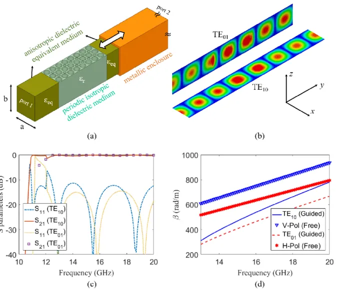
This chapter is concerned with a complete analysis of special types of integrated waveguides. Those waveguides are the building blocks of the main ideas of this thesis which are the polarization selective coupling (PSC) and the effective polarization independent coupling (EPIC). This is for the purpose of the dual-polarization handling within planar integrated circuits.
The proposed idea about separating or combining the two orthogonal signals using the selective coupling mechanism simplifies the analysis and design as introduced through the thesis. This is achieved by designing only one coupler which acts differently for different polarization. This simplifies the geometry when compared to other OMT structures which depends on two separate couplers oriented on different planes such as that discussed in [34]. This also relatively reduces the structure size compared to other OMT designs. For example, the dielectric-based design in [35] has a physical size of 30 20.9 20.7 mm 3 when operating around 30 GHz with a bandwidth of 150 MHz, but the proposed dielectric-filled PSC-based OMT has a physical size of
3
45 18 3 mm when working around 38 GHz with a bandwidth of 5 GHz. For the air-filled designs, the structure in [14] has a physical size of 34 52 68 mm 3, without the antenna, when operating around 32 GHz with a bandwidth of 42% while the proposed air-filled PSC-based OMT including the horn antenna has a physical size of 23 42 69 mm 3when operating around 32 GHz with a bandwidth of 23%. From these straightforward comparisons, the proposed OMT structure shows an interesting reduction in profile. Moreover, the design in [36] showed an interesting compact OMT, but it cannot be integrated within dielectric substrates in the printed circuit board (PCB) designs while the proposed OMT with its reduced planar profile (without the metal enclosure designed only for measurement) in this work shows a great possibility for integration with PCB and other processes-based planar structure enabled applications. However, the proposed OMT has a relatively limited bandwidth governed by the appearance of modes necessary for coupling as explained later in the next chapter.
Complete analysis and design of the previously mentioned couplers, and accordingly OMTs, are considered in this thesis based on nonradiative dielectric (NRD) guide [37] and SIW [38]
technologies. By means of those technologies, a compact OMT with planar profile is designed based on theoretical analysis and experimental observation.
2.1 SIW guiding structures for polarization diversity
The building blocks of microwave circuits and components are transmission lines and waveguides. Historically, with every new type of RF transmission line, there is an associated spin-off in the wireless industry. Depending on the physical structure and energy guiding mechanism, each type of RF transmission line becomes more suitable in one frequency range than the other. For example, microstrip lines are efficient only up to few GHz while rectangular waveguides, RWG, are more effective and practical in size in the range of few tens of GHz.
Another very effective transmission line, is the Substrate Integrated Waveguide, SIW, which bridged this gap between microstrip lines and RWG, enabling the integration of the two technologies [39].
Conventionally, in SIW the dominant mode of operation is the regular RWG TE10 mode. The bandwidth of single-mode operation is always determined by the cutoff frequency of the second higher order mode. It is conventionally guaranteed that the second higher order mode is the TE20 given that the cross-section dimensions satisfy the inequality a>2b, where a and b are the cross sectional dimensions of the SIW as shown in the inset of Figure 2.1. One can observe that in the mm-wave band, and given the typical thickness of widely used microwave substrates, the design inequality mentioned above can hardly be satisfied.
To validate this idea, consider the design process of the SIW shown in Figure 2.1. A designer would first decide on the dielectric substrate to use. The commercially available materials would have the relative permittivity r ranging from about 2.2 to 10.2 with typical thickness, b, ranging from about
10 to 75 mils. If the SIW is to operate in the mm-wave band, the designer will calculate a according to the typical equation derived from the cutoff frequency of the TE10 mode shown in the top of Figure 2.1.
The designer would then face the problem that the calculated value, a, will be in the range of b and the second higher order mode will no longer be the TE20 mode, but would rather be the orthogonally polarized TE01 mode. The condition is even worse taking into consideration the anisotropy of the typical dielectric substrate, where the effective permittivity seen by the horizontally polarized TE01
11
Figure 2.1. Cross-comparison of SIW cross-sectional dimensions in the mmW range.
mode is higher than that seen by the vertical field of the TE10 mode. Electrically, this makes b even larger than the values shown in Figure 2.1.
Thinking of the horizontally polarized TE01 mode in an SIW structure raises interesting research questions. The periodic wall is suitable only for guiding the vertical TE10 mode, so how to guide the horizontal mode to utilize it efficiently rather than trying to suppress it? Is it going to radiate and leak into the substrate? Dielectric slab waveguides are well known in optics and well utilized to build useful components and enabling technologies, is it useful to utilize them in the mmW band? The main idea in this chapter is to study the combination of the dielectric slab guiding mechanism and the conventional SIW in one physical structure.
The following sections study this combination deeply starting from a comprehensive analysis of the SINRD waveguides.
2.2 NRD guiding structures and its image form
The SIW structure presented in the previous section is one of the most efficient guiding structures due to its simple implementation and integration in RF and mmW circuits [40]. Another sort of integrated waveguides is the substrate integrated nonradiative dielectric (SINRD) waveguide [41-43]. The SINRD waveguide does not compete with the SIW structures due to its long-perceived-complicated analysis, bulkiness and the difficulty to achieve single mode operation. This chapter attempts to clarify the analysis of the NRD guides in a way that facilitates the most effective use of such guides.
SINRD waveguide is an integrated form of the well-known dielectric slab waveguide [44]. In such waveguides, the wave guidance occurs due to a step in the value of permittivity of the dielectric material constituting the waveguide; with lower permittivity on the bilateral sides than that of the main central guide. In the SINRD waveguide, the permittivity of the sides can be decreased by perforating air-holes in the same material composing the substrate or other means as long as there is a contrast of dielectric constant along the transverse direction according to SINRD design rules. In accordance with that, SINRD technology does not require metal plating inside the air-holes as the substrate integrated waveguides (SIW) [38, 40]. This fact proposes a promising loss, low-cost and high-performance guiding technology for mmW applications [37, 42, 45].
This interesting technology with the previously mentioned advantages has been used in constructing various designs for integrated circuits applications and antennas. For example, the NRD technology showed a great performance and mechanical improvements for designing abridged coupler for mmW applications [46]. The same concept was used for implementing a cruciform coupler as well [47]. This is in addition to the capability of implementing leaky wave antennas based on NRD technology [48, 49].
Integrating such SINRD waveguides with planar circuits is highly sensitive to the required maximum operating frequency [50]. This frequency is related to the effective permittivity of the periodic part of the SINRD waveguide. This is in addition to the need for the exact effective parameter values of the NRD periodic part in order to get the dispersion characteristics for such waveguides. This is required to get more precise designing procedures based on the selected mode of operation. Therefore, the analysis of the NRD periodic part is essential for any application based
13 on this technology. This analysis is required to extract the effective parameters for all electric field orientations.
In previous work, this effective permittivity is mainly calculated based on huge computationally intensive numerical methods such as the finite difference time domain (FDTD) technique [42, 51] or the volume integral equation (VIE) analysis [52, 53]. Those methods showed proper results, but with a complicated procedure and expensive computation. On the other hand, approximate empirical formulations for the effective permittivity of the periodic part were given in [54], but those empirical formulations might lead to inaccurate estimations for the design parameters and accordingly imprecise results.
Moreover, the need for polarization diversity in enhancing the microwave component efficiency [2, 55, 56] makes it essential to yield an accurate analysis for different polarizations of the electric field components. Unfortunately, most of the existing analysis methodologies for the SINRD concerns only single polarization [51, 57]. Based on this, an extensive analytical study for the SINRD waveguide towards various polarizations is needed for accurate calculation of its effective parameters which might lead to more precise designs of dually-polarized microwave components [19, 58, 59].
In this chapter, an exact analytical procedure is introduced for modelling the periodic part of the SINRD waveguide based on eigenmode analysis [60]. This procedure determines the dispersion characteristics of the periodic medium in different directions when it is enclosed between two horizontal metallic plates. The interesting result is that the periodic medium acts as an anisotropic material with different effective permittivity depending on the electric field direction with respect to the periodic air-holes, which has never been reported before in connection with the NRD technology.
The proposed method is validated through many examples and compared with the simulation results where excellent agreement is achieved, and valuable observations are recorded for the interested designers. For example, a specific perforation for the air-holes might lead to converting the anisotropic substrate to isotropic one. Furthermore, the guidance by the periodic part shows three regimes of operation for each specific mode depending on the variation of its effective permittivity with frequency.
Figure 2.2. Physical structure of a two-dimensional periodic medium and its unit cell.
2.2.1 Modelling Effective Anisotropy of SINRD Waveguide
In this section, the extraction of effective parameters of the periodic medium is developed based on an eigenmode analysis. Then, this method is validated through the eigenmode solver of the HFSS simulation tools. After that, a setup for a possible validation is introduced using a rectangular waveguide filled with the perforated medium and its effectively equivalent medium together in a cascade that is constructed specifically for the presented problem. It is also shown that anisotropic material can be converted to isotropic one using this geometrical alteration of the material structure via air-holes. This process, we call isotropization. Later, the application of the presented technique is utilized in designing an SINRD waveguide supported with detailed explanations for the regimes of operation.
15 2.2.1.1 Extraction of effective permittivity tensor
Any SINRD waveguide consists of three regions, the main guide in the center and two periodic parts surrounding it. Considering the periodic part structure which is shown in Figure 2.2. It consists of a periodic dielectric medium enclosed between two horizontal metallic plates. The unit cell with specified dimensions and parameters is presented in the same figure.
The Helmholtz wave equation for electric field E in such a structure can be easily written as,
2 2 1 , , ; , , ; , x y z x y z x y c E E (2.1) where, E
x y z, , ;
a Eˆxˆxa Eˆy ˆya Eˆz ˆz (2.2) Due to the medium periodicity, the reciprocity of the physical relative permittivity can be expanded as a double Fourier series as,
2 2 1 , u v j x y p p uv u v e x y
(2.3) where the Fourier coefficient uv is given by,
2 2 1 1 , u v j x y p p uv A e dA A x y ∬
(2.4) where A p2 is the cross-sectional area of the unit cell. For the specific case in Figure 2.2, the function uv which is related to the geometrical distribution of the periodic medium can be writtenexplicitly by the help of [61] in the form,
1 2 (G ) 1 2 2 1 2 1 0 1 0 r r J r r p Gr r r p uv p G G (2.5)where r is the air-hole radius and G is defined by,
According to Floquet theorem, the electric field can also be expanded as a periodic function in the
xy-plane with period p where the propagation constants in x- and y-directions are kx and ky,
respectively.
2 2 ˆ , , ; sin co s x y x m n x mn j k x k y p p m n x mn i z E x y z E b D i z e b
(2.7)where the sin and cos functions are used to consider the effect of the two PEC plates enclosing the whole structure. Taking i0 corresponds to uniform field distribution in the z-direction between the two plates. The y-and z-components ˆE and ˆy E of the electric field are expanded in a form z
identical to (2.7).
Taking a Fourier series expansion of (2.1) is achieved simply by substituting (2.7) and (2.3) in (2.1) , where multiplication on the left-hand side is converted to a spatial convolutional sum expressed by three coupled equations for the field components in the different directions shown below,
2 2 2 , 2 2 2 2 2 y x mn N N u m v n x y y mn x uv N N x z mn n i k E p b m n k k E E p p c m i k E p b