HAL Id: hal-00938352
https://hal.archives-ouvertes.fr/hal-00938352
Submitted on 29 Jan 2014
HAL is a multi-disciplinary open access
archive for the deposit and dissemination of
sci-entific research documents, whether they are
pub-lished or not. The documents may come from
teaching and research institutions in France or
abroad, or from public or private research centers.
L’archive ouverte pluridisciplinaire HAL, est
destinée au dépôt et à la diffusion de documents
scientifiques de niveau recherche, publiés ou non,
émanant des établissements d’enseignement et de
recherche français ou étrangers, des laboratoires
publics ou privés.
Carbon nanotube-metal-oxide nanocomposites:
microstructure, electrical conductivity and mechanical
properties
Emmanuel Flahaut, Alain Peigney, Christophe Laurent, Ch. Marlière,
Françoise Chastel, Abel Rousset
To cite this version:
Emmanuel Flahaut, Alain Peigney, Christophe Laurent, Ch. Marlière, Françoise Chastel, et al..
Carbon nanotube-metal-oxide nanocomposites: microstructure, electrical conductivity and mechanical
properties. Acta Materialia, Elsevier, 2000, vol. 48, pp. 3803-3812. �10.1016/S1359-6454(00)00147-6�.
�hal-00938352�
O
pen
A
rchive
T
OULOUSE
A
rchive
O
uverte (
OATAO
)
OATAO is an open access repository that collects the work of Toulouse researchers and
makes it freely available over the web where possible.
This is an author-deposited version published in :
http://oatao.univ-toulouse.fr/
Eprints ID : 10686
To link to this article :
DOI:10.1016/S1359-6454(00)00147-6
URL :
http://dx.doi.org/10.1016/S1359-6454(00)00147-6
To cite this version :
Flahaut, Emmanuel and Peigney, Alain and Laurent, Christophe and
Marlière, Ch. and Chastel, Françoise and Rousset, Abel Carbon
nanotube–metal–oxide nanocomposites: microstructure, electrical
conductivity and mechanical properties. (2000) Acta Materialia, vol.
48 (n° 14). pp. 3803-3812. ISSN 1359-6454
Any correspondance concerning this service should be sent to the repository
administrator:
[email protected]
CARBON NANOTUBE–METAL–OXIDE NANOCOMPOSITES:
MICROSTRUCTURE, ELECTRICAL CONDUCTIVITY AND
MECHANICAL PROPERTIES
E. FLAHAUT1, A. PEIGNEY1†*, Ch. LAURENT1, Ch. MARLIE` RE2, F. CHASTEL1and
A. ROUSSET1
1CIRIMAT, UMR CNRS 5085/ LCMI, Centre Inter-universitaire de Recherche et d’Inge´nierie des
Mate´riaux, Universite´ Paul-Sabatier, F 31062 Toulouse, cedex 4, France,2Laboratoire des Verres, UMR
CNRS 5587, Universite´ Montpellier 2, C.C. 69, place Euge`ne Bataillon, F 34095 Montpellier, cedex 5, France
Abstract—Carbon nanotube–metal–oxide composites (metal=Fe, Co or Fe/Co alloy; oxide=Al2O3, MgO or
MgAl2O4) have been prepared by hot-pressing the corresponding composite powders, in which the carbon
nanotubes, mostly single or double-walled, are very homogeneously dispersed between the metal–oxide grains. For the sake of comparison, ceramic and metal–oxide nanocomposites have also been prepared. The microstructure of the specimens has been studied and discussed in relation to the nature of the matrix, the electrical conductivity, the fracture strength and the fracture toughness. The carbon nanotube–metal–oxide composites are electrical conductors owing to the percolation of the carbon nanotubes. 2000 Acta Metallurgica Inc. Published by Elsevier Science Ltd. All rights reserved.
Re´sume´—Des composites nanotube de carbone–me´tal–oxyde (me´tal=Fe, Co ou alliage Fe/Co; oxyde=Al2O3,
MgO ou MgAl2O4) ont e´te´ pre´pare´s par frittage sous charge des poudres composites correspondantes, dans
lesquelles les nanotubes de carbone, essentiellement mono- ou bi-feuillets, sont disperse´s de fac¸on tre`s homo-ge`ne entre les grains me´tal–oxyde. Des ce´ramiques et des nanocomposites me´tal–oxyde ont aussi e´te´ pre´pare´s pour permettre des comparaisons. La microstructure des e´chantillons a e´te´ e´tudie´e et discute´e en relation avec la nature de la matrice, la conductivite´ e´lectrique, la re´sistance a` la rupture et la te´nacite´. Les composites nanotube de carbone–me´tal–oxyde sont conducteurs e´lectriques graˆce a` la percolation des nanotubes de car-bone.
Keywords: Hot pressing; Scanning electron microscopy (SEM); Composites; Electrical properties; Mechan-ical properties
1. INTRODUCTION
Amongst the works actually devoted to the possible applications of carbon nanotubes (CNTs), their incor-poration in a polymer [1–12], metal [13, 14], or cer-amic [15–18] matrix and the characterization of the microstructure and properties of these dense com-posite materials are investigated. Indeed, it is pro-posed that owing to their remarkable mechanical properties [19–21], the CNTs could advantageously substituted for carbon fibers as reinforcing elements in composites. Other important particularities of CNTs are their very high aspect ratio and their met-allic or semiconducting character [22, 23]. Thus, their addition to a polymer matrix leads to a very low
elec-* E-mail address: [email protected] (A. Peigney) † To whom all correspondence should be addressed. Tel.:
+33-61-55-62-80; fax:+33-61-55-61-63.
trical percolation threshold [3] and allows one to obtain, with only very small amounts of CNTs, an electrical conductivity sufficient to provide an electro-static discharge [7].
CNT–SiC composites have been prepared by Ma et
al. [15], who mixed large multiwall carbon nanotubes
(MWNTs: 30–40 nm in diameter) with SiC powder and hot-pressed the mixture. These authors reported an improvement of about 10% over monolithic SiC both in bending strength and fracture toughness, but the microstructure of the dense materials was not fully investigated. Therefore, the contribution of the CNTs to the mechanical properties was not clearly established in this work. The present authors have reported a novel catalytic route for the in situ forma-tion, in a composite powder based on alumina, of
sin-gle-wall carbon nanotubes (SWNTs) and thin
MWNTs [16, 24]. The microstructure and mechanical
pre-pared by hot-pressing the nanocomposite powders have been investigated [17, 18]. In comparison to similar carbon-free nanocomposites, the relative den-sities are lower, the matrix grains are smaller and the fracture strength and fracture toughness are generally markedly lower. Nevertheless, SEM observations of composite fractures indicated that the CNT bundles, which are very flexible, locally act to dissipate some of the fracture energy. Amongst the reasons which could explain the lack of mechanical reinforcement at the macroscopic scale, we reported the too-low vol-ume fraction of CNTs and the presence of others species, notably large diameter (>15 nm) filamentous carbon that we call nanofibres. It was also pointed out that the influence of the nature of the ceramic matrix in which the CNTs are dispersed was to be investi-gated.
Working on the powder synthesis, the present authors have greatly enhanced both the quantity of
CNTs and the quality of carbon (much less
nanofibers) in the CNT–Fe–Al2O3powders [25, 26].
Furthermore, novel composite powders, CNT–Fe/Co–
MgAl2O4and CNT–Co–MgO, have been synthesized
[27–30]. The aims of this work are to prepare dense
CNT–Fe–Al2O3 composites containing higher
quan-tities of CNTs and much less nanofibers than those previously investigated [17, 18] and novel dense
CNT–Fe/Co–MgAl2O4 and CNT–Co–MgO
com-posites. For the sake of comparison, ceramics
(MgAl2O4and MgO) and composites without CNTs
(Fe/Co–MgAl2O4 and Co–MgO) are also prepared.
The microstructure and mechanical properties of these dense materials are investigated. The electrical conductivity at room temperature is also measured, correlated to the apparent quantity of CNTs and com-pared with values obtained by other authors for CNT– polymer composites.
2. EXPERIMENTAL
The preparation of oxide solid solution and CNT– metal–oxide composite powders was described in
pre-vious papers [24–29]. By heating up to 1000°C in a
H2–CH4 atmosphere, monophased oxide solid
sol-utions are submitted to a selective reduction which leads to the formation of transition metal particles, a few nanometers in diameter, both inside and at the surface of each grain of the powder. When they reach the required size, the surface metal particles catalyze the in situ formation of SWNTs and thin MWNTs which gather in extensively branched bundles and are extremely well dispersed as a web-like network between the matrix agglomerates (Fig. 1a–f). In addition, some carbon is also found in the form of graphene layers wrapping the metal particles which have not catalyzed the formation of CNTs. Statistical studies on HREM images of individual CNTs have shown than over 80% have only one or two walls, and that most diameters are smaller than 6 nm [26, 30]. Carbon-free metal–oxide powders are similarly
prepared by heating up to 1000°C in a H2atmosphere.
For the sake of brevity, the powders are labeled
CMA1, CMA2 (CNT–Fe–Al2O3), B, MB and CMB
(MgO, Co–MgO and CNT–Co–MgO, respectively)
and D, MD and CMD (MgAl2O4, Co–MgAl2O4and
CNT–Co–MgAl2O4, respectively). Note that
attrition-milling was conducted on the D powder and on the oxide solid solutions used as precursors for the CMA2, MD and CMD composite powders. This attrition-milling leads to a contamination of the
corre-sponding powders by some ZrO2 particles, about 1
µm in size.
The powders were uniaxially hot-pressed at 43
MPa in graphite dies, in a primary vacuum, at 1500°C
(MgAl2O4 ceramic, Al2O3– and MgAl2O4–matrix
composites) or 1600°C (MgO ceramic and MgO–
matrix composites) with a dwell time fixed at 15 min. The dense specimens (20 mm in diameter and 2 mm thick) for mechanical tests were ground with diamond suspensions. Surfaces were polished to an optical fin-ish and thermal and/or chemical etching treatments were adjusted to reveal the grain boundaries.
Starting powders, polished surfaces, etched sur-faces and fracture profiles of dense specimens were observed by scanning electron microscopy (SEM).
The average grain size of the oxide (Gm) was
determ-ined by the linear intercept method [31]. The maximal size of the metal and ZrO2particles (dmetaland dZrO2,
respectively) were measured on back-scattered elec-tron images of polished specimens. Relative densities (d%) were calculated from measurements obtained by the Archimedes method, using the density of graphite (dgraphite=2.25 g/cm
3) for CNTs. The powders and the
hot-pressed materials were also studied by X-ray dif-fraction (XRD).
The transverse fracture strength (sf) was
determ-ined by the three-point-bending test on parallel-epipedic specimens (1.6×1.6×18 mm3) machined with
a diamond blade. The fracture toughness (KIc) was
measured by the SENB method on similar specimens notched using a diamond blade 0.3 mm in width. The calibration factor proposed by Brown and Srawley [32] was used to calculate the SENB toughness from the experimental results. Cross-head speed was fixed
at 0.1 mm/min. The values given forsfand KIc are
the average of measures on seven and six specimens, respectively. The electrical conductivity of dense specimens was measured at room temperature with
d.c. currents on parallelepipedic specimens
(1.6×1.6×8 mm3), parallel to their length, i.e.
perpen-dicular to the hot-pressing axis. The current densities
used were lower than 160 mA/cm2.
3. RESULTS AND DISCUSSION 3.1. Powder characterization
It is first important to note that the metal content has been chosen in order to optimize both the quality of carbon and the quantity of CNTs in the different
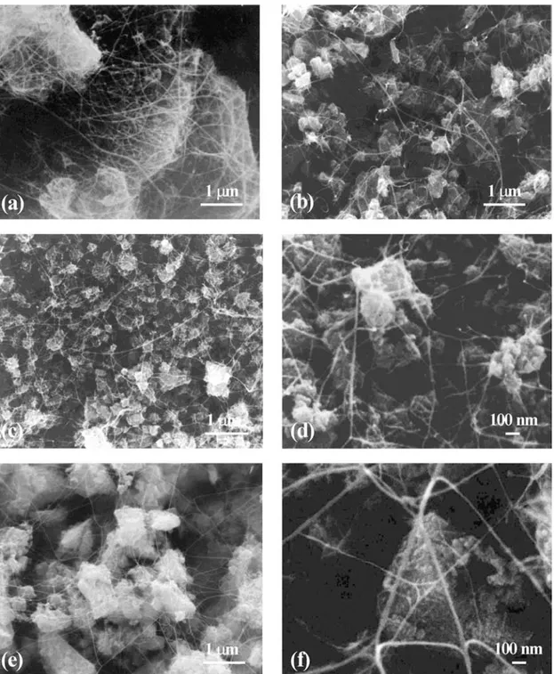
Fig. 1. SEM images of CNT–metal–oxide nanocomposite powders: (a) CNT–Fe–Al2O3(CMA1); (b) CNT– Fe–Al2O3(CMA2); (c, d) CNT–Co–MgO (CMB); (e, f) CNT–Fe/Co–MgAl2O4(CMD).
powders. Thus, depending on the nature of the matrix, a specific metal content was used (Table 1). The XRD patterns (not shown) of the composite powders reveal
the peaks ofa-Fe, e-Co or cubic-Fe/Co alloy besides
those of the involved matrix, a-Al2O3, MgO or
MgAl2O4, respectively. For CMA1 and CMA2,
cementite Fe3C is also detected. In powders CMA2,
D, MD and CMD, which derive from attrition-milled
oxides, some of the different forms of ZrO2(cubic,
tetragonal and/or monoclinic) are detected, showing
some contamination from the ZrO2balls, which is of
the order of a few wt%.
Macroscopic parameters related to the presence of carbon are reported in Table 1. The carbon content
(Cn) is slightly lower for CMA1 (4.8 wt%) than for
CMA2 (5.7 wt%), probably owing to the presence of more catalytic particles on the matrix grain surfaces for the latter powder. Indeed, CMA1 and CMA2 pow-ders were prepared from the same oxide solid sol-ution, except that it was attrition-milled prior to
Table 1. Some characteristics of the metal–oxide and carbon nanotube–metal–oxide nanocomposite powders
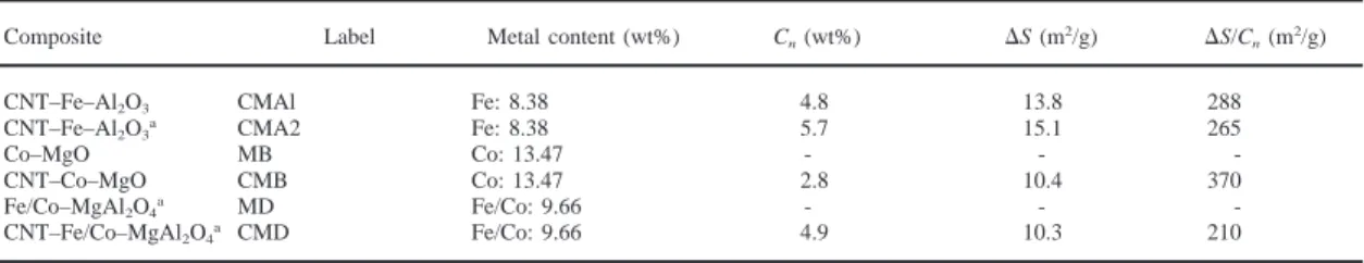
Composite Label Metal content (wt%) Cn(wt%) ⌬S (m2/g) ⌬S/Cn(m2/g)
CNT–Fe–Al2O3 CMAl Fe: 8.38 4.8 13.8 288
CNT–Fe–Al2O3a CMA2 Fe: 8.38 5.7 15.1 265
Co–MgO MB Co: 13.47 - -
-CNT–Co–MgO CMB Co: 13.47 2.8 10.4 370 Fe/Co–MgAl2O4a MD Fe/Co: 9.66 - -
-CNT–Fe/Co–MgAl2O4a CMD Fe/Co: 9.66 4.9 10.3 210
Cn: carbon content;⌬S: surface area of carbon in 1 g of composite powder, representing the quantity of nanotubes; ⌬S/Cn: specific surface area
of carbon, representing the quality of nanotubes.
aSpecimens prepared from powders attrition-milled before reduction. Note that for CNT-containing composites, the carbon content was not taken
into account in the calculation of the metal content.
reduction for CMA2, resulting in a finer agglomerate
size. The carbon content for CMD (Cn=4.9 wt%) is
similar to that measured for CMA1, but it is notably
lower in the case of CMB (Cn=2.8 wt%). As proposed
elsewhere [25, 26], the surface area of carbon found
in 1 g of composite powder (⌬S — Table 1) is a good
representation of the quantity of CNTs in the powder.
⌬S is about 1.5 times higher in Al2O3–matrix
com-posites than in MgO– and MgAl2O4–matrix
com-posites. From Cnand⌬S, one obtains the specific
sur-face area of the carbon (⌬S/Cn — Table 1) which
represents what we call the quality of carbon in the
powder. A higher figure for⌬S/Cndenotes more
car-bon in the form of CNTs, or CNTs with a smaller diameter and/or less walls, or bundles of CNTs with smaller diameter, i.e. made up of less CNTs [25,26,33]. The CMB powder presents the higher
quality of carbon (⌬S/Cn=370 m2/g) whereas the
CMD powder presents the lower one (⌬S/Cn=210
m2/g).
SEM images of the powders containing CNTs are reported in Fig. 1. The web-like network of CNT bundles is clearly observed for all powders. As men-tioned above, the matrix agglomerates are much
larger for CMA1 (>10µm — Fig. 1a) than for CMA2
(⬍1 µm — Fig. 1b). The matrix agglomerates for
CMB (Fig. 1c, d) are only of a few hundreds of nano-meters in size. The CNT bundles in this powder are very thin. In the CMD powder (Fig. 1e, f), some
matrix agglomerates are almost 2µm in size and the
CNT bundles are larger than in CMB (Fig. 1d). These observations are in agreement with the values of
⌬S/Cnreported above.
3.2. Microstructure of the hot-pressed specimens
Comparing with the XRD patterns recorded on the powders, the XRD patterns of the hot-pressed com-posites show only a few minor differences. Firstly, dense CMA1 and CMA2 contain more cementite than the corresponding powders. At a high temperature, the larger Fe surface particles probably react with the
graphene layers which generally cover them
[16,17,25,29] and some CNTs may also react with the Fe particles. This phenomenon is more clearly marked in CMA2 because the powder contains more Fe surface particles owing to the attrition-milling of
its precursor oxide powder. Traces of cementite are also detected in CMD. Secondly, in CNT-containing composites, a wide peak corresponding to the
dis-tance between graphene layers (d002=0.34 nm)
appears, which reflects a higher crystallization level of the graphenic species than in the powders. Finally, in all dense composites, the width of the metal peaks decreases, compared to the powders, reflecting the growth of the intergranular metal particles upon hot-pressing. However, this phenomenon is less marked in CNT–metal–oxide composites, probably because it is inhibited by the presence of graphene layers cover-ing most metal particles in the powders, as well as by the carburization in the case of Fe particles.
All the CNT-containing composites present
unachieved densifications, with relative densities (d — Table 2) 5–8% below those of the correspond-ing carbon-free metal–oxide composites. The MgO ceramic also presents a fairly poor relative density. Some microstructural characteristics were determined from SEM observations of etched and unetched pol-ished surfaces (Table 2). In the case of Al2O3– and
MgAl2O4–matrix composites, the matrix grain size
(Gm) is very small (0.3–0.8 µm) and the metal
par-ticles size (dmetal) is not higher than 0.5µm. Both Gm
and dmetalare higher for MgO–matrix composites (3–
7µm and 1.5–2µm, respectively). Note that previous
works [34] on carbon-free metal–oxide
nanocompos-ites have shown that the metal nanoparticles (⬍10
nm) located within the matrix grains in the powder remain in intragranular position in the dense material and therefore are protected against excessive growth upon hot-pressing. Thus, the metal–oxide and CNT–
metal–oxide specimens are hybrid
micro/nanocomposites [35] containing both
micrometer-sized metal particles which are at inter-granular positions and nanometer-sized intrainter-granular metal particles.
The comparison of the matrix grain size for the
MgAl2O4 ceramic (Gm=13.0 µm) and for the
MgAl2O4–matrix composites (Gm=0.5–0.8µm) shows
that the matrix grain growth during hot-pressing is
hampered by the metal particles (inter- and
intragranular) and by the CNTs. Moreover, the spe-cific role of the CNTs in the inhibition of matrix grain growth is confirmed by the average matrix grain size
Table 2. Relative density and microstructural characteristics of the hot-pressed ceramics and nanocomposites
Ceramic or composite Label d (%) Gm(µm) dmetal(µm) dZrO2(µm)
CNT–Fe–Al2O3 CMAl 88.7 0.3 ⱕ0.5 -CNT–Fe–Al2O3a CMA2 87.5 0.3 ⱕ0.5 ⱕ1 MgO B 90.1 5 - -Co–MgO MB 96.6 7 ⱕ2 -CNT–Co–MgO CMB 92.9 3 ⱕ1.5 -MgAl2O4a D 99.7 13 - ⱕ1 Fe/Co–MgAl2O4a MD 98.2 0.8 ⱕ0.5 ⱕ1 CNT–Fe/Co–MgAl2O4a CMD 90.6 0.5 ⱕ0.5 ⱕ1
d: relative density calculated by assuming that all carbon has the density of graphite, with dgraphite=2.25 g/cm3; Gm: average grain size of the
oxide; dmetal: diameter of the larger metal particles; dZrO2: diameter of the larger ZrO2particles in specimens prepared from powders attrition-milled
before reduction (a).
in CMA1 and CMA2 (Gm=0.3µm), which is much
smaller than that (ca. 2 µm) reported for Fe–Al2O3
nanocomposites [34]. This is in agreement with our previous results [17, 18]. However, this effect of CNTs is markedly lower in the CMB composites (Table 2), probably because, as will be shown here-after, most CNTs are destroyed during hot-pressing. Furthermore, SEM observations also reveal that the
ZrO2 particles present as a contamination in the
CMA2, D, MD and CMD powders are found as slightly submicronic particles in the hot-pressed materials. In addition, it is observed that the CNT-containing composites present pores which are gener-ally larger than the matrix grains and are sometimes elongated. This is a consequence of the presence of agglomerates in the powders, which are only partially crushed during hot-pressing.
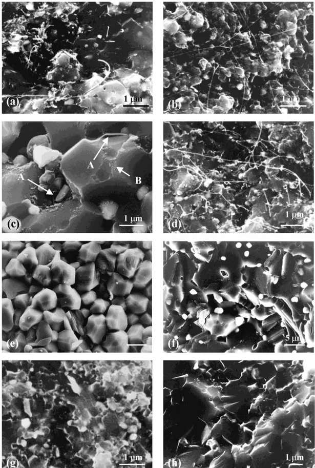
The SEM observations of the fracture surface of CNT–metal–oxide composites (Fig. 2a–d) show the presence of CNT bundles in the materials but in very different quantities from one sample to another. For CMA1 (Fig. 2a), a few long CNT bundles emerge from the fracture surface but most seem to be cut near the surface, perhaps after some pull-out. More very long CNT bundles appear for CMA2 (Fig. 2b), and much more for CMD (Fig. 2d). On the contrary, it is very difficult to observe even a few CNTs on the sur-face fracture of CMB (A in Fig. 2c). However, some deposits probably composed of carbon are also observed (B in Fig. 2c). Thus, it clearly appears that many CNT bundles remain in CMA1, CMA2 and CMD, whereas most of the CNTs have been destroyed during the hot-pressing of CMB. This could be a consequence either of a specific chemical inter-action between the CNTs and the MgO matrix or of the higher hot-pressing temperature used for the
MgO-based specimens (1600°C vs 1500°C for the
other materials), owing to the difficulty in densifying them. A high temperature chemical interaction between the CNTs and the residual gas in the furnace is also a possibility. We also hot-pressed a CNT–Co–
MgO composite at a lower temperature (1200°C). The
densification of the material was very low (82%) but the quantity of CNT bundles was similar or higher than that observed for CMA2 or CMD (Fig. 2b, d).
The presence of carbon deposits (B in Fig. 2c) points towards a thermal instability of CNTs in the primary
vacuum at 1600°C rather than towards a chemical
reaction with MgO.
For Al2O3– and MgAl2O4–matrix materials, a
com-parison on SEM images of the quantities of CNTs between the powders and dense specimen is difficult, because in the powders many superimposed CNTs appear on a depth of several micrometers (three dimensions), whereas for the hot-pressed specimen, only the CNTs at the fracture surface are observed (two dimensions). This can lead to an underestimation of the CNTs quantity in the latter case. However, it seems that the quantity of CNTs is significantly decreased during the hot-pressing, particularly for Al2O3-based composites.
3.3. Electrical conductivity
The electrical conductivity (s — Table 3) of all
CNT-containing composites is in the range 0.2–4.0
S cm⫺1whereas the ceramics and the metal–ceramic
composites are insulating (s⬍10⫺9 S cm⫺1).
More-over, from one specimen to another, the values are fairly well correlated to the quantity of CNTs observed on the fracture surfaces (Fig. 2a–d). Indeed, the lower value is obtained for CMB in which the majority of CNTs seems to have been destroyed (Fig. 2c). Both CMA2 and CMD composites have been prepared from very fine powders, thus leading to a better dispersion of the CNT bundles within the matrix (Fig. 1b, c) compared to CMA1 for which the matrix agglomerates are much larger. This probably leads to a better connectivity of the CNTs in CMA2 and CMD dense composites than in CMA1, account-ing for the higher electrical conductivity of the former
materials (1.5–4.0 vs 0.4–0.8 S cm⫺1). Furthermore,
the values are significantly higher for CMA2 than for
CMD because the quantity parameter (⌬S — Table
1) is 50% higher for CMA2 than for CMD. To assess the real role of the CNTs in the electrical conductivity of CMB, the MgO matrix was dissolved by a mild HCl treatment known to not damage the CNTs [30] and the so-obtained carbon species were observed by high resolution electron microscopy. In agreement with SEM observations (Fig. 2c), only a
Fig. 2. SEM images of the fracture surface of ceramics and nanocomposites: (a) CNT–Fe–Al2O3(CMA1); (b) CNT–Fe–Al2O3(CMA2); (c) CNT–Co–MgO (CMB); (d) CNT–Fe/Co–MgAl2O4(CMD); (e) MgO (B); (f)
Table 3. Electrical conductivity (s), fracture strength (sf), fracture toughness (KIc) and fracture mode of the hot-pressed ceramics and nanocomposites
Ceramic or composite Label or reference s (S cm⫺1) s
f(MPa) KIc(MPa m1/2) Fracture mode
Al2O3 [34] - 335 4.4 Intergranular
Fe–Al2O3 [34] - 630 7.2 Mixed
CNT–Fe–Al2O3 [17] - 540 3.6 Mixed
CNT–Fe–Al2O3* [18] - 295 2.7 Intergranular
CNT–Fe–Al2O3 CMAl 0.4–0.8 400 5.0 Mixed
CNT–Fe–Al2O3* CMA2 2.8–4.0 296 3.1 Intergranular
MgO B n.m 202 - Intergranular Co–MgO MB n.m. 283 - Mixed CNT–Co–MgO CMB 0.2 254 - Intergranular MgAl2O4* D n.m. 308 - Transgranular Fe/Co–MgAl2O4* MD n.m. 212 2.94 Mixed CNT–Fe/Co–MgAl2O4* CMD 1.5–1.8 221 1.71 Mixed
aSpecimens prepared from powders attrition-milled before reduction; n.m.: not measurable; mixed: the fracture presents both the inter- and
transgranular characters.
small proportion of undamaged CNTs were observed, the majority of carbon being found in the form of disorganized graphene layers, which probably reflects
a damage to the CNTs during hot-pressing at 1600°C.
Moreover, similar experiments have been conducted
on a composite hot-pressed at 1700°C and have
revealed the transformation of all the CNTs into dis-organized graphene layers. This material had a very
low electrical conductivity (s⬍10⫺8S cm⫺1). These
results show that, for the three categories of CNT– metal–oxide composites, including CMB in which the quantity of CNTs seems to be very low, the electrical conductivity can be attributed to a percolation phenomenon between CNT bundles. The very high aspect ratio of the CNT bundles (>104) makes the
per-colation possible with a very small content of CNTs. Similarly, Sandler et al. reported, for MWNTs–poly-mer composites, an electrical conductivity equal to
10⫺2S cm⫺1with only 0.1 vol% of MWNTs [3] and
Yoshino et al. measured 0.05–0.30 S cm⫺1with 10
and 20 vol% of MWNTs, respectively [7]. We have estimated that in the present starting powders, the CNTs volume fraction could be up to about 20 vol% but it seems to be much lower in the dense materials (perhaps only a few vol% and even less in CMB), owing to damages during hot-pressing. In the present experiments, most CNTs have only one or two walls and are less than 6 nm in diameter, which is favorable to an enhanced conductivity, at identical volume frac-tions, in comparison with large MWNTs. Thus, we infer that the difference in the characteristics of the CNTs explains why we obtain a higher electrical con-ductivity than previously reported [3, 7]. Some differ-ences in the CNTs structure and the resulting electri-cal behavior (metallic or semiconductor) could also account for these differences.
3.4. Mechanical properties and fracture surface characteristics
Compared to previously studied CNT–Fe–Al2O3
composites [17, 18], CMA1 and CMA2 differ both by a higher quantity of CNTs in the starting powder and a better quality of carbon (much less nanofibers).
The characteristics of CMA1 (Table 3) can be com-pared with those of the composite reported in Ref. [17], both having been prepared from powders with micrometer-sized agglomerates: the fracture strength of CMA1 is lower but its fracture toughness is higher, which could be correlated to some differences in the microstructure, the densification is lower for CMA1 (88.7% vs 91%) and the matrix grains are smaller (0.3
vs about 1 µm). The higher quantity of CNTs in
CMA1 seems to favor the inhibition of matrix grain growth and to hamper the densification. Conse-quently, more elongated pores subsist in the present
composite, which could explain the lower value ofsf
(Table 3). On the contrary, the increase in the quantity of CNTs in CMA1 may result in an easier transfer of the stress and thus could account for the significant
increase in the fracture toughness (from 3.6 MPa m1/2
for [17] to 5.0 MPa m1/2for CMA1).
It has been shown [34, 35] that the hybridization of microcomposites and nanocomposites could result in a further improvement in both the fracture strength and fracture toughness, which was associated with a mixed inter/trans-granular fracture mode. The fracture strength and fracture toughness of CMA1 are higher than those of the Al2O3ceramic prepared by the same
route [34], but are lower than those of Fe–Al2O3
com-posites [34]. Taking into account that CMA1 is poorly densified (only 88.7% vs about 98% [34]), the mech-anical properties can be considered as not so poor and a possible contribution of the CNTs to the reinforce-ment is not to be ruled out. However, it is not clearly demonstrated.
The characteristics of CMA2 (Table 3) are compa-rable to those of the composite reported in Ref. [18], both having been prepared from powders derived from attrition-milled oxide precursors. Compared to CMA1 and the composite in Ref. [17], it appears that the attrition-milling is detrimental tosfand KIcin the
resulting composites (Table 3). Firstly, less intragran-ular Fe particles are obtained upon reduction in the composite powders because the oxide agglomerates in the precursor powders are submicronic, and thus their proportion is also lower in the dense specimens.
In these nanocomposites, the intragranular nanopart-icles generally induce the transgranular fracture mode, which contributes to the mechanical reinforce-ment [34]. In contrast, for CMA2 and for the com-posite in Ref. [18], the fracture mode is intergranular probably in part because there are too few intragranu-lar Fe nanoparticles. Secondly, in the CMA2 powder the CNT bundles are more intimately dispersed in the matrix than in CMA1 and in the dense CMA2 speci-men, the pores are smaller, less elongated but more numerous than in CMA1. Consequently, it is observed that in CMA2 (Fig. 2b), more CNT bundles are located into the pores and are thus not constrained and damaged during the fracture. In contrast, a higher proportion of CNT bundles are included in the dense parts of CMA1 and SEM observations (Fig. 2a) reveal that these CNTs have been damaged during the frac-ture. Thus if CNTs could contribute to any reinforce-ment in this kind of nanocomposite, they would be efficient only in CMA1. Moreover, the presence in
CMA2 of a small quantity of micrometric ZrO2
par-ticles, which usually reinforce the material, cannot
explain the low values ofsf and KIc for CMA2.
Despite an uncompleted densification (90.1%), the fracture strength measured for the MgO ceramic
(σf=202 MPa — Table 3) is comparable to the values
reported by Rice et al. [36] for non-annealed hot-pressed MgO with a similar average grain size (5
µm). The comparison with MgO–matrix
nanocompo-sites shows an evolution ofsfsimilar to that between
Al2O3 and the Al2O3–matrix composites (Table 3).
Indeed,sfis higher for Co–MgO (MB) than for MgO
(B) but slightly lower for CNT–Co–MgO (CMB) than for MB. Comparing B and MB, the improvement of the densification (96.6% vs 90.1% — Table 2) may be sufficient to explain the increase in sf, but it is
also associated with a transition of the fracture mode from purely intergranular to mixed inter/transgranular (Fig. 2e, f). This may be provoked by the presence of intragranular metal nanoparticles, as in the Al2O3–
matrix nanocomposites [34]. The lower value ofsf
for CMB, compared to MB, associated with the tran-sition to a fully intergranular fracture mode, could be correlated with its lower densification but it may also result from the presence of the disordered graphene sheets derived from damaged CNTs. The possible contribution of non-damaged CNTs to the mechanical properties of these MgO–matrix nanocomposites are to be ruled out.
The fracture strength equal to 308 MPa obtained for the MgAl2O4ceramic (D) is higher than the values
previously reported by other authors [37, 38], prob-ably as a consequence of the high densification of the present specimen (99.7%) but also possibly owing to a beneficial effect of the micrometric tetragonal ZrO2
particles [39], a contamination which occurred during the attrition-milling of the starting oxide powder. The fracture mode in D is clearly transgranular (Fig. 2g) showing that for the present material, the critical grain size related to the change of fracture mode is below
13µm (Table 2). Both MgAl2O4–matrix composites
(MD and CMD) have a lower fracture strength than the ceramic D (Table 3) despite a great refinement of
the matrix grain size (Gm— Table 2). However, their
fracture mode remains partially transgranular (Fig. 2d, h) owing to the metal nanoparticles, a strong pro-portion of which are included inside the matrix grain in these nanocomposites as reported by Que´nard et
al. [40]. The CMD composite, which is very
incom-pletely densified (90.6%), shows a fracture strength similar to that of MD but presents a much lower frac-ture toughness. Indeed, many CNTs appear on the fracture surface of CMD (Fig. 2d) but most emerge from pores, as in CMA1 (Fig. 2b) and do not seem to have been constrained during the fracture. Only a few CNTs, included in the densified parts of the material, have been cut near the fracture surface. Thus, we infer that in CMD, as in CMA2, most CNTs cannot be efficient for an eventual reinforcement of the material.
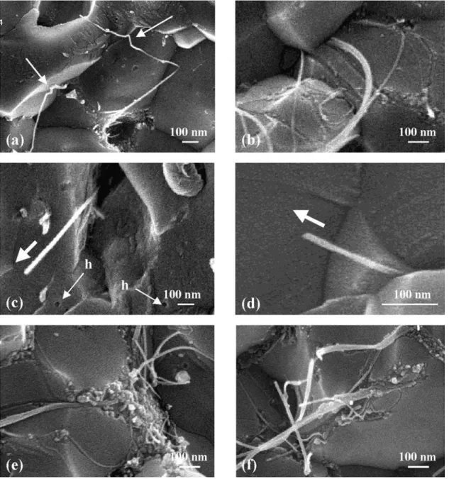
Some observations of the fracture surface of the CMA1 composite were conducted at a higher magni-fication using a field-emission gun scanning electron microscope (SEM-FEG — Fig. 3). Some CNT bundles have been stretched upon hot-pressing, acquiring the shape of the matrix grains at the grain boundary (Fig. 3a). Other CNTs have left their impression at the surface of the matrix grains (Fig. 3b) showing that some wetting of the CNTs by the matrix occurs at the grain boundary during hot-pressing. In a previous paper [17], it was shown that some CNTs embedded in the matrix grain were cut after some pull-out. The same effect also seems to occur with CNT bundles located at matrix grain boundaries in the present composites (Fig. 3c, d). Moreover, small holes can be observed (h in Fig. 3c), which may have been the location of CNTs extracted from a grain. It is well known that, in any fiber-reinforced composite, one of the keys to an efficient reinforcement is that the fiber–matrix interface is not too weak but also not too strong [41], thus allowing some energy absorption under stress by the deco-hesion of these interfaces which often leads to the fiber pull-out.
The SEM observations show: (i) that pull-out
phenomena occur in CNT–Fe–Al2O3composites; (ii)
that CNT bundles may be wetted by the matrix at the grain boundaries; or (iii) have been included inside the matrix grains during hot-pressing. These micro-scopic observations show that some of the CNT bundles, probably weakly bonded to Al2O3, could act
to reinforce the ceramic. However, some CNTs are located in the pores and therefore cannot contribute to the reinforcement of the material. Another important point for achieving a reinforcement is to have a sufficient volume fraction of tubular carbon. This parameter seems to be rather high in the pow-ders: it has been previously estimated to be of the order of 20 vol% [18] and could be higher in the
Fig. 3. SEM-FEG images of the fracture of the CNT–Fe–Al2O3(CMA1) composite showing some aspects of the CNT–matrix interactions.
images of the dense composites (Fig. 2a–d), the vol-ume fractions seem to be much lower and SEM-FEG images furthermore show a lot of carbon deposits at the matrix grain junctions (Fig. 3e, f) arising from the damage of CNTs upon hot-pressing, producing dis-ordered graphene sheets which gather at grain junc-tions.
4. CONCLUSIONS
CNT–Fe–Al2O3composites have been prepared by
hot-pressing composite powders where the quantity of CNTs has greatly been increased in comparison with previous works. Novel dense CNT–Co–MgO
and CNT–FeCo–MgAl2O4composites have also been
prepared. The CNTs, mainly single or double-walled, have grown in situ in the starting powders and thus are very homogeneously dispersed between the metal–oxide grains.
With the Al2O3matrix, the increase of the quantity
of CNTs in the powder leads to a refinement of the microstructure of the hot-pressed specimen but with-out a significant gain in the volume fraction of CNTs. With both the Al2O3and the MgAl2O4matrix, a
frac-tion of the CNTs seems to be destroyed during the
hot-pressing at 1500°C. When using the MgO matrix,
most CNTs are destroyed during a hot-pressing at
1600°C, but the CNTs are not damaged if the
treat-ment is limited to 1200°C. It seems that the quantity of CNTs retained in the massive composite is more
dependant of the treatment temperature than of the nature of the oxide matrix. CNT damaging produces disordered graphene layers which gather at matrix grain junctions.
Probably owing to a too-low relative density (87– 93%), the fracture strength and the fracture toughness of the CNT-containing composites are generally lower than those of the carbon-free metal–oxide com-posites and only marginally higher than those of the ceramics. Microscopical observations show that some CNTs are trapped inside the matrix grains or at grain boundaries and seem to be wetted by the matrix in the case of alumina. Most of these CNTs are cut near the fracture surface after some pull-out and could contribute to a mechanical reinforcement. However, this is not demonstrated at a macroscopic scale. It is necessary in future works to improve the preparation
process to obtain composites with a higher
densification and including a higher volume fraction of CNTs.
Whereas the ceramics and metal–oxide nanocom-posites are insulators, the carbon nanotube–metal– oxide composites are electrical conductors with an
electrical conductivity in the range 0.2–4.0 S cm⫺1
owing to the percolation of the CNTs. The values of the electrical conductivity are fairly well correlated to the relative quantity of CNTs, the specimens becom-ing insulators when the CNTs are destroyed. The so-produced disordered graphene layers do not percolate. For the first time, it has been shown that CNTs confer an electrical conductivity to ceramic–matrix com-posites, which retain the mechanical properties of the ceramic.
Acknowledgements—The authors would like to thank Mr L.
Datas for his assistance in the HREM observations, which have been performed at the Service Commun de Microscopie Elec-tronique a` Transmission, Universite´ Paul-Sabatier.
REFERENCES
1. Ajayan, P. M., Stephan, O., Colliex, C. and Trauth, D.,
Science, 1994, 265, 1212.
2. Shadler, L. S., Giannaris, S. C. and Ajayan, P. M., Appl.
Phys. Lett., 1998, 73, 3842.
3. Yoshino, K., Kajii, H., Araki, H., Sonoda, T., Take, H. and Lee, S., Full. Sci. Technol., 1999, 7, 695.
4. Musa, I., Baxendale, M., Amaratunga, G. A. J. and Eccles-ton, W., Synth. Met., 1999, 102, 1250.
5. Curran, S., Davey, A. P., Coleman, J., Dalton, A., McCar-thy, B., Maier, S., Drury, A., Gray, D., Brennan, M., Ryder, K., Lamy de la Chapelle, M., Journet, C., Bernier, P., Byrne, H. J., Caroll, D., Ajayan, P. M., Lefrant, S. and Blau, W., Synth. Met., 1999, 103, 2559.
6. Bower, C., Rosen, R., Jin, L., Han, J. and Zhou, O., Appl.
Phys. Lett., 1999, 74, 3317.
7. Sandler, J., Shaffer, M. S. P., Prasse, T., Bauhofer, W., Schulte, K. and Windle, A. H., Polymer, 1999, 40, 5967. 8. Lourie, O., Wagner, H. D. and Levin, N., Polymer, 1997,
38, 5699.
9. Wagner, H. D., Lourie, O., Feldman, Y. and Tenne, R.,
Appl. Phys. Lett., 1998, 72, 188.
10. Lourie, O. and Wagner, H. D., Appl. Phys. Lett., 1998,
72, 188.
11. Lourie, O. and Wagner, H. D., Composites Sci. Technol., 1999, 59, 975.
12. Files, B. S., Proceedings of the International Conference
on Integrated Nano/Microtechnology for Space Appli-cations, 1–6 November. Johnson Space Center Houston,
TX, 1998.
13. Kuzumaki, T., Miyazawa, K., Ichinose, H. and Ito, K., J.
Mater. Res., 1998, 13, 2445.
14. Xu, C. L., Wei, B. Q., Ma, R. Z., Liang, J., Ma, X. K. and Wu, D. H., Carbon, 1999, 37, 855.
15. Ma, R. Z., Wu, J., Wei, B. Q., Liang, J. and Wu, D. H.,
J. Mater. Sci., 1998, 33, 5243.
16. Peigney, A., Laurent, Ch., Dumortier, O. and Rousset, A.,
J. Eur. Ceram. Soc., 1998, 18, 1995.
17. Laurent, Ch., Peigney, A., Dumortier, O. and Rousset, A.,
J. Eur. Ceram. Soc., 1998, 18, 2005.
18. Peigney, A., Laurent, Ch., Flahaut, E. and Rousset, A.,
Ceram. Int., 2000, 26, 677.
19. Treacy, M. M. J., Ebbesen, T. W. and Gibson, J. M.,
Nat-ure, 1996, 381, 678.
20. Ruoff, R. S. and Lorents, D. C., Carbon, 1995, 33, 925. 21. Salvetat, J. P., Briggs, G. A. D., Bonard, J. M., Bacsa, R.
R., Kulik, A. J., Stockli, T., Burnham, N. A. and Forro, L., Phys. Rev. Lett., 1999, 82, 944.
22. Dai, H., Wong, E. W. and Lieber, C. M., Science, 1996,
272, 523.
23. Ebbesen, T. W., Lezec, H. J., Hiura, H., Benett, J. W., Ghaemi, H. F. and Thio, T., Nature, 1996, 382, 54. 24. Peigney, A., Laurent, Ch., Dobigeon, F. and Rousset, A.,
J. Mater. Res., 1997, 12, 613.
25. Peigney, A., Laurent, Ch. and Rousset, A., J. Mater.
Chem., 1999, 9, 1167.
26. Laurent, Ch., Peigney, A., Flahaut, E. and Rousset, A.,
Mater. Res. Bull., 2000, 35(5), in press.
27. Govindaraj, A., Flahaut, E., Laurent, Ch., Peigney, A., Rousset, A. and Rao, C. N. R., J. Mater. Res., 1999, 14, 2567.
28. Flahaut, E., Govindaraj, A., Peigney, A., Laurent, Ch., Rousset, A. and Rao, C. N. R., Chem. Phys. Lett., 1999,
300, 236.
29. Coquay, P., De Grave, E., Vandenberghe, R.E., Dauwe, C., Flahaut, E., Laurent, Ch., Peigney, A. and Rousset, A.,
Acta Mater., 2000, 48, 3015.
30. Flahaut, E., Peigney, A., Laurent, Ch. and Rousset, A., J.
Mater. Chem., 2000, 10, 249.
31. Mendelsohn, M. I., J. Am. Ceram. Soc., 1969, 52, 443. 32. Brown, W. F. and Srawley, J. E., Plane Strain Crack
Toughness Testing of High Strength Metallic Materials, ASTM Spec. Tech. Pub., 410. ASTM, Philadelphia, PA,
1966.
33. Peigney, A., Laurent, Ch., Flahaut, E. and Rousset, A.,
Carbon, 2000, accepted for publication.
34. Devaux, X., Laurent, Ch., Brieu, M. and Rousset, A., in
Composite Materials, eds A. T. Di Benedetto, L. Nicolais
and R. Watanabe. Elsevier Science Publishers BV, Amster-dam, 1992, p. 209.
35. Niihara, K., J. Ceram. Soc. Jpn., 1991, 99, 974. 36. Rice, R. W., Br. Ceram. Soc. Proc., 1972, 20, 329. 37. Baudin, C., Martinez, R. and Pena, P., J. Am. Ceram. Soc.,
1995, 78, 1857.
38. Fujita, M., Yoshimatsu, H., Osaka, A. and Miura, Y., J.
Ceram. Soc. Jpn. Int. Ed., 1994, 103, 81.
39. Que´nard, O., Peigney, A., Laurent, Ch. and Rousset, A.,
Mater. Res. Bull., 2000, 35, in press.
40. Que´nard, O., Laurent, Ch., Peigney, A. and Rousset, A.,
Key Engng Mater., 1997, 132-136, 944.
41. Despre´s, J. -F. and Monthioux, M., J. Eur. Ceram. Soc., 1995, 15, 209.