UNIVERSITÉ DE MONTRÉAL
INVESTIGATION OF THE GEOMECHANICAL BEHAVIOR OF MINE BACKFILL AND ITS INTERACTION WITH ROCK WALLS AND BARRICADES
PENGYU YANG
DÉPARTEMENT DE GÉNIES CIVIL, GÉOLOGIQUE ET DES MINES ÉCOLE POLYTECHNIQUE DE MONTRÉAL
THÈSE PRÉSENTÉE EN VUE DE L’OBTENTION DU DIPLÔME DE PHILOSOPHIAE DOCTOR
(GÉNIE MINÉRAL) DÉCEMBRE 2016
UNIVERSITÉ DE MONTRÉAL
ÉCOLE POLYTECHNIQUE DE MONTRÉAL
Cette thèse intitulée :
INVESTIGATION OF THE GEOMECHANICAL BEHAVIOR OF MINE BACKFILL AND ITS INTERACTION WITH ROCK WALLS AND BARRICADES
présentée par : YANG Pengyu
en vue de l’obtention du diplôme de : Philosophiae Doctor a été dûment acceptée par le jury d’examen constitué de :
M. SIMON Richard, Ph. D., président
M. LI Li, Ph. D., membre et directeur de recherche
M. AUBERTIN Michel, Ph. D., membre et codirecteur de recherche M. JAMES Michael, Ph. D., membre
DEDICATION
To my wife
To my parents
ACKNOWLEDGEMENTS
I am extremely appreciative of the support from my supervisors Prof. Li Li and Prof. Michel Aubertin. This work would not have been possible without their tremendous help in preparing the pre-doctoral report (including literature review and research proposal), articles, and this thesis. Thanks to them for generously sharing their knowledge and ideas. I am also thankful for the opportunities to present my research in various occasions. Over years, I have been deeply influenced by their attitude, insight, preciseness and generosity. I am forever grateful of these. My special thanks go to Prof. Li, who has generously spent a lot of time in discussing various aspects of this project.
I would like to thank Prof. Bruno Bussière and Prof. Richard Simon for their time and evaluation of the pre-doctoral report during the Comprehensive Examination. Prof. Robert Chapuis is acknowledged for his time and help in using SEEP/W. Many thanks also to Prof. Richard Simon, Dr. Michael James and Prof. Paul Chiasson for being the committee members. Prof. Musandji Fuamba is also acknowledged for being the representative of the Directeur d’études supérieures. My thanks also go to Profs Michael James, Benoit Courcelles, Tikou Belem, Mamert Mbonimpa, Carmen Mihaela Neculita, Isabelle Demers and Gérald J. Zagury for their courses. Chantal Tétreault of Prêt Entre Bibliothèques at Library of Polytechnique Montréal is also acknowledged for helping search various documents.
I also very much appreciate my colleagues and friends for their help, advice and kindness. Also, I would like to acknowledge the financial support from the following organizations:
Natural Sciences and Engineering Research Council of Canada (NSERC) Institut de recherche Robert-Sauvé en santé et en sécurité du travail (IRSST) Fonds de recherche du Québec - Nature et Technologies (FRQNT)
Industrial partners of the Research Institute on Mines and the Environment (RIME UQAT-Polytechnique; rime-irme.ca/).
Finally, special thanks to my lovely wife Wenxi who has gone through everything with me in China and Canada. I also want to thank my great parents and brother, very sincerely, for their love and support.
RÉSUMÉ
Les rejets solides produits par les mines comprennent les rejets de concentrateur (résidus miniers) et les roches stériles. Ces rejets sont usuellement entreposés en surface, ce qui peut engendrer divers risques environnementaux et géotechniques. Une autre option consiste à remblayer les chantiers miniers avec des stériles ou des résidus miniers. Cette pratique permet de réduire les quantités de rejets entreposés en surface, et aussi d'améliorer la stabilité du terrain, de diminuer la dilution et d’augmenter la récupération de minerai.
Le remblayage est utilisé avec diverses méthodes d'exploitation souterraine, pour différentes fonctions. Les préoccupations majeures associées à cette pratique sont la stabilité des structures de support (barricades) peu après le versement du remblai dans le chantier et la stabilité du remblai cimenté exposé après un certain temps après le remblayage. L'état des contraintes dans les chantiers remblayés a été largement étudié au cours des dernières années. Cependant, plusieurs incertitudes existent encore en lien avec des préoccupations majeures, notamment sur le peu de solutions disponibles afin d’évaluer l'évolution des contraintes dans les chantiers, pour concevoir les barricades et le remblai cimenté exposé, ainsi que sur pour estimer la valeur du coefficient de pression des terres K (= ζ’h/ζ’v).
L'objectif principal de ce projet est d'évaluer l'état des contraintes dans le remblai confiné et ses interactions avec les barricades peu après sa mise en place et avec les trois parois latérales pour le remblai exposé à plus long terme. De nouvelles solutions analytiques sont proposées pour évaluer l’évolution du niveau d’eau dans un chantier remblayé d’un remblai hydraulique. Ces solutions sont vérifiées à l'aide de simulations numériques réalisées avec le logiciel d'éléments finis SEEP/W. Ces analyses indiquent que l’eau accumulée sur le remblai hydraulique peut induire des pressions interstitielles plus élevées et ainsi compromettre la sécurité des barricades.
Une solution analytique améliorée est également proposée pour le dimensionnement des barricades en roches stériles pour la rétention du remblai en pâte. Des simulations numériques réalisées avec le logiciel de différences finies FLAC sont utilisées pour analyser les principaux facteurs d'influence et aussi pour valider la nouvelle solution. Les résultats ont permis d’identifier deux mécanismes de rupture de la barricade faites de roches stériles, qui dépendent principalement des propriétés aux interfaces et de la résistance des stériles.
Des simulations ont été effectuées avec FLAC3D pour évaluer la stabilité du remblai cimenté lors d'une exposition verticale. Les résultats montrent que le mode de rupture tend à changer avec l’augmentation de la cohésion du remblai. Une nouvelle solution analytique est ensuite proposée pour estimer la résistance requise du remblai exposé, sur la base d’un mode de rupture plus réaliste. Les résultats des simulations sont utilisés pour valider cette nouvelle solution et évaluer l'effet de divers facteurs, y compris la géométrie du chantier et les propriétés du remblai.
La bonne corrélation entre les solutions analytiques proposées et les résultats numériques indique que ces nouvelles solutions peuvent être utilisées pour la conception des barricades et du remblai minier cimenté exposé.
D’autres analyses numériques ont été réalisées (avec FLAC) afin d’évaluer les rapports des contraintes (K = ζ’h/ζ’v, et le rapport des contraintes principales Kps = ζ’3/ζ’1) dans les remblais
pulvérulents placés dans des ouvertures verticales. Les simulations sont effectuées en considérant que les valeurs de l'angle de frottement interne ϕ’ et du coefficient de Poisson ν du remblai sont indépendantes ou reliées entre elles. Ce dernier cas (avec un lien entre ϕ’ et ν) est basé sur la définition d’une valeur unique et cohérente du coefficient de pression des terres au repos K0 pour
les simulations menées avec des modèles élasto-plastiques. Les résultats indiquent que les rapports de contraintes (Kps = K) le long de la ligne de centre verticale de l'ouverture peuvent être
influencées par la relation entre ϕ’ et ν. Le rapport Kps est toujours proche du coefficient de
pression active de Rankine Ka près des parois.
Les principaux résultats sont présentés dans quatre articles de revue qui ont été publiés, acceptés ou soumis. Cette thèse présente également des résultats supplémentaires mis dans des annexes, y compris la relation expérimentale entre l'angle de frottement interne ϕ’ et le coefficient de Poisson ν (à petites déformations) pour les matériaux granulaires.
ABSTRACT
Solid wastes produced by mines include tailings and waste rock. These wastes are usually stored on the surface, which may raise various environmental and geotechnical risks. Another option is to backfill underground mine stopes with waste rock or tailings. This practice can reduce the surface disposal, and also improve ground stability and ore recovery in mining operations.
Backfill is widely applied in different underground mining methods for various purposes. The associated major concerns are the stability of the support structure (barricades) at very early time and that of the exposed cemented fill at longer time. In recent years, the stress state in backfilled stopes has been extensively investigated. However, there are uncertainties regarding the major concerns including limited solutions for stress evolution in stopes and for design of barricades and exposed backfill, as well as the actual value of earth pressure coefficient K (= ζ’h/ζ’v) in
confined fills.
The main objective of this project is to evaluate the stress state within confined backfill and its interactions with barricades at very early time (shortly after the filling) and remaining three sidewalls upon exposure at longer time (typically a few weeks after the filling). New analytical solutions for evaluating the transient seepage are proposed for stopes filled with hydraulic fill. These solutions are verified using simulations conducted with the finite element code SEEP/W. These analyses indicate that ponding, generated on the top of the settled hydraulic fill, can induce higher pore water pressures and jeopardize the barricade safety.
An improved analytical solution is also proposed for sizing waste rock barricades to retain paste fill. Numerical simulations performed with the finite difference code FLAC are used to analyze key influencing factors and also to validate the new solution. The results identify two failure mechanisms for the waste rock barricade, which depend mainly on the interface properties and waste rock strength.
Simulations are conducted with FLAC3D to assess the stability of cemented backfill upon vertical exposure. The results show that the failure mode tends to change as the fill cohesion increases. A new analytical solution is then proposed to estimate the required strength of exposed fill, based on a more realistic failure mode. Simulation results are used to validate this new solution and evaluate the effect of various factors including the stope geometry and fill properties.
The good agreement between the proposed analytical solutions and numerical results indicates that these new solutions can be useful for the design of barricade and exposed cemented mine backfill.
This work also involves numerical analyses (with FLAC) of the stress ratios (K = ζ’h/ζ’v and the
principal stress ratio Kps = ζ’3/ζ’1) in particulate (cohesionless) fills placed in vertical openings.
The simulations are conducted using both independent and linked values of the backfill internal friction angle ϕ’ and Poisson’s ratio ν. The latter is based on a unique and consistent value of the at-rest earth pressure coefficient K0 for simulations performed with an elasto-plastic model. The
results indicate that along the centerline of the opening, the stress ratios (Kps = K) can be
influenced by the relationship between ϕ’ and ν. The ratio Kps is always close to Rankine’s active
earth pressure coefficient Ka near the walls.
The main results are presented in four journal manuscripts that have been published, accepted or submitted. This thesis also presents additional results in appendices, including the experimental relationship between the internal friction angle ϕ’ and Poisson’s ratio ν (at small strains) of granular materials.
TABLE OF CONTENTS
DEDICATION ... III ACKNOWLEDGEMENTS ... IV RÉSUMÉ ... V ABSTRACT ... VII TABLE OF CONTENTS ... IX LIST OF TABLES ... XV LIST OF FIGURES ... XVI LIST OF SYMBOLS AND ABBREVIATIONS ... XXV LIST OF APPENDICES ... XXXCHAPTER 1 INTRODUCTION ... 1
1.1 Definition of the problem ... 2
1.2 Thesis objectives ... 3
1.3 Contributions ... 4
1.4 Content of this thesis ... 6
CHAPTER 2 LITERATURE REVIEW ... 8
2.1 Mining with backfill ... 8
2.1.1 Self-supported methods ... 8
2.1.2 Artificially supported methods ... 11
2.1.3 Caving methods ... 14
2.1.4 Remarks ... 14
2.2 Types of mine backfills ... 14
2.2.2 Hydraulic fill ... 19
2.2.3 Cemented paste backfill ... 23
2.2.4 Remarks ... 27
2.3 Barricades ... 27
2.4 Analytical solutions for the design of backfilled stopes and barricades ... 29
2.4.1 Classical arching status in civil engineering ... 30
2.4.2 Stress estimate in backfilled stopes ... 33
2.4.3 Estimation of pore water pressure (PWP) in stopes with HF ... 45
2.4.4 Backfill design for side-exposed backfill ... 46
2.4.5 Barricade design ... 51
2.4.6 Summary ... 56
2.5 Numerical simulations for evaluating the stress state and stability of backfilled stopes 57 2.5.1 Stress state in backfilled stopes ... 58
2.5.2 Stress state in the backfilled drift and onto barricades ... 68
2.5.3 Design of side-exposed backfill ... 69
2.5.4 Earth pressure coefficient K ... 73
2.5.5 The application of wick drains in stopes backfilled with CPB ... 74
2.6 Experimental tests for assessing stresses in backfilled openings and drifts ... 76
2.6.1 Laboratory measurements using physical models ... 77
2.6.2 In-situ measurements ... 79
2.6.3 Earth pressure coefficient ... 88
CHAPTER 3 ARTICLE 1: EVOLUTION OF WATER TABLE AND PORE WATER PRESSURE IN STOPES WITH SUBMERGED HYDRAULIC FILL ... 89
3.2 Proposed solution ... 91
3.2.1 Initial height of pond Hw0 ... 92
3.2.2 Evolution of water table and pore water pressure (PWP) with time ... 94
3.3 Numerical simulations ... 95
3.3.1 Modelling approach ... 95
3.3.2 Numerical model ... 97
3.3.3 Comparisons with proposed analytical solution ... 99
3.4 Discussion ... 103
3.5 Conclusions ... 109
3.6 Appendix I: Solution development for initial pond height Hw0 ... 110
3.7 Appendix II: Solution development for pore water pressure at the stope base ubase .... 110
3.8 Appendix III: Solution development for water table evolution ... 111
3.9 References ... 112
CHAPTER 4 ARTICLE 2: STABILITY ANALYSES OF WASTE ROCK BARRICADES DESIGNED TO RETAIN PASTE BACKFILL ... 117
4.1 Introduction ... 118
4.2 Original solution ... 119
4.3 Modified formulation ... 121
4.3.1 Global stability analysis ... 121
4.3.2 Internal local stability analysis ... 123
4.4 Proposed solution ... 126
4.5 Numerical simulations ... 127
4.5.1 Model Configuration ... 127
4.5.2 Failure mechanism and sliding criterion ... 129
4.6 Parametric analyses ... 134
4.7 Discussion ... 137
4.8 Conclusions ... 138
4.9 Appendix I: Solution development for the global stability analysis ... 139
4.10 Appendix II: Solution development for the internal local stability analysis ... 140
4.11 Appendix III: Sample calculations ... 141
4.12 References ... 142
CHAPTER 5 ARTICLE 3: A NEW SOLUTION TO ASSESS THE REQUIRED STRENGTH OF MINE BACKFILL WITH A VERTICAL EXPOSURE ... 147
5.1 Introduction ... 148
5.2 Existing analytical solutions ... 150
5.2.1 Mitchell et al. (1982) solution ... 150
5.2.2 Modified Mitchell (MM) solution ... 151
5.2.3 Li (2014a) solution ... 152
5.2.4 Li and Aubertin (2014) solution ... 153
5.3 Numerical simulations ... 154
5.3.1 Model configuration ... 154
5.3.2 Instability criterion for exposed backfill ... 156
5.3.3 Failure mechanism ... 158
5.4 Proposed solution ... 159
5.4.1 Comparison between numerical simulations and analytical solution ... 161
5.4.2 Parametric analyses ... 164
5.5 Discussion ... 166
5.6 Conclusions ... 168
5.8 References ... 170
CHAPTER 6 ARTICLE 4: A COMPREHENSIVE NUMERICAL ANALYSIS OF STRESS RATIOS IN VERTICAL BACKFILLED OPENINGS ... 176
6.1 Introduction ... 177
6.2 Active and at-rest earth pressure coefficients ... 179
6.3 Modelling approach ... 180
6.4 Numerical results and analyses ... 182
6.4.1 Calculations with independent ϕ’ and ν values ... 185
6.4.2 Calculations with related ϕ’ and ν values ... 188
6.4.3 Modelling with interface elements ... 191
6.5 Discussion ... 193
6.5.1 Backfill at an at-rest or active state along the VCL of the opening? ... 193
6.5.2 Relationship between ϕ’ and ν ... 195
6.5.3 Final remarks ... 196
6.6 Conclusions ... 197
6.7 References ... 198
CHAPTER 7 SUMMARY AND DISCUSSION ... 204
7.1 Summary of main results ... 204
7.2 Discussion ... 209
7.2.1 Validation procedure for numerical modelling ... 209
7.2.2 Discussion on main assumptions and limitations ... 210
CHAPTER 8 CONCLUSIONS AND RECOMMENDATIONS ... 214
8.1 Conclusions ... 214
8.2 Recommendations for further study ... 216
LIST OF TABLES
Table 2-1: Summary of properties and behaviors of the typical backfills in mine stopes (adapted from Hassani & Archibald 1998) ... 27 Table 3-1: The geometric and hydraulic parameters used in the numerical simulations ... 98 Table 6-1: Geometric and mechanical properties of the backfill-stope system used in numerical
simulations performed with independent (Cases 0 to 5) and interrelated (Cases 0’ to 4’) ν and ϕ’ ... 182 Table 6-2: Summary of stress ratios (Kps = ζ’3/ζ’1; K = ζ’h/ζ’v) in backfilled openings obtained
LIST OF FIGURES
Figure 2-1: Illustration of open stope mining showing the backfilling of primary and secondary stopes (taken from Atlas Copco 2014) ... 10 Figure 2-2: Schematic layout for (a) overhand and (b) underhand C&F (side view along the
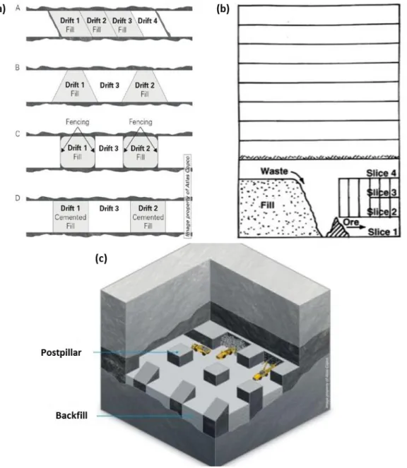
strike) mining (taken from Atlas Copco 2014) ... 12 Figure 2-3: Variations of cut-and-fill mining methods: (a) drift-and-fill mining; (b) Avoca
mining; (c) postpillar mining (a and c are taken from Atlas Copco 2014; b is taken from Bullock & Hustrulid 2001) ... 13 Figure 2-4: In-situ rockfill material (a) at Ballarat Gold mine (Sainsbury & Sainsbury 2014) and
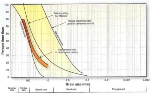
(b) at Louvicourt mine (Belem et al. 2013) ... 16 Figure 2-5: Particle size distribution of different sources of rockfill compared with Talbot grading
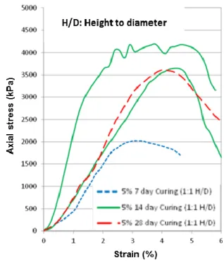
(Potvin et al. 2005) ... 17 Figure 2-6: Unconfined compressive stress-strain curves of CRF with 5% cement; samples from
the Ballarat mine in Australia (Sainsbury & Sainsbury 2014) ... 18 Figure 2-7: (a) Schematic diagram of a hydraulic fill stope with water ponding and a porous
barricade (Yang & Li 2016); (b) a stope under filling with CHF (Thompson et al. 2014a) .. 19 Figure 2-8: Particle size distribution of (a) full tailings sampled at the mill from nine Canadian
hard rock mines (Bussière 2007), and (b) full copper tailings, underflow (HF) and overflow (fines) (Potvin et al. 2005) ... 21 Figure 2-9: UCS of CHF as a function of cement content for several mines in Canada and
Australia (Hambley 2011) ... 22 Figure 2-10: Images of (a) lava-like flow of CPB entering a stope (Belem et al. 2013) and (b) a
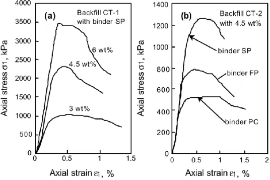
stope under filling with CPB (photo taken at the Goldex mine of Agnico Eagle Mines) ... 23 Figure 2-11: Unconfined compressive stress-strain curves of CPB after 112 days of curing for
different (a) binder contents and (b) types of binder (Belem et al. 2000) ... 26 Figure 2-12: Typical barricades made of: (a) arched permeable brick wall ; (b) timber; (c)
concrete; (d) shorcrete; (e) fibrecrete; (f) waste rock (a, b & e from Potvin et al. 2005; c & d from Grabinsky 2010; f from personal collection of Li Li) ... 28
Figure 2-13: The differential element used in the theory of Marston & Anderson (1913; from
McCarthy 1988) ... 31
Figure 2-14: (a) Failure caused by the downward movement of the yielding strip (ab) at the base of a sand layer; (b) Diagram illustrating assumptions on which computation of pressure in sand between two vertical surfaces of sliding is based (Terzaghi 1943) ... 32
Figure 2-15: A vertical backfilled opening with acting forces on an isolated layer element (Li et al. 2005) ... 35
Figure 2-16: Basis for calculating stresses in column of fill (Blight 1984) ... 37
Figure 2-17: Differential element in an inclined stope (adapted from Caceres 2005) ... 38
Figure 2-18: Schematic diagram of an inclined stope (Ting et al. 2011) ... 40
Figure 2-19: A vertical backfilled stope with partially submerged backfill (Li & Aubertin 2009a) ... 43
Figure 2-20: A vertical backfilled opening with forces acting on an isolated layer element (Li & Aubertin 2009b) ... 44
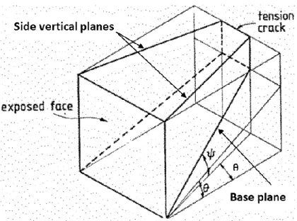
Figure 2-21: Sliding wedge model of the Mitchell et al. solution (adapted from Mitchell et al. 1982) ... 47
Figure 2-22: Wedge model of Dight & Coulthard (1980) (adapted from Dight & Coulthard 1980) ... 48
Figure 2-23: Wedge model of Mitchell et al. (1982) (Modified by Li & Aubertin 2009c) ... 52
Figure 2-24: Schematic representation of a vertical backfilled stope with a barricade in a fully drained condition (Li & Aubertin 2009c) ... 53
Figure 2-25: Schematic representation of a vertical backfilled stope with a barricade in a submerged condition (Li & Aubertin 2009d) ... 54
Figure 2-26: Numerical results of the distribution of (a) vertical and (b) horizontal stresses in FLAC (Li et al. 2003) ... 59
Figure 2-27: Vertical and horizontal effective (a) and total (b) stress along the VCL, obtained from numerical calculations and analytical solution (K = Ka) (Li & Aubertin 2009a) ... 60
Figure 2-28: Profiles of total (a) vertical and (b) horizontal stresses at the end of filling for different k values in a plane strain stope: (Fahey et al. 2009) ... 61 Figure 2-29: Evolution of (a) total vertical stress, (b) effective vertical stress and (c) PWPs (El
Mkadmi et al. 2014) ... 63 Figure 2-30: Stress (Pa) isocontours in two adjacent backfilled stopes obtained at the end of
filling the second stope (right-hand side; Falaknaz et al. 2015a) ... 64 Figure 2-31: Stress variation with backfill Poisson's ratio: along (a) VCL, (b) hanging wall and (c)
footwall in FLAC (Li & Aubertin 2009e) ... 66 Figure 2-32: Stress variations with the backfill friction angle: along (a) VCL, (b) hanging wall
and (c) foot wall in FLAC (from Li & Aubertin 2009e) ... 66 Figure 2-33: Normalized horizontal stress along the access drift (a) for a fully drained and (b)
submerged conditions, obtained with numerical and analytical solutions (Li & Aubertin 2009c) ... 68 Figure 2-34: Displacement isocontour of the exposed cemented fill in primary stope along the
vertical symmetry plane at failure (adapted from Chapter 5) ... 69 Figure 2-35: Distribution of pore water pressure in CPB; 10 days after filling (Li 2013a) ... 75 Figure 2-36: GeoStudio models of a backfilled stope: (a) with no wick drain but 5 drain holes on
the barricade; (b) with 5 wick drains in the stope and through the barricade (Li & Yang 2015) ... 76 Figure 2-37: Schematic view of the three consolidation columns filled with CPB at a mine
backfill plant (Belem et al. 2016) ... 78 Figure 2-38: (A) Total pressures during the filling for TEPCs on the barricade, in the drift and
under the brow as shown in (B) (Thompson et al. 2009) ... 85 Figure 2-39: TEP, PP and temperature measured at the (a) barricade and (b) Cage 3 in 685 Cayeli
Mine stope. TEP orientations H1 and H2 are horizontal and V refers to vertical pressure (Thompson et al. 2011a) ... 86
Figure 2-40: TEP, PP and temperature measured at the (a) barricade and (b) Cage 3 in 715 Cayeli Mine stope. TEP orientations H1 and H2 are horizontal and V refers to vertical pressure (Thompson et al. 2011a) ... 87 Figure 3-1: Schematic model of a typical backfilled stope with a pond above the fill surface
(adapted from Li & Aubertin 2009b) ... 92 Figure 3-2: Illustration of the generation of a pond above the fill surface in a stope backfilled with
hydraulic fill; the cross section shown is taken along the vertical symmetry plane through the drift axis (see Fig. 3-1) ... 93 Figure 3-3: Illustration of the water table drawdown in the stope and water flow within hydraulic
fill; the cross section is taken along the vertical symmetry plane through the drift axis (see Fig. 3-1) ... 94 Figure 3-4: Hydraulic functions of reservoir elements used for simulating the pond with
SEEP/W: (a) water retention curve; (b) permeability (data taken from Chapuis 2009) ... 96 Figure 3-5: A SEEP/W model of a backfilled stope with pond above the fill surface ... 97 Figure 3-6: Evolution of the water table height H with time t for different values of height Hw0,
calculated from the analytical [Eq. (3.6) in 2D] and numerical calculations (Case 1, Table 3-1) ... 99 Figure 3-7: Evolution of water table height H with time t for different values of backfill height Hb,
obtained with the analytical [Eq. (3.6) in 2D] and numerical calculations (Case 2, Table 3-1) ... 99 Figure 3-8: Evolution of the water table height H with time t for different values of length l,
obtained with the analytical [Eq. (3.6) in 2D] and numerical calculations (Case 3, Table 3-1) ... 100 Figure 3-9: Evolution of the water table height H with time t for different values of ksat, predicted
by the analytical [Eq. (3.6) in 2D] and numerical calculations (Case 4, Table 3-1) ... 101 Figure 3-10: Evolutions of the water table height H with t; obtained from Eq. (3.6) (in 3D) with
different ratios L/Ld and from numerical results (Case 5, Table 3-1) with values of reduced
Figure 3-11: Evolution of ubase obtained from Eq. (3.3) and numerical simulations for (a) Case 0,
(b) Case 5b and (c) Case 5c; Eq. (3.3) is calculated with different ratios L/Ld and numerical
results with values of reduced ksat in the drift (see Table 3-1 for details) ... 102
Figure 3-12: Vectors of hydraulic velocity when the water table is near the (a) initial height t = 10 h and (b) settled fill surface t = 97.6 h, obtained from SEEP/W modelling with uniform ksat
of backfill (Case 0, Table 3-1) ... 104 Figure 3-13: Isocontour of pore water pressure for the water table close to a stable transient state
when it is near the (a) initial height and (b) settled fill surface, obtained with uniform ksat
value of backfill (Case 0, Table 3-1) ... 105 Figure 3-14: Isocontour of pore water pressure for the water table near the (a) initial height and (b)
settled fill surface, obtained with reduced ksat of backfill in the drift (Case 5b, Table 3-1) 106
Figure 3-15: Distributions of PWP along the VCL of stope at different times obtained from numerical modelling with (a) uniform ksat (Case 0, Table 3-1) and (b) reduced ksat in the drift
(Case 5b, Table 3-1) ... 107 Figure 3-16: Distributions of PWP along the HCL of drift at different times obtained from
numerical modelling with (a) uniform ksat (Case 0, Table 3-1) and (b) reduced ksat in the drift
(Case 5b, Table 3-1) ... 108 Figure 4-1: Schematic view of a typical backfilled stope with a trapezoidal WRB (adapted from
Li & Aubertin 2011) ... 120 Figure 4-2: Waste rock barricade with various acting forces; symmetric forces acting on the other
side (CL and SL) of the WRB are not shown here ... 121
Figure 4-3: A model for internal translation stability analysis of the WRB ... 124 Figure 4-4: Variation of LBT with h for local stability analysis [Eq. (4.6)] ... 125
Figure 4-5: Variation of the required top length LBT obtained by Eqs. (4.5) and (4.8) as a function
of δ ... 126 Figure 4-6: Conceptual model of the backfilled stope with a trapezoidal WRB ... 128 Figure 4-7: WRB model built with FLAC, showing the discretization and boundary conditions ... 129
Figure 4-8: Displacement vectors of WRB with (a) a relatively smooth interface ( = 20°, LBT =
2.5 m), and (b) a rougher interface ( = 30°, LBT = 1.5 m) ... 130
Figure 4-9: Typical variation of the horizontal displacement at point M (see Fig. 4-7) as a function of the barricade top length ... 131 Figure 4-10: Contours of horizontal displacement within the WRB, for LBT equal to (a) 1.6 m and
(b) 1.5 m ... 131 Figure 4-11: Comparison of the required length LBT obtained from the analytical solutions [Eq.
(4.11) with CM = 1.5] and numerical simulations for different values of δ ... 132
Figure 4-12: Comparison between the analytical solution [Eq. (4.11)] with CM = 1.5, γwr = γb =
19.62 kN/m3, K = Ka and FS = 1.0) and numerical simulations. The calculations give the
variation of the required LBT for different values of δ with an increase in (a) waste rock
strength ', (b) CPB height H in the stope, (c) barricade height Hd, and (d) CPB height H in
the stope ... 134 Figure 4-13: Variation of the required LBT with for different values of (a) upstream slope angle
α1 and downstream slope angle α2, (b) drift width Ld and height Hd, and (c) internal friction
angles ’ ... 135 Figure 5-1: Sliding wedge model of the Mitchell et al. solution (adapted from Mitchell et al.
1982) ... 150 Figure 5-2: The FLAC3D model of exposed backfill in a primary stope; the open face, symmetry
plane and discretization are shown ... 155 Figure 5-3: Displacement profiles along the stope height (line MN in Fig. 5-2) for different
values of fill cohesion c; simulations conducted with H = 45 m, B = 6 m, L = 9 m, ’ = 35°, ν = 0.3, = 18 kN/m3 and E = 300 MPa ... 157 Figure 5-4: Displacements isocontours of the exposed backfill along the vertical plane of
symmetry for cohesion c equals to (a) 25 kPa and (b) 24 kPa; simulations conducted with H = 45 m, B = 6 m, L = 9 m, ’ = 35°, ν = 0.3, = 18 kN/m3 and E = 300 MPa ... 158
Figure 5-5: Displacements isocontours of the exposed backfill along the vertical plane of symmetry at a critical state when the stope width B changes from 10 to 25 m; simulations conducted with H = 45 m, L = 9 m, ’ = 35°, ν = 0.3, = 18 kN/m3 and E = 300 MPa ... 159 Figure 5-6: The modified wedge model with a vertical potential tension crack showing various
acting forces (adapted from Li 2014a) ... 160 Figure 5-7: Required fill cohesion c obtained from Eq. (5.15b) and four other analytical solutions,
and numerical simulations, for different values of stope (a) height H (L = 9 m, B = 6 m), (b) width B (H = 45 m, L = 9 m), and (c) length L (H = 45 m, B = 6 m). Calculations done with Eq. (5.15b) for FS = 1, p0 = 0, ’ = δ = 35°, rs = 1, = 18 kN/m3; simulations made with ’ =
35°, ν = 0.3, = 18 kN/m3, E = 300 MPa, T0 = 0 and UCS/10 ... 162
Figure 5-8: Required fill cohesion c obtained from Eq. (5.15b) and from numerical simulations (obtained with a tension cutoff T0 of zero and UCS/10), for different values of friction angle
’. Calculations made with Eq. (5.15b) for FS = 1, H = 45 m, B = 6 m, L = 9 m, p0 = 0, δ =
’, rs = 1, = 18 kN/m3; simulations made with E = 300 MPa and the same backfill unit
weight and stope geometry ... 163 Figure 5-9: (a) Required c (for FS = 1) and (b) minimum FS (for c = 35 kPa) obtained from Eq.
(5.15) as a function of surcharge p0 for different values of rs; calculations made with H = 50
m, L = 10 m, δ = ’ = 30° and = 18 kN/m3 ... 164 Figure 5-10: (a) Required c (for FS = 1) and (b) FS (for c = 35 kPa) obtained from Eq. (5.15) as a
function of adherence ratio rs for different values of ’. Calculations made with H = 50 m, L
= 10 m, p0 = 0, δ = ’ and = 18 kN/m3 ... 165
Figure 5-11: (a) Required c (for FS = 1) and (b) FS (for c = 35 kPa) obtained from Eq. (5.15) as a function of adherence ratio rs for different values of δ. Calculations made with H = 50 m, L
= 10 m, p0 = 0, ’ = 30° and = 18 kN/m3 ... 165
Figure 6-1: Conceptual model (a) and the corresponding FLAC model (b) of a backfilled opening ... 181
Figure 6-2: Horizontal (a) and vertical (b) stress (in Pa) contours of FLAC simulations conducted for independent (Case 0) and interrelated (Case 0’) values of ν and ϕ’ (see Table 6-1 for details) ... 183 Figure 6-3: Stress distributions (a) along the VCL and (b) near the RW in the backfill for
independent (Case 0) and related (Case 0’) values of ν and ϕ’ (see Table 6-1 for details) .. 184 Figure 6-4: Vertical profiles of K and Kps (a) along the VCL and (b) near the RW, for
independent (Case 0) and related (Case 0’) values of ν and ϕ’ (see Table 6-1 for details) .. 185 Figure 6-5: Vertical profiles of K and Kps (a) along the VCL and (b) near the RW for different B
values for independent values of ν and ϕ’ (Case 1 in Table 6-1) ... 186 Figure 6-6: Vertical profiles of K and Kps (a) along the VCL and (b) near the RW for different E
values for independent values of ν and ϕ’ (Case 2 in Table 6-1) ... 186 Figure 6-7: Vertical profiles of K and Kps (a) along the VCL and (b and c) near the RW for
different ’ values with constant ν value (Case 3 in Table 6-1) ... 187 Figure 6-8: Vertical profiles of K and Kps (a) along the VCL and (b and c) near the RW for
different ν values when disconnected with ϕ’ value (Case 4 in Table 6-1). ... 188 Figure 6-9: Vertical profiles of K and Kps (a) along the VCL and (b) near the RW for different B
values for related ν and ϕ’ values (Case 1’ in Table 6-1) ... 189 Figure 6-10: Vertical profiles of K and Kps (a) along the VCL and (b) near the RW for different E
values for related values of ν and ϕ’ (Case 2’ in Table 6-1) ... 189 Figure 6-11: Vertical profiles of K and Kps (a) along the VCL and (b and c) near the RW for
different ’ values related to ν values (Case 3’ in Table 6-1) ... 190 Figure 6-12: Distributions of (a) Kps and (b) K across width B at different heights for related
values of ν and ϕ’ (Case 0’ in Table 6-1) ... 191 Figure 6-13: Vertical profiles of Kps (= ’3/’1) near the walls (RW) as a function of angle δ’ for
Figure 6-14: Vertical profiles of Kps (= ’3/’1) near the walls (RW) as a function of ν for angle
δ’ = ϕ’ (a), 2/3ϕ’ (b), 1/3ϕ’ (c) and 0 (d), obtained with related values of ν and ϕ’ (Case 4’ in Table 6-1) ... 193 Figure 6-15: Mohr-Coulomb plane showing the stress states for the backfill along the VCL of the
opening ... 194 Figure 6-16: Vertical profiles of stress ratios Kps = K along the VCL for different ’ values with
LIST OF SYMBOLS AND ABBREVIATIONS
SymbolsB width of the stope or opening (m)
Bt equivalent width of the sliding wedge in the presence of a tension crack (m)
C a constant representing the hydraulic and geometric characteristics of a stope with hydraulic fill and porous barricade (s-1)
CU coefficient of uniformity
CM calibration factor
c cohesion (kPa)
c' effective cohesion (kPa)
ci cohesion of fill-rock interface (kPa)
cb cohesion along the back wall (kPa)
cs cohesion along the sidewalls (kPa)
D60, D10 size at which 60% and 10% of particles pass the sieve (mm)
dmax maximum particle size (mm)
E Young’s modulus (MPa or GPa)
Er Young’s modulus of the rock mass (GPa)
e void ratio
H height of the stope or opening (m) H* equivalent height of the wedge (m) Hd drift/ barricade height (m)
Hw pond height in the stope (m)
Hw0 initial height of the pond (m)
Ht depth of the tension crack (m)
ID density index (%)
K coefficient of earth pressure
Ka Rankine’s active pressure coefficient
Kp Rankine’s passive pressure coefficient
K0 coefficient of earth pressure at-rest
(K0)ϕ’ coefficient of earth pressure at-rest based on Jaky’s equation
(K0)ν coefficient of earth pressure at-rest defined by the Poisson’s ratio
Kps principal stress ratio
k hydraulic conductivity (m/s)
ksat saturated hydraulic conductivity (m/s)
Kn normal stiffnesses of interface elements (GPa/m)
Kt shear stiffnesses of interface elements (GPa/m)
L stope length (m)
LB average length of the waste rock barricade (m)
LBT top length of waste rock barricade (m)
LBB base length of waste rock barricade (m)
Ld drift/ barricade width (m)
l distance of the barricade to the drawpoint (m)
n porosity
ns porosity of the settled hydraulic fill
P solid weight content of backfill (%)
p0 surcharge exerted on the backfill top surface (kPa)
rb adherence ratio along the back wall
rs adherence ratio along the sidewalls
Ss shear force acting along the sidewalls (kN)
St shear force acting along the tension crack (kN)
T total time needed to drain the pond (s or h) t a transient time (s or h)
T0 tensile strength of cemented backfill
u pore water pressure (kPa)
ubase pore water pressure at the stope base (kPa)
V volume (m3)
W weight of the sliding wedge (kN)
α inclination angle of the sliding plane to the horizontal (°)
α1 upstream slope angle of waste rock barricade on the stope side (°)
α2 downstream slope angle of waste rock barricade on the drift side (°)
β inclination angle of the stope to the horizontal (°) θw volumetric water content
ϕ internal friction angle (°)
ϕ’ effective internal friction angle (°)
interface friction angle (°)
’ effective interface friction angle (°)
c critical interface friction angle (°)
Ψ dilation angle (°)
h horizontal stress (kPa) v vertical stress (kPa)
’h horizontal effective stress (kPa) ’v vertical effective stress (kPa)
ζ1 major principal stress (kPa)
ζ3 minor principal stress (kPa)
ζ’1 major effective principal stress (kPa)
ζ’3 minor effective principal stress (kPa)
γ unit weight of the backfill (kN/m3) γw unit weight of water (kN/m3)
γb unit weight of the cemented paste backfill (kN/m3)
γwr unit weight of the waste rock (kN/m3) r unit weight of the rock mass (kN/m3) sat unit weight of saturated backfill (kN/m3) sub unit weight of submerged backfill (kN/m3)
ν Poisson’s ratio
νr Poisson’s ratio of rock mass
λ a parameter for relating the internal friction angle ϕ’ and Poisson’s ratio ν of granular materials
Abbreviations
CHF cemented hydraulic fill CRF cemented rock fill CPB cemented paste backfill FDM finite difference method FEM finite element method
FS factor of safety
FW footwall
HAR high aspect ratio HF hydraulic fill
HW hanging wall
LAR low aspect ratio
MM Modified Mitchell
PWP pore water pressure
RF rock fill
RW rock wall
UCS unconfined compressive strength VCL vertical center line
LIST OF APPENDICES
Appendix A – An investigation of the relationships between K0, ϕ’ and ν for granular materials
... 243 Appendix B – Validation of SEEP/W using variable-head permeability test ... 266 Appendix C – Validation of codes FLAC and FLAC3D ... 271 Appendix D – Sensitivity analyses related to Chapter 3 ... 281 Appendix E – Sensitivity and parameric analyses related to Chapter 4 ... 285 Appendix F – Sensitivity and parameric analyses related to Chapter 5 ... 292 Appendix G – Sensitivity and parameric analyses related to Chapter 6 ... 304 Appendix H – Additional results related to Chapter 6 ... 307
CHAPTER 1
INTRODUCTION
Mining is a major component of Canada’s economy. However, mining generates substantial amount of solid wastes, mainly in the form of tailings and waste rock. Tailings are crushed rock produced by mineral extraction and are typically disposed as slurry. Waste rock is the coarse grained material excavated to create mine openings; it has no economic value.
Tailings and waste rock are typically stored on the surface in tailings impoundments and waste rock piles. These structures greatly increase the footprints of mining operations and can pose significant environmental and geotechnical issues. As a priority for the mining industry and society, their safe, environmentally responsible, long-term management is a significant challenge (e.g., Aubertin et al. 2002, 2011, 2016). Underground mine stope backfilling with mine wastes can significantly reduce the amount of wastes disposed on the surface. This can be an environmentally friendly and responsible solution for mine waste management.
In recent decades, underground mine stope filling has been increasingly used worldwide and it has become a common practice. Besides the environmental benefits, backfilling’s advantages also include improved regional ground stability, ore recovery, ore dilution and ventilation (Thomas 1979; Hassani & Archibald 1998; Potvin et al. 2005; Hambley 2011).
In underground mining, the application of mine backfill largely depends on the mining methods employed. In open stoping, the backfill is commonly used to stabilize the rock mass and help recover the (vertical) rib pillars (secondary stopes); this backfill is usually called “delayed backfill”. Cemented backfill is used to recover (horizontal) sill pillars. In cut-and-fill mining, backfill usually serves as a working floor or as a roof for further extraction; it also serves to increase the rock mass stability. When the backfill contains water and/or cement - mostly for rib and sill pillar recovery in open stoping or for the underhand cut-and-fill mining, barricades need to be built in the lower drift (near the drawpoint) to retain the hydraulically transported saturated fill. Several critical issues associated with the design of the backfill and barricades are raised:
How to design the barricade?
What is the optimal strength of the backfill exposed vertically on one side or exposed horizontally at the base?
The first theme is mostly related to the backfill behavior at very early time (shortly after the filling), while the second to the behavior of the backfill at longer time (typically a few weeks after filling). The realization of these tasks requires a good understanding of the geomechanical behavior of the backfill and its interactions with the confining structures (i.e., rock walls and barricades). The complex interactions between backfill and confining structures constitute the problems to be investigated, which are briefly presented in the following.
1.1 Definition of the problem
The primary concern related to stope filling is the barricade stability shortly after the placement of backfill. A number of documented failures indicate that the barricade design remains a major challenge (e.g., Bloss & Chen 1998; Yumlu & Guresci 2007). More work is needed to evaluate the critical backfill pressure exerted on the barricade and its design. This requires, in turn, a good understanding of pore water pressures (PWP) and total (and effective) stresses in the backfilled stope and drift where the barricade is built.
Recently, barricades constructed with waste rock has become popular in Canada and elsewhere due to their simple and low-cost construction, compared to the traditional barricades made of bricks, concrete blocks, or reinforced shotcrete. However, solutions developed for traditional barricades are not directly applicable to waste rock barricades. It is thus necessary to develop new methods for sizing such waste rock barricades.
A second crucial issue is the stability of the exposed cemented fill in the primary stope during the subsequent secondary recovery (which usually occurs a few weeks after filling). The failure of the exposed fill can lead to ore dilution or serious instability issues. These can be reduced or avoided by increasing the binder usage (cement, fly ash, slag, pozzolan, etc.); but the associated cost considerably increases. Thus, the question is how to estimate the minimum (optimal) required strength of cemented fill upon vertical exposure. This demands stability analysis of exposed fill with regard to its interactions with the remaining three sidewalls.
Another issue is how the ground stability can be improved by the backfill. This requires a comprehensive understanding of the interactions between the backfill and confining rock walls. The stress state within the backfilled stopes and adjacent rock mass should be correctly evaluated, which can be done by theoretical (closed-form solutions) and numerical analyses. To this end,
analytical solutions are in high demand by mining engineers. Most existing analytical solutions involve a parameter called earth pressure coefficient K (= ζ’h/ζ’v). Its value can largely influence
the estimated stress state in backfilled openings, which in turn affects various design aspects of mine backfill and barricade. More work is needed to better understand this aspect (as will be demonstrated below).
1.2 Thesis objectives
The primary objective of this project is to investigate the geomechanical behavior of backfill placed in vertical mine stopes and similar openings. More specifically, the project focuses on the behavior of the backfill at very early time for sizing waste rock barricades, on the behavior of cemented fills at longer time before and after exposure on one side, and on the stress state within the confined fill itself. The following sub-objectives have been specifically addressed:
1) Investigate the evolution of the water table and PWP in stopes with hydraulic fill
Develop 3D analytical solutions to describe the evolution of the water table and PWPs in the stope;
Conduct numerical simulations to evaluate the PWPs in stopes and drifts, and to validate the proposed analytical solutions.
2) Sizing of waste rock barricades constructed to retain paste fill during stope filling:
Propose 3D analytical solutions for sizing waste rock barricades with respect to their global and local stability;
Perform numerical simulations to identify the failure mechanism and instability criterion of waste rock barricades, and to verify the proposed solutions.
3) Assess the stability of cemented mine backfill upon a vertical exposure:
Develop improved analytical solutions for estimating the required strength and factor of safety of mine backfill with an open face;
Conduct numerical simulations (with related values of internal friction angle ϕ’ and Poisson’s ratio ν of the fill) to assess the failure mode and instability criterion of exposed mine backfill, and to validate the proposed analytical solutions;
4) Numerical analysis of stress state in vertical backfilled openings with cohesionless fills:
Evaluate the earth pressure coefficient K (= ζ’h/ζ’v) in backfilled openings to estimate the
stress distribution within fills;
Investigate the principal stress ratio Kps (= ζ’3/ζ’1)in backfilled openings to evaluate the
backfill state;
Assess the effect of using related and independent backfill parameters ϕ’ and ν on the stress state and coefficients K and Kps; and
Analyze the effect of interface elements and their frictional properties on the stress state and coefficients K and Kps.
1.3 Contributions
The main scientific contributions of this research project include the following four articles published in or submitted to peer-reviewed journals:
Article 1:
Yang PY & Li L. (2016) Evolution of water table and pore water pressure in stopes with submerged hydraulic fill. ASCE International Journal of Geomechanics. Accepted with changes in October 2016. This article is presented in Chapter 3.
Article 2:
Yang PY, Li L, Aubertin M, Brochu-Baekelmans M & Ouellet S. (2016a) Stability analyses of waste rock barricades designed to retain paste backfill. ASCE International Journal of Geomechanics, doi: 10.1061/(ASCE)GM.1943-5622.0000740, 04016079. This article is presented in Chapter 4.
Article 3:
Yang PY, Li L & Aubertin M. (2016b) A new solution to assess the required strength of mine backfill with a vertical exposure. ASCE International Journal of Geomechanics. Submitted in September 2016. This article is presented in Chapter 5.
Yang PY, Li L & Aubertin M. (2016c) A comprehensive numerical analysis of stress ratios in vertical backfilled openings. ASCE International Journal of Geomechanics. Submitted in November 2016. This article is presented in Chapter 6.
The following three articles have also been published in or to be submitted to peer-reviewed journals in the course of this project:
Yang PY, Li L, Aubertin M & Tiwari A. (2016d) An investigation of the relationships between K0, ϕ’ and ν for granular materials. To be submitted. Main results are presented in Appendix A.
Yang PY & Li L. (2015) Investigation of the short-term stress distribution in stopes and drifts backfilled with cemented paste backfill. International Journal of Mining Science and Technology, 25(5): 721-728.
Li L & Yang PY. (2015) A numerical evaluation of continuous backfilling in cemented paste backfilled stope through an application of wick drains. International Journal of Mining Science and Technology, 25(6): 897-904.
The following two conference papers have also been published in the course of this project: Yang PY, Brochu-Baekelmans M, Li L & Aubertin M. (2014) An improved solution for sizing
barricades made of waste rock to retain cemented paste backfill. In Proceedings of 67th Canadian Geotechnical Conference, Regina, SK, Canada.
Yang PY & Li L. (2014) A 3D analytical solution for the short-term stress distribution in backfilled stopes and on barricades. In Proceedings 67th Canadian Geotechnical Conference, Regina, SK, Canada.
This project contributes to better addressing major geomechanical challenges encountered in underground stope filling, including the design of support structures (barricades) and exposed cemented backfill. Analytical and numerical solutions presented in this project provide tools to help evaluate the evolution of the water table and PWPs in stopes with hydraulic fill, size waste rock barricades for retaining paste fill, and assess the stability of exposed cemented backfill. These analytical (closed form) solutions can be useful for mining engineers, at least in the preliminary design. Other components of this research also lead to improved assessment of stress state in backfilled openings; this may help increase the productivity and reduce the associated risks in underground mining.
1.4 Content of this thesis
The scope of this research is relatively broad due to the number and complex nature of the issues involved.
The literature review is presented in Chapter 2; it includes review of the state of knowledge on the following themes:
Underground mining methods employing backfills;
Classification of mine backfills and their typical geomechanical properties and characteristics;
Typical barricades used for retaining mine backfill;
Analytical solutions for stress estimation in backfilled stopes and on barricades;
Analytical methods to assess the stability of cemented fill with vertical exposure;
Numerical simulations for evaluating the stress state and stability of backfilled stopes;
Experimental tests for assessing backfill stress in stopes and barricade drifts.
Chapters 3 to 6 are presented in the form of manuscripts which have been published or submitted to peer-reviewed journals.
Chapter 3 (Article 1) presents 3D analytical solutions for describing the evolution of the water table and pore water pressures (transient seepage) in stopes with submerged hydraulic fill. This corresponds to the condition when a pond is generated on the backfill surface by the self-weight consolidation of the fill particles. The proposed solutions are verified using numerical simulations by modelling the transient seepage as the water table drops in the stope. The main influencing factors on the evolution of the water table and pore water pressures are evaluated and compared for the two approaches.
Chapter 4 (Article 2) presents the development of a more complete 3D analytical solution for sizing trapezoidal barricades made of waste rock to retain cemented paste backfill, considering both global and local stability. The failure mechanism and an explicit instability criterion of the waste rock barricade are identified from numerical simulations conducted with interface elements. The proposed solutions are then calibrated and validated using numerical results for
representative geometrical and mechanical properties of barricades. In this paper, the internal friction angle ϕ’ and Poisson’s ratio ν of waste rock are taken as independent parameters, as is commonly assumed in numerical analyses. Sample calculations are also presented to illustrate the application of this solution.
Chapter 5 (Article 3) presents the development of a new analytical solution for assessing the stability of mine backfill with a vertical exposure, based on a new failure mode observed from numerical simulations and existing experimental tests. An explicit instability criterion for side-exposed backfill is introduced based on numerical results. The validation of the new solution using numerical models is then illustrated for different stope geometries and backfill properties. For numerical simulations presented here, the internal friction angle ϕ’ and Poisson’s ratio ν of backfill are related using the correlation proposed in Appendix A, based on the consideration of a unique and consistent value of K0.
Chapter 6 (Article 4) contains the main numerical results for evaluating the earth pressure coefficient K and principal stress ratio Kps near the center and walls of openings backfilled with
granular (no cohesion) fills. The simulations are conducted with both independent and related values of internal friction angle ϕ’ and Poisson’s ratio ν of the backfill. The effect of various mechanical and geometric characteristics on the stress ratios (K and Kps) is evaluated. The
backfill stress state is assessed with the principal stress ratio Kps based on the Mohr-Coulomb
criterion. The interface elements are also used to assess the effect of fill-wall contacts and its properties on the stress state of backfill.
Chapter 7 provides a summary and general discussion on the main results of the research. The procedure and validation of numerical modelling are also discussed. Conclusions and recommendations for further studies can be found in Chapter 8.
This thesis also includes an extensive References list and Appendices that present the validation of SEEP/W, FLAC and FLAC3D and complementary results on various aspects of this research. Besides, the Appendix includes additional results (Appendix A) that proposes a relationship between the internal friction angle ϕ’ and Poisson’s ratio ν (at small strains) for granular materials, based on the two basic approaches for defining the earth pressure coefficient at-rest K0.
This correlation is tested using a number of conventional triaxial compression tests results taken from the literature on granular materials.
CHAPTER 2
LITERATURE REVIEW
This chapter first reviews the major underground mining methods where backfills are commonly used for various engineering purposes. Typical mine backfills, i.e., rockfill, hydraulic fill and paste fill, are then reviewed with respect to their typical physical, hydraulic and mechanical properties. A review of typical barricades used for retaining backfill in place is also presented. This chapter then presents the state of knowledge on the stress state in backfilled stopes and drifts, and the stability design of the barricade and cemented backfill with vertical exposure.
2.1 Mining with backfill
In order to convert a mineral resource to a probable or proven reserve, a preliminary feasibility study needs to be undertaken, which includes selecting mining methods. In practice, the selection of a mining method is largely based on the characteristics of the deposit and rock mass. In some mines, more than one method is used synergistically.
Mining methods are basically divided into surface mining methods (e.g., open-pit mining, strip mining) and underground mining methods (Hartman & Britton 1992; Darling 2011). The latter can include self-supported methods (room-and-pillar mining, sublevel stoping, shrinkage stoping, vertical crater retreat), artificially supported methods (cut-and-fill mining), and caving method (longwall mining, sublevel caving and block caving). Details on these mining methods can be found in the SME Mining Engineering Handbook (Hartman & Britton 1992; Darling 2011). A number of variants have been created based on basic mining methods to account for the uniqueness of each mineral deposit (Hamrin 2001; Hustrulid & Bullock 2001). This subsection is aimed at summarizing briefly the characteristics of the major mining methods in which backfill can be employed. Emphasis is given here to the type of backfill that can be used and its functions, filling sequences, infrastructures associated with filling, and aspects to consider in backfill design.
2.1.1 Self-supported methods
In self-supported (or naturally supported) methods, ore (or waste rock) pillars are left (and definitely lost for most cases) to stabilize rock walls. These usually apply to low-grade deposits where the increase in ore recovery does not justify the cost of backfill (Potvin et al. 2005).
However, backfill is sometimes used to recover the pillars or secondary stopes following the extraction of the rooms and primary stopes. Such secondary recovery can be classified as artificially supported method due to the use of backfill. Here, the application of backfill in such combined method is included under self-supported method.
2.1.1.1 Room-and-pillar mining
In room-and-pillar (R&P) mining, pillars are left to support the hanging wall and back (roof) as rooms (horizontal openings) are extracted (Bullock 2011). This method is used in subhorizontal mineral deposits with uniform and limited thickness (Hamrin 2001).
In some cases, ore pillars need to be recovered which involves placing cemented or uncemented fill among pillars up to the back of a room. The backfill provides ground support and helps control the back-floor convergence (e.g., Hunt 1988; Roberts et al. 1998; Lane et al. 2001; Tesarik et al. 2009). The filling usually starts from the perimeter pillars towards the center of the filled area. Barricades (or fill fences) are built between perimeter pillars to retain the fill. The associated concerns are the barricade stability and the minimum required fill strength for self-standing during the extraction of ore pillars.
2.1.1.2 Sublevel stoping
Sublevel stoping is used in more than 60% underground mines in North America (Pakalnis & Hughes 2011). It can be applied with competent rock mass and steep (from 50° to 90°) ore bodies. The most commonly used sublevel stoping methods include blasthole stoping, long-hole stoping, shrinkage stoping and vertical crater retreat.
In blasthole stoping, multiple drilling levels (sublevels) are created between main levels. Holes (20-30 m in length) are drilled by top-hammer drills in the sublevel drifts. The blasted ore is mucked from the drawpoints at the stope base (Hamrin 2001; Darling 2011). The long-hole stoping can be regarded as a large-scale variation of blasthole stoping. The longer (up to about 100 m), greater and straighter holes are drilled by in-the-hole (ITH) technique (Hamrin 2001). The multiple drilling levels are thus eliminated.
In shrinkage stoping, the ore is removed upwards with horizontal slices from the stope base. About 35% of blasted ore is first drawn off while the remnant blasted ore provides working floor and support of rock walls for further extraction (temporarily fulfilling some roles of backfill).
When the blasted ore is totally drawn out, the stope may be filled (mostly with waste rock from development) or left open.
Vertical crater retreat (VCR) is a patented mining method developed by INCO and CIL Inc. VCR first involves an undercut to create a horizontal slot. ITH holes are drilled from an upper level to the slot. The ore is then blasted upwards in slices. Only a portion of the blasted ore is mucked at drawpoints; VCR can thus be regarded as a form of shrinkage stoping. Vertical block mining (VBM) can be regarded as a variant of VCR. With VBM, the extraction is usually performed in larger slices (e.g., three or four; Emad et al. 2014, 2015a). Each slice is blasted and mucked out prior to blasting the next lift.
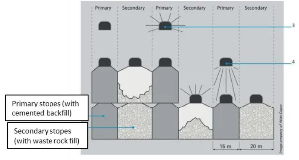
Backfill can be applied in sublevel stoping and its variants. For blasthole stoping, long-hole stoping and shrinkage stoping, backfill can be used to increase ground stability and/or to recover ore pillars. If pillar recovery is unnecessary, stopes can be filled with uncemented fill. It is then possible to increase the ore recovery by reducing the size of pillars. When pillars must be recovered (as is the case of VCR), it is customary to divide the stopes into primary and secondary stopes. The former are filled with cemented backfill (i.e., cemented rock, hydraulic or paste fill) to form man-made rib pillars, while the latter are filled with either uncemented or low cement content backfill or a mix of uncemented (upper part) and cemented (lower part) fill (Fig. 2-1).
Figure 2-1: Illustration of open stope mining showing the backfilling of primary and secondary stopes (taken from Atlas Copco 2014)
Backfilling may proceed in a checkerboard pattern following the mining sequence. The design of backfill strength is largely dependent on the later extraction, number of exposed faces, stope geometry and stability of rock mass. The cemented fill is required to be self-standing upon excavation of an adjacent secondary stope. A critical issue is how to estimate the minimum required strength of the exposed (unsupported) cemented fill. Current backfill design is mostly based on an analytical solution proposed by Mitchell et al. (1982). Several updates have been made by Zou & Nadarajah (2006), Dirige et al. (2009), Li & Aubertin (2012, 2014), and Li (2014a, 2014b).
Another critical concern is how to design the barricade, built in the drift near the drawpoint, to retain backfill during and after filling. Different types and sizes of barricades can be used based on the backfill type, filling sequence, rising rate, required strength, drainage capacity, and materials available (e.g., Mitchell et al. 1975; Soderberg & Busch 1985; Beer 1986; Kuganathan 2001, 2002a, 2002b; Revell & Sainsbury 2007b; Li & Aubertin 2009c, 2009d, 2011; Li 2013; Yang et al. 2014, 2016a; Rajeev & Sivakugan 2016).
These solutions (analytical and numerical) for assessing the stability of exposed cemented fill and barricade design will be reviewed in Sections 2.4 and 2.5.
2.1.2 Artificially supported methods
In artificially supported methods, the backfill (often combined with pillars) is used to control rock wall stability and mine near-field displacements (Brady & Brown 2004). In most cases, artificially supported mining designates cut-and-fill mining. Strictly, a cut-and-fill mining means a cut followed by immediately filling (Hartman & Britton 1992; Darling 2011). However, rooms or stopes in self-supported method are filled only after the entire stope is extracted; the backfill used is thus called “delayed backfill” (Stephan 2011).
2.1.2.1 Cut-and-fill mining
When the rock mass and ore conditions do not permit the creation of large stopes, mined-out voids have to be filled concurrently with extraction. Cut-and-fill (C&F) mining is designed for such conditions. During extraction, voids are usually filled with cemented or uncemented fill once a slice of ore is mined out. The fills serve as a working floor or roof for further extraction and also stabilize the rock mass. In the former case, the fill strength should be designed to
support machine operation and to minimize ore dilution (Belem & Benzaazoua 2008; Stephan 2011). The use of hydraulic fill and paste fill requires more management (e.g., constructing barricades) at multiple points of drainage. Two main variations of C&F mining are first described based on the rock mass conditions and extraction sequence. Other variations, such as drift-and-fill mining, Avoca mining and postpillar mining, are presented with more details in Yang (2015). Overhand C&F method (Fig. 2-2a) is used when the condition of ore bodies is fairly good. Usually, uncemented fill (e.g., hydraulic or rock fill) provides a working floor (platform) for the bottom-up ore extraction. A top layer of cemented fill is often used to facilitate the machine operation. In some cases, several extractions are operated simultaneously at different locations. A horizontal sill (or crown) pillar is used to separate extractions in two adjacent levels. To recover the sill pillar, it is necessary to construct an overlying sill mat that is usually made of cemented fill (reinforced with steel bar or not; Bullock & Hustrulid 2001). Such sill mat is critical to the global stability of stope once the sill pillar is removed (e.g., Mitchell 1991; Oulbacha 2014; Sobhi & Li 2015).
Figure 2-2: Schematic layout for (a) overhand and (b) underhand C&F (side view along the strike) mining (taken from Atlas Copco 2014)
Underhand C&F method may be used when the quality of rock mass and orebody is poor. This method involves a top-down excavation and filling sequence. A sill mat is required at the stope base, while the upper portion is filled with uncemented fill or left unfilled (Fig. 2-2b). Another option is to fill the whole stope with cemented backfill (similar to a thick sill mat). With both options, the sill mat serves as a working roof for miners when excavating the underlying stopes.