ÉCOLE DE TECHNOLOGIE SUPÉRIEURE UNIVERSITÉ DU QUÉBEC
DESIGN, DEVELOPMENT AND TESTS IN REAL TIME OF CONTROL METHODOLOGIES FOR A MORPHING WING IN WIND TUNNEL
BY
Michel Joël TCHATCHUENG KAMMEGNE
MANUSCRIPT-BASED PRESENTED TO ÉCOLE DE TECHNOLOGIE SUPÉRIEURE IN PARTIAL FULFILLMENT FOR THE DEGREE
OF DOCTOR OF PHILOSOPHY Ph.D.
MONTREAL, JULY 28TH 2016
© Copyright
Reproduction, saving or sharing of the content of this document, in whole or in part, is prohibited. A reader who wishes to print this document or save it on any medium must first obtain the author’s permission.
BOARD OF EXAMINERS
THIS THESIS HAS BEEN EVALUATED BY THE FOLLOWING BOARD OF EXAMINERS
Dr. Ruxandra Mihaela Botez, Thesis Supervisor
Department of Automated Production Engineering at École de technologie supérieure
Dr. Martine Dubé, President of the Board of Examiners
Department of Mechanical Engineering at École de technologie supérieure
Dr. Vincent Duchaine, Member of the jury
Department of Automated Production Engineering at École de technologie supérieure
Dr. Franck Cazaurang, External Evaluator Université de Bordeaux
THIS THESIS WAS PRENSENTED AND DEFENDED
IN THE PRESENCE OF A BOARD OF EXAMINERS AND THE PUBLIC MONTRÉAL JUNE 21ST 2016
ACKNOWLEDGMENTS
I would like to thank to my thesis supervisor, Dr. Ruxandra Botez, who advised me to start directly with the Ph.D instead to do again a Master to bring my contribution to the interesting project CRIAQ MDO505. Thanks are dues to her permanently advise, support and motivation when I faced some difficulties during this challenging work. Thanks also are dues to her for organizing or inviting lecturers to speak about their different companies and encouraging us to start conversations with them and improving throughout our communication skills.
I would like to thank:
Dr. Teodor Lucian Grigorie and Oscar for the constructive discussions in this research work. Dr. Simon Joncas as well as to Bombardier Aeronautical structural department for designing and manufacturing the wing prototype. Andrea Koreanschi, Oliviu Sugabor for friendly discussion, for helping me to understand aerodynamic phenomenon around aircraft wing and their active participation during project meeting. To other students who spend a lot of time on this research project. Sheryar Khan, Nguyen Steve, Sadok Mohamed for intensive discussion regarding my algorithms and models. Yvan Tondji for wind tunnel data post processing.
Many thanks are due to NRC-IAR (The National Research Council of Canada Institute for Aerospace Research) team (Dr. Mahmoud Mamou and Dr. Youssef Mebarki) for their collaboration during wind tunnel tests and infrared measurements.
Thanks to Bombardier Aerospace, Thales Canada, and the CRIAQ (Consortium for Research and Innovation in Aerospace in Quebec) for financing the project CRIAQ MDO 505 and for the different exchange during the project meeting.
Finally, i would like to express my deepest gratitude to my mother for her support and patience. My wife for her unconditional support during this entire period. Last but not the
least my dearest son Joseph Junior, for his pretty smile which helped me to stand up during all these challenges.
CONCEPTION, DEVELOPPEMENT ET TESTS DE LOIS DE COMMANDE EN TEMPS RÉEL POUR UNE AILE DÉFORMABLE EN SOUFFLERIE
Michel Joël TCHATCHUENG KAMMEGNE RÉSUMÉ
Dans le souci de laisser aux générations futures un espace environnemental plus propre, c’est-à-dire moins pollué, la communauté internationale se mobilise afin de trouver des solutions écologiques, adéquates, efficaces et réalisables dans tous les secteurs d’activité. Cette thèse est .écrite dans le cadre du projet MDO505. Les principaux objectifs de ce projet sont : la fabrication et la conception d’un démonstrateur ayant un extrados rigide et déformable sous l’effet de force d’actionneur, l’extension et du contrôle de la zone laminaire au-dessus de l’extrados et comparer les effets aérodynamiques de l’aileron rigide et déformable. L’extension de la région laminaire a pour avantage de réduire la traînée en repoussant la région de transition au maximum vers le bord de fuite. La position de la région transition dépend des cas de vol et est contrôlée indirectement au travers de la position des actionneurs installés à l’intérieur de l’aile. De ce fait, le travail présenté ici se focalise sur le contrôle de la position des actionneurs.
Cette thèse rapporte essentiellement la modélisation, l’instrumentation, et les réalisations expérimentales en soufflerie. Trois phases de tests avec différentes valeurs d’angle de déflection de l’aileron, d’angle d’attaque et du nombre de Mach ont été réalisées dans la soufflerie subsonique du Conseil National de la Recherche du Canada (CNRC) sur un profil d’aile trapézoïdal. Le profil d’aile utilisé est constitué de plusieurs longerons, raidisseurs, nervure, d’une peau supérieure flexible faite en matériaux composite (fibre de carbone de verre), d’un aileron rigide capable balayer une plage d’angle allant de +/-6 degrés. L’envergure du démonstrateur mesure 1.5 m et la corde mesure 1.5 m.
Des analyses structurales ont été faites pour déterminer l’orientation des plis et le nombre de couches de fibres de verre nécessaires pour la peau en composite. Ces analyses ont permis aussi de déterminer les forces utiles à apporter par les actionneurs pour déformer l’extrados. Les profils aérodynamiques optimisés ainsi que la localisation optimale de la zone de transition pour chaque cas de vol ont été obtenus par le solveur XFoil en 2D et par Fluent en 3D. La combinaison des résultats des équipes aérodynamique et structurale ont permis de déterminer les actionneurs et capteurs à intégrer dans le profil d’aile.
Les actionneurs (4 au total) sont attachés sur les nervures et placés à l’intérieur de l’aile afin de déformer son extrados. Les actionneurs ont été commandés par un contrôleur dont les gains ont été obtenus avec différentes méthodologies. Les capteurs de pression (32 au total) fixés dans l’extrados permettent d’évaluer la zone de transition à partir des valeurs mesurées, analysées. Le code d’évaluation a été conçu par le LARCASE à l’aide du logiciel Matlab/Simulink.
Mots Clés: Soufflerie, commande, modélisation, simulation, actionneurs, conception, transition, aile, aileron.
DESIGN, DEVELOPMENT AND TESTS IN REAL TIME OF CONTROL METHODOLOGIES FOR A MORPHING WING IN WIND TUNNEL
Michel Joël TCHATCHUENG KAMMEGNE ABSTRACT
In order to leave a cleaner environmental space to future generations, the international community has been mobilized to find green solutions that are effective and feasible in all sectors. The CRIAQ MDO505 project was initiated to test the morphing wingtip (wing and aileron) technology as one of these possible solutions. The main objectives of this project are: the design and manufacturing of a morphing wing prototype, the extension and control of the laminar region over the extrados, and to compare the effects of morphing and rigid aileron in terms of lift, drag and pressure distributions. The advantage of the extension of the laminar region over a wing is the drag reduction that results by delaying the transition towards its trailing edge. The location of the transition region depends on the flight case and it is controlled, for a morphing wing, via the actuators positions and displacements. Therefore, this thesis work focuses on the control of the actuators positions and displacements.
This thesis presents essentially the modeling, instrumentation and wind tunnel testing results. Three series of wind tunnel tests with different values of aileron deflection angle, angle of attack and Mach number have been performed in the subsonic wind tunnel of the IAR-NRC. The used wing airfoil consisted of stringers, ribs, spars and a flexible upper surface mad of composite materials (glass fiber carbon), a rigid aileron and flexible aileron. The aileron was able to move between +/-6 degrees. The demonstrator’s span measures 1.5 m and its chord measures 1.5 m.
Structural analyses have been performed to determine the plies orientation, and the number of fiberglass layers for the flexible skin. These analyses allowed also to determine the actuator’s forces to push and pull the wing upper surface. The 2D XFoil and 3D solvers Fluent were used to find the optimized airfoil and the optimal location of the transition for each flight case. Based on the analyses done by the aerodynamic and structural teams in the MDO5050 project, the most efficient actuators and pressure sensors to integrate inside the wing were selected.
The actuators (4 in total) are attached to the ribs and placed inside of the wing to deform the upper surface thereof. The actuators are controlled by a controller whose gains were obtained with different methodologies. Pressure sensors (32 in total) were fixed in the wing upper surface in order to estimate the transition zone from the measured and analyzed data. The evaluation code for raw pressure sensors data was designed at the LARCASE using the Matlab / Simulink software.
Keywords: wind tunnel, control, modeling, simulation, actuators, design, transition, wing, aileron
TABLE OF CONTENTS
Page
INTRODUCTION ...1
0.1 Environmental impact of aviation ...1
0.2 Technological advancement ...2
0.3 Morphing Potential Benefits ...3
0.4 Presentation of the CRIAQ MDO 505 project ...4
0.5 Overview of the subsonic wind tunnel where the tests were performed ...6
0.6 Objectives and originality of the controller ...7
0.7 Issues of the research ...7
0.8 Contributions...9
CHAPTER 1 RESEARCH APPROACH AND THESIS ORGANIZATION ...19
1.1 Thesis research approach ...19
1.2 Thesis Organization ...23
1.2.1 First journal paper “Design and Wind Tunnel Experimental Validation of a Controlled New Rotary Actuation System for a Morphing Wing Application” ... 23
1.2.2 Second journal paper “Design, numerical simulation and experimental testing of a controlled electrical actuation system in a real aircraft morphing wing model” ... 24
1.2.2 Third journal paper “Experimental Validation of a Morphing Wing Control System in Open Loop”... 24
1.2.3 Fourth journal paper “Control of the morphing actuation mechanism integrated in a full-scaled portion of an aircraft wing” ... 25
1.2.4 Fifth journal paper “Morphing wing demonstrator tested in a subsonic wind tunnel in open loop configuration” ... 25
CHAPTER 2 LITERATURE REVIEW ...27
2.1 Boundary layer (basic concept) ...27
2.2 Morphing wing origin ...28
2.3 Morphing Wing airplane with radical surface change ...29
2.3.1 Out-of-plane morphing ... 29
2.3.2 Planform morphing ... 32
2.4 Actuator type and actuation mechanism for the wing shape change concept ...34
2.5 Control technique developed for the morphing wing actuator ...37
CHAPTER 3 DESIGN AND WIND TUNNEL EXPERIMENTAL VALIDATION OF A CONTROLLED NEW ROTARY ACTUATION SYSTEM FOR A MORPHING WING APPLICATION ...43
3.1 Introduction ...44
3.2 Our morphing wing experience ...48
3.3 Our new morphing wing application in this paper ...52
3.5 Actuator modeling ...55
3.6 Control system design and analysis ...57
3.7 Wind tunnel experimental testing ...62
3.8 Conclusions ...67
CHAPTER 4 DESIGN, NUMERICAL SIMULATION AND EXPERIMENTAL TESTING OF A CONTROLLED ELECTRICAL ACTUATION SYSTEM IN A REAL AIRCRAFT MORPHING WING MODEL ...69
4.1 Introduction ...70
4.2 Morphing project background...78
4.3 Actuator modeling and simulation ...83
4.3.1 Actuator modeling ... 83
4.3.2 Actuator simulation ... 87
4.4 Actuator control design and numerical simulation ...91
4.4.1 Actuator’s current control ... 91
4.4.2 Actuator’s position control ... 92
4.5 Morphing wing experimental test ...96
4.6 Conclusions ...102
CHAPTER 5 PROPORTIONAL FUZZY FEED-FORWARD ARCHITECTURE CONTROL VALIDATION BY WIND TUNNEL TESTS OF A MORPHING WING... ...105
5.1 Introduction ...107
5.2 Morphing Wing Project Specific Issues ...112
5.3 Controller Design and Bench Test Experimental Results ...116
5.4 Experimental Setup in the Wind Tunnel ...123
5.5 Wind Tunnel Test Results ...125
5.6 Conclusions ...132
CHAPTER 6 CONTROL OF THE MORPHING ACTUATION MECHANISM INTEGRATED IN A FULL-SCALED PORTION OF AN AIRCRAFT WING……… ………135
6.1 Introduction ...137
6.2 Morphing wing control system design ...144
6.2.1 Project motivation ... 144
6.2.2 Experimental setup of the morphing wing model ... 145
6.2.3 Mathematical modeling of the controlled morphing actuators ... 147
6.2.4 Design of the actuation control system ... 149
6.2.5 Design of the torque control loop ... 150
6.2.6 Design of the position control system ... 153
6.3 Experimental testing of the morphing wing control system ...160
6.3.1 Bench test results ... 160
6.3.2 Wind tunnel test results ... 162
XV
CHAPTER 7 MORPHING WING DEMONSTRATOR TESTED IN A SUBSONIC WIND
TUNNEL IN OPEN LOOP CONFIGURATION ...173
7.1 Introduction ...174
7.2 A General Description of Morphing Wing Project ...179
7.3 Two Position Loops Efficiency ...183
7.4 Wind Tunnel Test Results ...186
7.4.1 Double Loop Control of the Actuators Position ... 186
7.4.2 Evaluation of the Aerodynamic Gain Brought by the Wing Controlled Morphed Shapes ... 189
7.5 Conclusions ...198
GENERAL CONCLUSION AND RECOMMANDATION...199
ANNEXE I PRESSURE COEFFICIENT (Cp) VS. PERCENTAGE OF CHORD (X/C) 201 ANNEXE II TRANSITION POSITION MEASURED ...205
ANNEXE IIIACTUATOR DISPLACEMENTS ...207
LIST OF TABLES
Page
Table 0.1 Technology available for new aircraft designed before 2020 ...2
Table 0.2 Fuzzy rules table ...13
Table 4.1 Smart materials and their characteristics ...73
Table 4.2 Characteristics of the BLDC motor ...87
LIST OF FIGURES
Page
Figure 0.1 Total regular traffic between 2002-2011 ...1
Figure 0.2 Simplified flow diagram ...5
Figure 0.3 Dial indicator fixed on the wing ...8
Figure 0.4 Equivalent model of the actuator’s motor and its Load ...10
Figure 0.5 Motor block diagram ...11
Figure 0.6 Fuzzy Controller Components ...12
Figure 0.7 Error Membership Functions ...13
Figure 0.8 Control surface for the PD-Fuzzy control ...14
Figure 0.9 Comparison of PD- and P-Fuzzy control. ...14
Figure 0.10 Control architecture on bench test at LARCASE ...17
Figure 1.1 Manufactured in-house actuator ...20
Figure 1.2 Actuator during robustness test at the ETS ...21
Figure 2.1 Flow of fluid over a plate ...27
Figure 2.2 Wright brothers airplane ...28
Figure 3.1 Morphing wing model in CRIAQ 7.1 research project ...51
Figure 3.2 The actuation mechanism ...54
Figure 3.3 ATR 42 morphing airfoil coordinates (chord in millimeters) ...55
Figure 3.4 Electromechanical model of the actuator ...57
Figure 3.5 Control architecture ...59
Figure 3.6 Closed loop current control ...60
Figure 3.8 Closed loop position control ...61
Figure 3.9 Actuator position obtained using Ziegler-Nichols ...62
Figure 3.10 LARCASE Price- Païdoussis subsonic blow down wind tunnel and the morphing wing positioning in the test chamber ...63
Figure 3.11 Actuator position in degrees ...64
Figure 3.12 Kinetic pressure set ...65
Figure 3.13 Pressure coefficient (Blue: Simulation, Red: Measured) ...66
Figure 3.14 Pressure coefficient (Blue: Simulation, Red: Measured) ...66
Figure 3.15 Pressure coefficient (Blue: Simulation, Red: Measured) ...66
Figure 4.1 Actuation mechanism concept ...77
Figure 4.2 (a): Price- Païdoussis subsonic wind tunnel; (b): Comparison between theory and wind tunnel experiments for a morphing wing ...78
Figure 4.3 Used wing as a full-scale portion of regional aircraft wing ...79
Figure 4.4 Wing structure and actuations lines positions ...81
Figure 4. 5 Actuators displacements for Mach=0.15 and Mach=0.25 ...82
Figure 4. 6 Motor equivalent circuit ...84
Figure 4.7 Phase current and back EMFs values ...86
Figure 4.8 BLDC motor and its power stage ...88
Figure 4.9 Simulink calculation of the phase current ...88
Figure 4.10 Commutation sequence ...90
Figure 4.11 Speed and torque waveforms ...90
Figure 4.12 Current and back EMF for phase 1 ...91
XXI
Figure 4.14 Illustration of the hysteresis control ([49]) ...92
Figure 4.15 Simulation results with current control ...93
Figure 4.16 Structure of the BLDC motor ...93
Figure 4.17 Structure of position control ...94
Figure 4.18 Zoomed view of the system’s root locus ...95
Figure 4.19 Simulation results obtained ...96
Figure 4.20 Bench test at LARCASE ...97
Figure 4.21 National Instruments RT target and remote computer configurations ...98
Figure 4.22 Bench test results for Mach = 0.15 ...99
Figure 4.23 Bench test results for repeated step signals ...100
Figure 4. 24 Wind tunnel test results for Mach = 0.15 ...101
Figure 4. 25 Displacement error (zoom) for Mach = 0.15 ...101
Figure 5.1 Schematic structure of the morphing wing ...114
Figure 5.2 Experimental model of the morphing wing ...115
Figure 5.3 Laser scanning of the morphing wing during bench tests ...117
Figure 5.4 Open loop control architecture in bench tests ...118
Figure 5.5 The Graphic User Interface (GUI) developed for the bench testing of the model ...120
Figure 5.6 Open loop control architecture ...120
Figure 5.7 The membership functions associated to the input ...121
Figure 5.8 Rules set in the Fuzzification process ...121
Figure 5.9 Simultaneous actuation in the four morphing wing points ...122
Figure 5.11 Experimental setup in the wind tunnel ...124 Figure 5.12 Wind tunnel controller results for flight case 38
(Mach=0.25, α=0.5˚, δ=-1˚) ...127 Figure 5.13 Graphical User Interface (GUI) for wind tunnel tests ...129 Figure 5.14 The power spectra for the flight case 70 (Mach=0.2, α=1˚, δ=4˚) ...130 Figure 5.15 Standard deviation of the pressure data ...130 Figure 5.16 Infrared image capture for flight case 70 (Mach=0.2, α=1˚, δ=4˚) ...132 Figure 6.1 The flexible skin position ...143 Figure 6.2 Structure of the morphing ...144 Figure 6.3 Hardware component of the experimental model ...147 Figure 6.4 Connection diagram of the drive ...147 Figure 6.5 Linear model of the DC motor ...149 Figure 6.6 Control loops ...149 Figure 6.7 The wing on the bench test during 1g structural test ...150 Figure 6.8 System with torque control ...151 Figure 6.9 Position control with feedback based on encoder ...154 Figure 6.10 Position control simulation based ...155 Figure 6.11 Position control with feedback based on LVDT signal ...156 Figure 6.12 Fuzzy logic controller architecture ...156 Figure 6.13 Membership functions of the input ...158 Figure 6.14 Output of the fuzzy model and the obtained inference rules ...159 Figure 6.15 Position control simulation with feedback ...160 Figure 6.16 Experimental model in bench test ...161
XXIII
Figure 6.17 Bench test experimental validation of the designed controller ...162 Figure 6.18 MDO 505 wing model setup in wind tunnel tests ...163 Figure 6.19 Standard deviations of the pressure data acquired for the flow case 43
(Mach=0.15, α=2˚, δ=0˚) ...165 Figure 6.20 FFT results for the unmorphed airfoil in the flow case 43 (Mach=0.15,
α=2˚, δ=0˚) ...166 Figure 7.1 Morphing Wing architecture ...181 Figure 7.2 Reference airfoil ...181 Figure 7.3 Monte Carlo map with optimization results ...182 Figure 7.4 Experimental setup ...184 Figure 7.5 Architecture of the open loop control ...185 Figure 7.6 Encoder/LVDT data ...186 Figure 7.7 Graphical User Interface (GUI) for wind tunnel tests ...187 Figure 7.8 Real time Fast Fourier Transforms (FFT) for an acquisition sequence
associated to the pressure sensors ...188 Figure 7.9 Control system architecture ...188 Figure 7.10 Encoder/LVDT with feedback on LVDT ...189 Figure 7.11 Wing airflow ...190 Figure 7.12 Kulite sensors disposition on the wing ...190 Figure 7.13 Noise representation on the 32 pressure sensors spectrums ...191 Figure 7.14 Block diagram of data processing ...192 Figure 7.15 STD of the pressure data acquired for the flow case 18
(Mach=0.15, α=-2˚, δ=-2˚) ...193 Figure 7.16 FFT results for the un-morphed airfoil in the flow case 18
Figure 7.17 FFT results for the morphed airfoil in the flow case 18
(Mach=0.15, α=-2˚, δ=-2˚) ...196 Figure 7.18 IR visualization of the laminar-to-turbulent transition region for
Mach=0.15, α=-2˚, δ=0˚ ...197 Figure-A-I 1 Pressure coefficient comparison flight case 2 ...201 Figure-A-I 2 Pressure coefficient comparison flight case 43 ...201 Figure-A-I 3 Pressure coefficient comparison flight case 78 ...202 Figure-A-I 4 Pressure coefficient comparison flight case 25 ...202 Figure-A-I 5 Pressure coefficient comparison flight case 57 ...203 Figure-A-I 6 Pressure coefficient comparison flight case 65 ...203 Figure-A-III 1 Flight case 1 2nd wind tunnel test (Actuator 1, 2) ...207 Figure-A-III 2 Flight case 1 2nd wind tunnel test (Actuator 3, 4) ...207 Figure-A-III 3 Flight case 2 2nd wind tunnel test (Actuator 1, 2) ...208 Figure-A-III 4 Flight case 2 2nd wind tunnel test (Actuator 3, 4) ...208 Figure-A-III 5 Flight case 10 2nd wind tunnel test (Actuator 1, 2) ...209 Figure-A-III 6 Flight case 10 2nd wind tunnel test (Actuator 3, 4) ...209 Figure-A-III 7 Flight case 8 2nd wind tunnel test (Actuator 1, 2) ...210 Figure-A-III 8 Flight case 8 2nd wind tunnel test (Actuator 3, 4) ...210
LIST OF ABREVIATIONS ABS Acrylonitrile butadiene styrene
CRIAQ Consortium for Research and Innovation in Aerospace in Quebec
DARPA Defense Advanced Research Projects Agency
DAQ Data Acquisition
DC Direct Current
FEM Finite Element Method
FFT = Fast Fourier transform
IAR-NRC Institute for Aerospace Research – Canadian National Research Center
IATA International Air Transport Association
ICAO International Civil Aviation Organization
LARCASE Laboratory of Applied Research in Active Control, Avionics and Aeroservoelasticity
LVDT Linear Variable Differential Transducer
PID Proportional Integral Derivative
mf = membership function
NASA National Aeronautics and Space Administration
SMA Shape Memory Alloy
LIST OF SYMBOLS AND UNITS OF MEASUREMENTS
M
i
motor’s winding currentU motor’s voltage
R motor’S winding resistor L motor’s winding inductance
e induced voltage (back EMF)
e
k
speed constantT
k
torque constantm
ω
mechanical motor’s speede
T
motor’s torqueL
T
Load torquee q
J Total system inertia
iM motor current ke angular speed constant kf friction coefficient kt torque constant
Ci(s) current controller transfer function
G(s) angular speed over voltage transfer function Gi(s) current over voltage transfer function
Gpo(s) open loop transfer function of the system controlled in current H(s) actuator transfer function
J inertia
Kp proportional gain in current controller Kpd proportional gain in position controller L motor inductance
M Mach number
N factor for transition positioning using the en method in XFoil code Pd(s) position controller transfer function
R motor resistance
Td derivative time constant in position controller Te motor torque
Ti integral time constant in current controller TL load torque
V motor voltage
wm motor angular speed α angle of attack
φ angular position of the actuator B friction coefficient
E(s) PD position controller transfer function
Ek induced voltage (back EMF) in the kth winding F function in back EMF equation
ik current of the kth phase I motor current J inertia
XXIX
ke angular speed constant kt torque constant Kc critical gain
Ke back EMF constant
Kp proportional gain in position controller L motor inductance
Lk inductance of the kth winding Pe electric power
R motor resistance
Rk resistance of the kth winding Tc oscillation period
Td derivative time constant in position controller Te electromagnetic torque
U motor voltage
Vik line-to-line voltage Vk voltage of the kth phase w motor angular speed
θ electrical rotor angular position
ω rotor speed
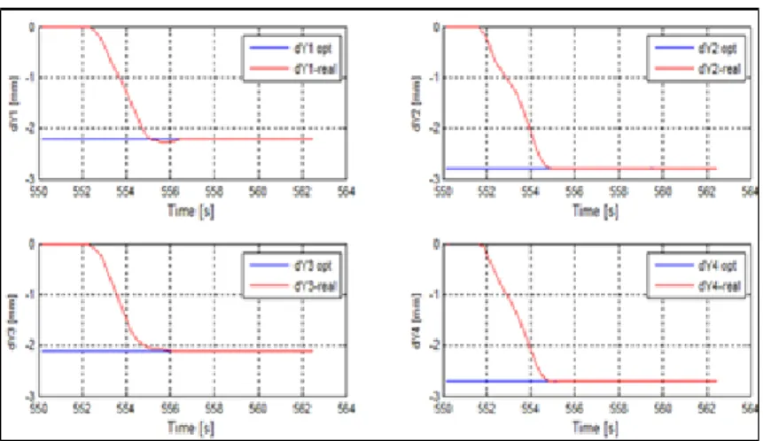
dYopt desired vertical displacements of the optimized airfoil at the actuation points dYreal real vertical displacements at the actuation points
M Mach number α angle of attack
δ aileron deflection angle
a, b, c parameters of the triangular membership functions
i
a1 parameters of the linear function f (x1) A fuzzy set in the antecedent
i
A1 associated individual antecedent fuzzy sets of input variable
i
b0 scalar offsets
B friction coefficient of the load bearing
dYopt desired vertical displacements of the optimized airfoil at the actuation points dYreal real vertical displacements at the actuation points
e back EMF
f frequency f (x1) polynomial function
Ge(s) transfer function of the electrical part of the motor Gi(s) transfer function of the current controller
Gm(s) transfer function of the mechanical part of the motor Gp(s) transfer function of the position based encoder controller J inertial load of the output motor shaft
ke angular speed constant kt torque constant
Kdp derivative gain in position controller Kit integral gain in torque controller
Kpp proportional gains in position controller Kpt proportional gains in torque controller
XXXI L motor inductance M Mach number R motor resistance Te motor torque TL load torque u voltage command M Mach number α angle of attack
δ aileron deflection angle
m
ω
angular speed of the motor output shaftx independent variable on the universe of discourse x1 individual input variable
y crisp function in the consequent
i
y First-order polynomial function in the consequent
α angle of attack
δ aileron deflection angle ω pulsation
τe electrical time constant of the motor
τ constant
θ motor shaft angular position M Mach number
δ aileron deflection angle Wto Take-Off Gross Weight
INTRODUCTION
Air transport is a key factor, and one of the most used means of transportation of people and goods. In the Annual Report of Aviation Climate Solutions, it was specified that the airline industry supports the transport of close to 3.3 billion passengers annually, and an increase of 3 % is expected by 2050, which will be equivalent to around 4 billion. This increase is illustrated graphically in Figure 0.1. The growth in passenger numbers in air transportation has direct consequences from an environmental perspective.
Figure 0.1 Total regular traffic between 2002-2011 (Taken from ICAO council annual report 2011) 0.1 Environmental impact of aviation
Human actions release harmful gases to the environment from a number of different actions, including:
• Flaring (burning natural gas flares), producing electricity by burning fossil fuels or other fuel sources,
• Fires in forests during hot weather, • Large-scale livestock (methane), • Transportation (air, land, sea, etc.).
In its 2007 Report the IPCC (Intergovernmental Panel on Climate Change) estimated the amount of carbon dioxide (CO2) emitted by the aviation sector to be approximately 2% of the
total CO2 emitted annually. In the same report, the IPCC states that this amount will increase up to 3% in 2050.
0.2 Technological advancement
With the goal of preserving a healthy environment for future generations, a number of governments, in collaboration with industrial partners, research centers, and universities meet in numerous seminars and conferences to find new solutions or to enhance existing solutions, and to set common objectives for short, medium and long term research in these areas.
The development or improvement of technology in the previous decades has also benefited the aviation sector by allowing the aviation industry to save up to 35% in terms of fuel consumption reduction according to The IATA Technology Roadmap Report issued in June 2009. The study conducted between 1990 and 2008 showed a reduction of about 4.1 billion tons of CO2, and thus a significant drop in fuels burnt, as reported in IATA Technology Roadmap 4th Edition in June 2013.
The IATA Technology Roadmap Report presented an estimated time frame for technological progress, and the different methods of fuel consumption reduction for the aviation sector. In the same report, the fuel reduction percentage estimation was presented for each technology. Table 0.1 shows the estimated fuel economy for the following technologies: Natural Laminar Flow, Advanced Fly-by-Wire, Electric Airplanes, and Morphing Material.
Table 0.1:Technology available for new aircraft designed before 2020 (Adapted from IATA Technology Roadmap, issued in June 2009)
Technologies Fuel reduction
Laminar Natural Flow 5-10%
Advanced Fly-by-wire 1-3%
Morphing material 1-5%
The technologies presented in Table 0.1 were selected due to their similarities with the technologies presented in this thesis. The report recommended by IATA estimated that for a
3
passenger aircraft with 120 seats, and a takeoff weight of 60,000 kg, a full tank containing 24,000 liters would give a saving of 1% fuel (240 liters or 200 kg). The CO2 reduction would offer significant financial savings over the long term.
In association with aircraft manufacturers and aviation service providers, IATA has fixed two main objectives: Reducing by 1.5% per year the amount of CO2 starting from 2009 and continuing to 2020, and Halving the CO2 amount for 2050 horizon from its 2005 level.
0.3 Morphing Potential Benefits
The “morphing wing” concept can be understood as the ability of a wing to change its initial shape in real time depending of the flight conditions. The targeted objective for using the morphing wing concept is to increase its aerodynamic performance.
The conventional aircraft wings are designed to be efficient during cruise. They are equipped with different control surfaces such as slats, flaps, spoilers and ailerons. These control surfaces are not considered as integral parts of the wing. They are attached to the wing with hinges; these hinges actually create discontinuities, and lower the aerodynamic efficiency of the wing because they induce turbulence in the air flow over the wing.
Morphing wings concepts require generally actuators or actuation mechanisms, sensors and a flexible skin. The power of the actuator, its force, weight, volume and size are important parameters to take into account in the wing design phase. The actuators not only support a structural load, but also an aerodynamic load, which is why they have to be self-locking. Using the morphing concept, classical geometry-variation control surfaces (slats, flaps and ailerons) could be replaced by a flexible structure, an integral part of the wing, capable of producing a smooth variation of the wing’s geometry. The morphing wing technique might give benefits in terms of significant drag reduction.
Studies realized at NASA (Sridhar, Osborn et al.) evaluated the saving cost for the U.S fleet of wide-body transport aircraft to be 140 million USD for a drag reduction of more than 1%. The amount of fuel cost saving is dependent of course on the flight distance.
0.4 Presentation of the CRIAQ MDO 505 project
Reduction of carbon emissions is one of the most important subjects, and is approached from different sectors. Each sector is required to find its appropriate technological solutions. In the aeronautical field, different paths could be followed to achieve the common goal of reducing fuel consumption:
• More efficient propulsion systems,
• Integration of light weight materials in aircraft manufacturing, • Improved aircraft flight trajectories.
According to the classification proposed in the IATA report, some of these technologies need to be integrated into future aircraft. This integration becomes a great challenge for airplane manufacturers as they face issues of compatibility, reliability, profitability and certification for their systems. The ideal consensus for solving these problems is the manufacturing of a large-scale prototype, which can be tested and validated by experimental wind tunnel testing and further by flight tests. Thus, the CRIAQ MDO505 project was launched in 2012 and brought together students, researchers, and industrial experts to achieve the common goal of reducing aircraft fuel consumption by reducing its drag through an active morphing structure. Drag reduction was further validated experimentally by wind tunnel tests. The wing drag reduction was achieved by moving the laminar/turbulent flow transition region towards the wing trailing edge. The delaying of the flow transition allowed to obtain an extended laminar flow on the upper surface. Changes of the configuration of the wing airfoil had effects on the lift, and drag loads, as well as on the flow transition region. The turbulent flow was minimized as much as possible, thus less drag, and fuel consumption are obtained.
The CRIAQ MDO505 project was funded by both government and industry. The Canadian participating industrial companies were Bombardier Aerospace, Thales Canada, and the Canadian Research Institute IRA-NRC. This multidisciplinary project was international as it took place in collaboration with Italy. The Italian partners were Alenia, University of Naples and CIRA. The multidisciplinary aspect of this project was marked at the academic level in Canada by the collaboration between different teams at the ÉTS in Controls, Aerodynamics, Structures and AeroServoElasticity areas, and at the École Polytechnique in Montreal. The
5
flow diagram shown in figure 0.2 represents the contributions of all partners. The Italian team specific contribution was to design, manufacture and control a morphing aileron to increase its lift. The Italian team contributions are not included in this flow diagram.
Figure 0.2 Simplified flow diagram
The respective tasks were assigned to different teams early in the project, and are detailed forthwith. The structural team at the ETS and at the IAR-NRC were in charge of designing and manufacturing the wing and the rigid aileron. The LARCASE team, lead by Dr. Botez, the project leader, was in charge of the design and implementation of the control laws in open and closed loop, and of developing and conducting the aerodynamic studies for the characterisation and calibration of the pressure sensors installed on the morphing area of the wing upper surface. Aerodynamic studies were carried out at LARCASE to determine the desired aerodynamic airfoils shapes and the required displacements to be implemented by the actuators for the flight conditions for the experimental wind tunnel test; the team of IRA-NRC team was in charge of coordinating the wind tunnel tests at their wind tunnel facility, of
performing infrared measurements and loads measurements by use of their balance (‘’weighting system’’). The tasks assigned to the Italian team were similar to those of the Canadian team, but they were applied to the morphing aileron. These tasks concerned the design, manufacturing and control of the morphing aileron.
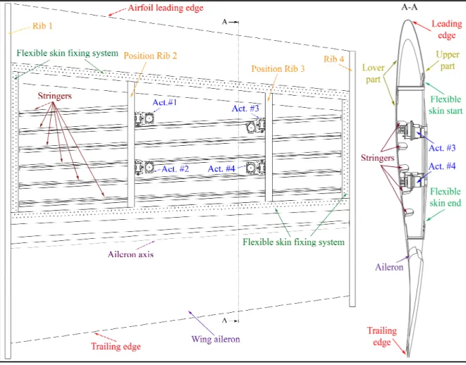
For this project, an industrial trapezoidal wing demonstrator with a root chord of 1.5 m, a span of 1.5 m and a leading edge sweep angle of 8 degrees was designed and manufactured. It was also equipped of ribs and spars, two actuation lines located at 32% and 48% of the chord, respectively, and a trailing edge on which a morphing or rigid aileron was attached. The ailerons hinge is located at 72% of the chord. The rigid inner part of the wing is manufactured essentially of aluminum, while a portion of the wing upper surface between 20% and 65% of the chord is made of a flexible skin. This flexible skin has been optimized, and was manufactured essentially of composite materials by the structures team at the ÉTS. It has been optimized to withstand structural tensile, compressive forces, and aerodynamic loads in the IAR-NRC wind tunnel. Thus, aero-structural research was carried out. Bench tests were also performed for 1 g loads in the absence of aerodynamic loads following Bombardier team requirements. Three sets of tests were conducted on the demonstrator at the IAR-NRC subsonic wind tunnel in Ottawa.
0.5 Overview of the subsonic wind tunnel where the tests were performed
The IAR-NRC wind tunnel is a closed circuit subsonic wind tunnel whose maximum speed is 140 m /s. The chamber of the test section measures 1.9 m x 2.7 m x 5.2 m (width x height x length). The turbulence rate was fixed at 0.14%. It is equipped with a cooling flow system during testing, which has a data acquisition and control system. This facility is also leased by other industrial and university partners.
The IAR-NRC wind tunnel is provided with a weighting system (balance) to measure all the aerodynamic forces and moments acting on the model installed in its test chamber. Thanks to the pressure taps installed in the test chamber, its static pressure can be measured. The information given in this subsection is provided by the website of the IRA-NRC (www.nrc-cnrc.gc.ca).
7
0.6 Objectives and originality of the controller
The global goal of the project is to extend the laminarity area over the upper surface of the wing. The extension of the flow laminarity is accomplished by changing the flexible skin shape of the wing upper surface. Actuators used for the wing upper surface shape change are controlled to maintain its desired shape position for any given flight condition.
To achieve the global objective of the project, the research work presented in this thesis is aimed to design and test a real time controller of the actuator displacements under any flight conditions. The actuators fixed on the ribs have to provide the necessary force to push/to pull on the skin and modify its aerodynamic airfoil shape that will be optimized for increase of aerodynamic performance of the wing. Different control laws were designed and experimentally validated in the IAR-NRC wind tunnel on the morphing wing.
The originality of the thesis consists in the numerical and experimental control of in-house electrical actuators used to change the morphing wing airfoil shape by use of different control methodologies. Two types of ailerons (conventional and morphing) were attached to the wing during three sets of wind tunnel tests. A set of thirty-two Kulite pressure sensors were integrated on the upper surface of the morphing wing to acquire the pressure fluctuation over the wing. Besides, the final adopted control architecture took into account the dynamic of the actuator’s motor voltage amplifier. The objective is not only to compensate actuator’s backlash, but also to synchronise both position sensors (“encoder” measuring the motor’s shaft position and linear “position sensor” measuring the morphing skin displacement). 0.7 Issues of the research
The main challenge of the global project is to design and manufacture a reliable active demonstrator that fulfills the desired requirements: the aerodynamic efficiency (drag reduction, laminar flow extension or improvement) of the morphing wing should be improved.
The operating control system of the actuators used in the research project was entirely designed and manufactured at the ÉTS and is presented in this thesis. The development of a
control law for such an actuator control system with a precision of +/- 0.1 mm was in itself a significant challenge due to the presence of plays accumulated in the system after its assembly.
Regarding the system calibration there was a need to verify that the morphing skin moved exactly with the requested displacements set point. The dial indicators were installed outside the wing, as illustrated in Figure 0.3. Collected values of dial indicators, linear position sensors and skin set point requested or desired over time have shown that due to the flexibility of the entire system, dial indicators and linear position sensors values were different. The calibration of the system for each flight case by adjusting the linear position sensor set point was performed to overcome these issues. Another challenge constraint was the dedicated space available for the actuator’s installation inside the wing.
9
0.8 Contributions
The main contributions in this thesis were mainly in the: • Actuator Model Design,
• Control Schematics Architecture Experimental Validation during the bench tests at the ÉTS and during the wind tunnel tests at the IAR-NRC and at the LARCASE (Price-Païdoussis wind tunnel),
• Graphical User Interface (GUI) Programming to control the entire system, and
• System Integration to ensure the interaction between different software and hardware (control, communication, database) for wing and aileron.
Different methods were used to realize each step of these contributions. The actuator designed used in the thesis consisted essentially of two components: one electrical and one mechanical. The electrical component consisted in a motor with a gearbox, while the mechanical component included a gearing system, screw and nut. For the actuator model design, its electrical component was firstly designed, and secondly its mechanical component was added.
Figure 0.4 Equivalent model of the actuator’s motor and its Load
A brushless direct current motor was used in the actuator. This kind of motor has no brush and the commutation occurs through electronic commutation occurs. This definition is often referred in the literature as ‘’Electronically Commutated Motor’’. The commutation board is made of a transistor or a Thyristor Bridge. The current flow through the switches is controlled by the digital output (0 or 1) of hall sensors fixed on the motor stator. The motor’s rotor position is sensed by hall sensors.
Brushless direct current motors have the same behaviour as a direct current motor when two motor phases are conducting. Therefore, this motor can be modeled as a direct current machine having the equivalent circuit shown in Figure 0.4. The equations of the circuit shown in Figure 0.4 are the following:
(0.1)
(0.2)
where is the total system (motor and load) inertia, is the motor friction, is the motor’s mechanical speed, is motor’s winding resistor, is the motor’s winding inductance, .is the electromotive force. The Laplace transformations of equations (0.1) and (0.2) can be expressed as follows:
(0.3)
(0.4)
Then, the block diagram is obtained in the Laplace domain and is further shown in Figure 0.5. The steps used to obtain this block diagram are explained in details in the articles
( ) ( ) ( ) -eq m e L J
ω
t + Bω
t =T
tT
( ) ( ) d i ( ) u t R i t L e t d t = + + eqJ
B ω R L e ( ) ( ) ( ) -eq m e L Jω
s + Bω
s =T
sT
( )
( )
( )
( )
U s
=
RI s
+
LsI s
+
E s
11
inserted in this thesis. The load torque given in equation (0.1) is neglected in order to simplify the control design.
Figure 0.5 Motor block diagram
Equations (0.1) to (0.2) are used mainly to obtain the linear model of the actuator. This model is validated based on a comparison between the static values obtained in the simulation and those given by the datasheet of the manufacturer.
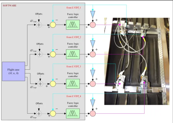
Different methodologies were developed in Matlab/Simulink to control the actuator, but not all of them were validated in both bench and wind tunnel tests. As mentioned above, because of the fact that the motor of the actuator is a brushless DC motor, it is equipped with a hall sensor that senses the rotor position. The motor position sensor is not enough to use as feedback signal for the position control for the skin displacement with the presence of plays inside the actuator. For this reason, Linear Variable Differential Transducer (LVDT) is coupled with the actuator to sense the skin displacement, and to reduce the influence of the plays.
A cascade structure with three different loops is chosen to be implemented as control architecture. The three distinct loops are: the innermost loop (first loop), that is the torque loop followed by the position controller (second loop) based on a hall sensor. Because of the fact that an accurate control position of the skin is needed, the outermost position (third loop) loop based on the LVDT is superposed on the hall sensor position loop
The controllers designed in this thesis are: a Proportional Integral (PI) controller for torque control, a Proportional Derivative for position control based on an encoder and two different Fuzzy Controllers for Position control based on Linear Variable Differential Transducer. Fuzzy controllers are non-linear and, they were developed firstly in 1974. They are called ”rule-based” controllers in the literature, because this control strategy describes a control protocol by means of rules. The rules describe the system behaviour observed by the machine operator. With the increase in the power of processors, this kind of controller is now being used in of different domains such as automotive, robotics and transportation. Fuzzy controllers consist of a Fuzzifier, an Inference system or a knowledge based system, and a Defuzzier. The Fuzzifier converts the crisp values (controller input) in its corresponding membership grade in the antecedent fuzzy sets. A Fuzzy set is composed by elements that are linguistic variables or linguistic terms. The output of the Fuzzifier uses rules stored in the knowledge based system to calculate the necessary input value for the Defuzzifier. The Defuzzifier’s role remains converting the fuzzified values into a crisp signal or into process values, as shown in Figure 0.6.
Figure 0.6 Fuzzy Controller Components
In general, for a fuzzy control it is recommended to consider with three linguistic terms for each of its fuzzy inputs. The corresponding number of linguistic variables for the output is given by , where X is the number of membership function of the input variables. For the Proportional Derivative Fuzzy Controller, the interval considered for the error, and the error rate is [-12, 12] as shown in Figure 0.7, while the fuzzy rule is shown in Table 0.2. The linguistic terms for the inputs are: Negative Large (NL), Negative (N), Zero (Z), Positive (P) and Positive Large (PL).
2X −1
Crisp values
13
Figure 0.7 Error Membership Functions
Table 0.2 Fuzzy rules table
Error rate Error
Negative
Lage Negative Zero Positive Positive Lage
Negative Lage
Positive very
large Positive large
Positive
medium Positive small Zero
Negative Positive large
Positive medium
Positive
small Zero Negative small
Zero
Positive
medium Positive small Zero
Negative
small Negative medium
Positive Positive small Zero
Negative small
Negative
medium Negative large
Positive Lage Zero Negative small Negative medium Negative
large Negative very large
The control surface shown in Figure 0.8 was generated after fixing the Fuzzy rules. The system behaviour constrained the controller to produce a linear shape. Because of its lower rise and settling time, as illustrated in Figure 0.9, compared to the Proportional Fuzzy Controller, only the latter Fuzzy logic control was validated experimentally in the wind tunnel.
Figure 0.8.Control surface for the PD-Fuzzy control
Figure 0.9 Comparison of PD- and P-Fuzzy control
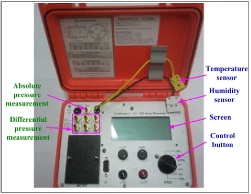
Differential pressure sensors were used to measure the pressures on the wing upper surface. Some of the attractive properties of these pressure sensors are their light weight (0.2 g), their robustness in electromagnetic fields, and their amplified output signals with high precision (±0.5% of maximum measurement range) and resolution (0.1 Pounds per square inch (PSI)). The aim of these sensors is to identify the presence of the Tollmien-Schlichting waves in the flow that characterizes the laminar-to-turbulent flow transition. The piezoelectricity principle
15
is used in manufacturing these sensors and in the generation of an electrical signal at the output of the piezoelectric material when a mechanical effort is applied to it. The measurement range of the selected pressure measurement for transition is 5 PSI. This limit was chosen following aerodynamic calculations, where the maximum pressure was found to be for a morphing wing less than 5 PSI. The natural oscillation frequency is 150 kHz and the signal bandwith is 20 kHz. The characterization of the piezoelectric Kulite pressure sensors was realized by Manuel Flores Salinas.
Flutter analyses were performed by the aerodynamic team to ensure that no critical frequencies could appear during wind tunnel testing. To monitor the different frequencies when the wind was blowing, two accelerometers (one installed on the wing tips, and the other installed within the rigid aileron) were used. The program used to post-process the sensor data was written in Labview with the aid of Master students Vincent Rault and Yvan Tondji.
Following the introduction, the contributions, a literature review will be presented, that will show the evolution of the concept of the morphing wing in time. The literature review will be followed by published and submitted articles, written during this thesis. This thesis ends with a conclusion and recommendation for future work.
Chapter 2: Literature review.
This chapter presents a review of the state of the art in this field. An evolution of the morphing wing technology, description of actuators used for wing deformation, control strategies and materials used by various authors for morphing wing.
Chapter 3: Article 1.
Before the official start of the CRIAQ MDO505 project, another morphing wing type project has been initiated at the LARCASE laboratory. One of its objectives was to prepare and familiarize students with the following subjects for the CRIAQ MDO505 project:
• Morphing wing design, • Theory of control logic, • Actuator theory,
• Controller design, implementation and validation, • Wind tunnel calibration,
• Data processing.
For this project, after manufacturing the test wing model, and after conducting wind tunnel calibration, the designed controller for the actuator was tested in the Price-Païdoussis subsonic wind tunnel located at ETS LARCASE in Montreal.
Chapter 4: Article 2
This paper presents the model of the actuator and its control methodology for the CRIAQ MDO505 project. In parallel, an experimental bench test was manufactured, and further used to validate the experimental controller. The experimental control was designed to be used in wind tunnel facility. The experimental results showing the controller’s functionality were demonstrated. During the bench tests at the LARCASE no aerodynamic load was applied on the skin. The structure of control validated on the bench at LARCASE is illustrated in Figure 0.10. Due to the system repeatability the offsets values are determined to compensate the permanent static error. The offset values are not the same for all flight cases. The LVDT values are added to the controller’s output in order to maintain the reference values (pink color in Figure 0.10) constant for the control architecture within the motor voltage amplifier.
17
Figure 0. 10 Control architecture on bench test at LARCASE Chapter 5: Article 3
This paper explains the experimental results of the controller in terms of infrared measurements obtained at the IAR-NRC wind tunnel facility. Aerodynamic loads were applied on the model in this context. Thirty eight flight cases were tested. The Mach number varies between 0.15 to 0.25, angle of attack from -3 to +3 degrees, and aileron angle deflection from -6 to +6 degrees.
Chapter 6: Article 4
Article 4 focuses on the design of the linear model and its control. The proposed model represents the exact architecture, also as well as the simplified architecture of the control software tested in wind tunnel. The validation of the actuator numerical model was carried out by comparing numerical with experimental data. Besides, further wind tunnel results in terms of infrared measurements are shown.
Chapter 7 Article 5
The reasons for developing a parallel control system for position control were illustrated. The methodology used to post-process the wind tunnel acquired data was explained and comparisons in term of transition point position detected between pressure sensor and infrared tests were pointed out.
CHAPTER 1
RESEARCH APPROACH AND THESIS ORGANIZATION 1.1 Thesis research approach
In this thesis, research was performed in two multidisciplinary projets at the LARCASE, called ‘’ATR-42 morphing wing’’ and ‘’ MDO505’’. The thesis concentrates on the research done by the control team in the frame of these multidisciplinary aero-structure-control projects.
The global objective of the research in the frame of the CRIAQ MDO505 project, is to enhance aerodynamic performances by controlling the wing shape in real time according to flight conditions, and it achieved by division of the research into 5 phases:
• Determining the most suitable actuator and actuation mechanism for the morphing wing; • Actuator and its controller design,
• System integration and calibration,
• Controller validation on the bench test with no aerodynamic load; and • Controller validation in a wind tunnel.
Before the official start of the CRIAQ MDO505 project, the ”ATR-42 morphing wing” project, on the realization of the adaptive upper surface morphing concept for the ATR-42 wing , was initiated at the LARCASE in 2011.
In both multidisciplinary projects work was performed on the controller in collaboration with aerodynamics and structural teams. In both projects, in which the aerodynamic studies were performed firstly by the aerodynamic team to determine the optimal wing shape configuration and the actuator displacements. In parallel to the aerodynamic optimization, an aero-structural optimization method was developed. The goal of this optimization procedure was to reduce the composite skin weight while ensuring a good approximation of the targeted aerodynamic shapes. The skin optimization process aimed to respect the industrial partners’
requirements. Analytical validation methods used to test the structural integration were able to determine the stiffness, the bucking and strength of the morphing wing.
The CRIAQ MDO505 project is essentially a continuation of the ATR-42 and CRIAQ 7.1 projects, focusing on extending the laminarity over a flexible wing upper surface where an actuation mechanism combined with four actuators are integrated inside the wing. To determine the actuator for the MDO 505 project feasibility studies and constraints analyses were performed by the structural team. The constraints analysis made it possible to determine the minimal height of the actuator to best fit inside the wing. The minimal height is the smallest distance between the inner and upper surfaces. The required actuator force was evaluated by the structural team during its static linear analyses with HyperMesh. Adding a security factor of 1.5 the value of 1500N was established. Studies were done by LARCASE and the structural team to select the best motor and gearbox for the actuator, that were designed and manufactured by David Barry (Master student). Figure 1.1 shows the actuator assembled with no Linear Variable Differential Transducer (LVDT).
Figure 1.1 Manufactured in-house actuator
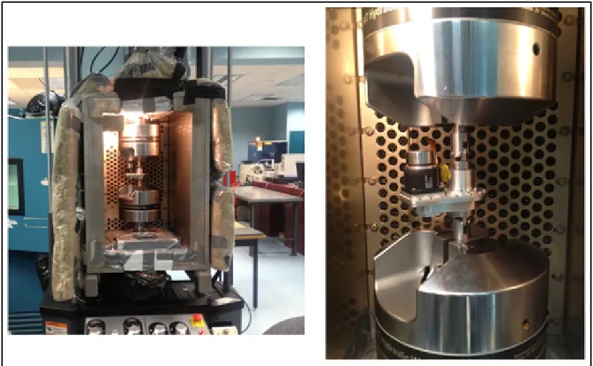
Subsequently, the capacity of the actuator to support at least the maximum load was validated in a traction/compression test apparatus at ETS as illustrated in figure 1.2.
21
Figure 1.2 Actuator during robustness test at the ETS
To validate our actuator’s performance, a series of four tests were conducted, and an automatic cyclic program to move the actuator between +/- 3 mm was coded in Labview. During the first series of tests, the machine pulled on the actuation moving at 16% of its nominal speed with a force from 750 N to 1500 N. Wear has been observed inside the screw, but the actuator resisted well to the applied load. These results proved the robustness of the actuator and its ability to be integrated inside the wing in order to obtain aerodynamic optimized shapes for each flight case.
In a first approach, a nonlinear numerical model (due to the shape of the back emf) of the actuator, and its control were realized, based mainly on the data provided by the manufacturer in the datasheet. This approach was not validated experimentally because the annual licence cost for the software to use in conjunction with the corresponding hardware was too high and we couldn’t buy it. This approach would have offered a very good algorithm validation with the dedicated hardware. But after some experimentation it was observed that much time would be required to replace the shipped BLDC motor with one of
the morphing actuator and to write the necessary code. Additionally it was required also to develop LVDT interface and necessary code for data acquisition.
In a second approach, a linear model of the actuator and its control was developed. Different control logic concepts were tested, and further validated experimentally on a bench test in the absence of wind, and in a wind tunnel. The disadvantage of this approach resides in the consideration of constraints on designing a linear control imposed by the hardware (motor’s voltage amplifier). A configurable linear cascade control architecture (controller’s gains could be changed) was implanted by the hardware (motor’s voltage amplifier) provider. This architecture made it possible for different existing linear methods such as Bode diagram, Ziegler Nichols, and pole cancellation to be adapted for the morphing wing application. These methods were further utilized to obtain the appropriate gains for the controllers. The following parameters were assumed for the control modeling:
• Maximum steady state error of 0.1 mm, • Rise time between 1 and 2 seconds), • No load disturbance,
• Unity feedback, and
• Total inertia that consists in the sum of motor and gearbox inertia.
The software and hardware integration was carried out at the LARCASE. A number of different functions were developed and compiled, and a large amount of code was generated for the software integration. Subsequently, the compiled functions were deployed into the real time target. A total of 5 different codes were generated, and linked with each other. Bench tests in the absence of winds, at the LARCASE, and wind tunnel tests were conducted to verify the controller’s performance, to assess the system and software integration, and to test the system’s response in the extreme conditions. The wind tunnel tests took place in the Price-Païdoussis wind tunnel at the LARCASE ETS in the frame of the ‘’ATR-42 morphing wing’’, and in the IAR-NRC wind tunnel in Ottawa.
23
1.2 Thesis Organization
Several journal articles and conference papers are published, accepted for publication, and under review based on the methodologies and results obtained in the bench and wind tunnel tests and simulations. Five articles were submitted in peer-review journals. Two of the journal articles have been published, and three other articles are under review. Chapters 3 to 7 each present one of these journal articles.
Dr. Ruxandra Mihaela Botez, as co-author of all journal and conference papers supervised the progress and the realization of the research. In all five papers, co-author Lucian Grigorie contributed with his experience acquired in the previous CRIAQ 7.1 project as postdoctoral fellow in terms of constructive discussions on control issues. In chapter 3, co-author Andreea Koreanschi PhD student created the aerodynamic shapes with the corresponding actuator displacements by use of XFoil code. In Chapters 6 and 7, co-authors Mahmoud Mamou and Youssef Mébarki from IAR_NRC coordinated the interactions between all teams during the wind tunnel tests, and they also performed and post-processed the infrared and load (lift, drag. moments) measurements. Co-author Yvan Tondji (Master student) assisted in the pressure sensor data (Kulite) post-processing and in its interpretation, by using its in-house software coded with Matlab/Simlink. On paper (see section 2.2.1) was published on the ATR-42 project, and the other four papers were published on the CRIAQ MDO505 project. 1.2.1 First journal paper “Design and Wind Tunnel Experimental Validation of a
Controlled New Rotary Actuation System for a Morphing Wing Application” Presented in Chapter 3 and published in the Proceedings of the Institution of Mechanical Engineers Part G Journal of Aerospace Engineering, this paper concentrates on the design and implementation of a controller for a rotary actuator, and its experimental validation on a morphing ATR-42 wing. The comparison between the numerical pressures calculated by the 2D solver XFoil, and the experimental pressures is also performed.
In this paper, the model of the actuator was considered to be linear with the aim to simplify the design of the controllers. A cascade loop was designed, and further implemented. The torque loop is followed by the position control loop. Current controller gains were obtained
with the Bode diagram method, while Ziegler-Nichols method was used to compute the position controller gains. The relationship between the actuator’s displacement in degrees and the vertical displacement in millimeters was measured with a Coordinate Measuring Machine (CMM) at ÉTS. Pressure taps installed on the wing were used to measure the static pressures over the wing, while the wind tunnel static pressure was measured with a Pitot tube. The pressure taps were connected to a signal processing unit which displayed the pressure values, and the pressure coefficient values were using Excel. Experimental results were presented Mach number equal to 0.2 and for different angles of attack between -1 and 1 degree.
1.2.2 Second journal paper “Design, numerical simulation and experimental testing of a controlled electrical actuation system in a real aircraft morphing wing model”
Inserted in Chapter 4 of this thesis, this paper was published in the Aeronautical Journal on September 2015. It explained a nonlinear model of the actuator and its control that was not validated on a bench test. It presented also the experimental bench test results in the absence of winds by using the non-linear model of the controller that was turned essentially based on the system’s behaviour. Thirty-eight flight cases were tested and for each flight an offset was obtained and used to modulate the requested actuator position. The offset values were permanently the same due to the system’s repeatability. The modulation purpose of the requested set points was to eliminate the static error for each flight case. This approach was improved later by considering the encoder signal in the control.
1.2.2 Third journal paper “Experimental Validation of a Morphing Wing Control System in Open Loop”
Presented in Chapter 5, this paper has been submitted to the Chinese Journal of Aeronautics and is currently under review. For the first series of wind tunnel tests, a number of 38 flight cases were tested. The real time system was installed on the wind tunnel balance which was connected with the morphing wing demonstrator. This journal paper presents essentially the results obtained during the first wind tunnel tests. The results were expressed in terms of Fast Fourier Transformation (FFT) and Root Mean Square (RMS) for the pressure sensors, and
25
infrared measurements. In general, it has been observed that the flow as laminar flow extended closer to the trailing edge. Based on the observations during the first set of wind tunnel tests, it was recommended that for the second series of wind tunnel tests, the extension of the infrared recording time for each flight case (flow stabilization) and the increase of the number of flight cases tests.
1.2.3 Fourth journal paper “Control of the morphing actuation mechanism integrated in a full-scaled portion of an aircraft wing”
Presented in Chapter 6, this paper has been submitted to the Aerospace Science and Technology, and is currently under review. In the second paper journal (Chapter 4), a nonlinear model of the actuator was shown, which was not validated experimentally because of the expensive license cost and additional work to accomplish on the dedicated hardware (CM408F DSP). To address these lacunae, the fourth paper proposes a linear model of the actuator with its control. The control architecture (triple loops) represents exactly the architecture used in the wind tunnel. The model has been validated experimentally on a bench test with the dedicated hardware. Wind tunnel results for the second test series are presented, for the suggestions after the first wind tunnel test were taken into account. A slight improvement in terms of infrared measurement results was observed. For the second series of wind tunnel tests for the flight case 68, pressure sensors revealed a transition delayed of 9 % of the chord. The transition for the non-morphed case was detected at 44% of the chord and at 53 % of the chord.
1.2.4 Fifth journal paper “Morphing wing demonstrator tested in a subsonic wind tunnel in open loop configuration”
Presented in Chapter 7, this paper has been submitted to the Aerospace Science and Technology, and is currently under review. In the control architecture presented in the fourth article (chapter 6), two loops were focused on position control by use of an encoder and a LVDT. This paper denotes in details the reasons that led to the development of two position loops instead of a speed and position loop as it was implemented in conventional motor drives. LVDT was selected as a solution to measure the skin displacement and to compensate backlash (play) inside the actuation. The post-processing of the pressure sensors data
collected during was done with software developed at the LARCASE. The details regarding the software code were explained in details in this article and infrared measurements for the second set of flight cases have been also presented. For the second series of wind tunnel tests for the flight case 70, pressure sensors revealed a transition delayed of 8 % of the chord. The transition for the non-morphed case was detected at 43% of the chord and at 51 % of the chord.