HAL Id: pastel-00765635
https://pastel.archives-ouvertes.fr/pastel-00765635
Submitted on 15 Dec 2012
HAL is a multi-disciplinary open access
archive for the deposit and dissemination of sci-entific research documents, whether they are pub-lished or not. The documents may come from teaching and research institutions in France or abroad, or from public or private research centers.
L’archive ouverte pluridisciplinaire HAL, est destinée au dépôt et à la diffusion de documents scientifiques de niveau recherche, publiés ou non, émanant des établissements d’enseignement et de recherche français ou étrangers, des laboratoires publics ou privés.
microflows
Hélène Berthet
To cite this version:
Hélène Berthet. Single and collective fiber dynamics in confined microflows. Fluid Dynamics [physics.flu-dyn]. Université Pierre et Marie Curie - Paris VI, 2012. English. �pastel-00765635�
UNIVERSITÉ PIERRE ET MARIE CURIE (Paris 6)
ÉCOLE DOCTORALE 389
LA PHYSIQUE, DE LA PARTICULE À LA MATIÈRE CONDENSÉE
THÈSE DE DOCTORAT PHYSIQUE DES FLUIDES
H
ÉLÈNEB
ERTHETS
INGLE AND COLLECTIVE FIBER DYNAMICS IN
CONFINED MICROFLOWS
Soutenue le 9 mars 2012
JURY
Mme Isabelle Cantat Rapportrice
M. Eric Climent Rapporteur
Mme Elisabeth Guazzelli Examinatrice
Mme Elise Lorenceau Examinatrice
M. Harold Auradou Examinateur
M. Alfred Crosby Examinateur
Mme Anke Lindner Directrice de Thèse
THÈSE EFFECTUÉE CONJOINTEMENT AU
L
ABORATOIRE DE
P
HYSIQUE ET
M
ÉCANIQUE DES
M
ILIEUX
H
ÉTÉROGÈNES
(PMMH)
UMR CNRS 7636
École Supérieure de Physique et de Chimie Industrielles de la Ville de Paris (ESPCI)
10, rue Vauquelin 75231 Paris Cedex 05
ET
É
TUDES ET
P
RODUCTIONS
SCHLUMBERGER
W
ELL
S
ERVICES
I
NTEGRITY
1 rue Henri Becquerel 92140 Clamart, France
M
ERCI
I am very grateful to Anke Lindner, my supervisor and guidance along these three years, for believing in the experiments and pushing me towards the first results, and for her always pertinent advice. It was a truly scientifically-enriching adventure in a positive, open-minded environment. Thank you!
I would also like to express my gratitude to Schlumberger for supporting my PhD, in partic-ular Gerard, Jean, Jean-Philippe, Paul, Benoit, Bernard for their scientific support. I thank WIT for understanding the fundamental aspects of my research and balancing them with the industry-side challenges and fast responses which are their everyday jobs.
Thank you Katia, Eve, Amandine, Tullio, for the great fun, encouragements and help in the "and now, what?" question.
Thank you Michael for your support. Cambridge has been a big part of this work.
A lot of thanks to the PMMH lab, in particular: Olivia for her huge help with the experiments; Marc for his scientific guidance, for launching the simulation side of my work and help me in making it a significant part; Julien; Fabrice, Hervé from MMN. Thank you Yoann, Dylan and Pierre who interned with me at the lab, for their hard work and good company. Thank you Sophie for lending me some of your CPU, many results in this manuscript would not have seen the light of day without your super-powerful computer!
Merci to Nawal, Sophie, Cathy, Nais for the best office of pmmh, to my dear Frederique and Amina for the other best office in pmmh, for the morning hello and so nice "thé à la menthe toutes ensembles". Merci to Anne, Denis, Ramiro, José, Pierre-Brice, Olivier, Thibaut, Alain, Chelsea, Baptiste, Jeremie, Etienne, Patrice, Evelyne, Bertrand , Gaston, Khanh-Dang, Annie, Eduardo, Joseph, Raphaele, Dan, Caroline et Philippe.
Merci beaucoup to Marc Schneider for our Parisian and Clamartisian discussions and for your support.
Thank you Nais for your drawing for the PhD cover. It is perfect, and keeps on reminding me I have a pile of post-it notes with dinosaurs in my drawer.
Shoukran Claudio for your Egyptian painting. A memory that a lot of this manuscript was written in Egypt, and for the best reason possible. Thank you also for your help with the data processing, for your enthusiasm for the little fiber and the long hours at the lab when it seemed writing would never end.
Thank you Lionel and Claudio for reading the manuscript and providing insightful comments. And thank you to my family and numerous friends for being there, every step of the way.
R
ÉSUMÉ
Cette thèse porte sur le transport de fibres isolées et de suspensions de fibres dans des géométries microfluidiques. L’utilisation de fibres dans les fluides de forage et ciments pour réduire les pertes de circulation dans les puits de pétrole est à l’origine de cette collaboration entre Schlumberger et l’ESPCI-PMMH. Dans ce contexte industriel où les fibres en écoulement interagissent avec les roches frontières du puits et des fractures, il est nécessaire de compren-dre le rôle de la géometrie des fibres, leurs propriétés mécaniques et leur concentration, ainsi que la géométrie d’écoulement.
Nous avons créé un système microfluidique modèle qui intègre dans la même expérience la fabrication et la mise en écoulement de fibres, implémentant deux techniques différentes. Ce système nous permet d’étudier indépendamment l’effet de tous les paramètres d’écoulement. Nous proposons une méthode de mesure in situ des propriétés mécaniques des fibres. Nous étudions expérimentalement et numériquement le transport de fibres isolées dans un écoule-ment de Darcy, en fonction de l’orientation et du confineécoule-ment de la fibre. Lorsque la largeur du canal microfluidique diminue, des interactions entre la fibre et les bords latéraux du canal apparaissent. Elles mènent à un mouvement oscillatoire et régulier de la fibre entre les bords dont nous étudions la dynamique. Nous nous intéressons enfin aux effets collectifs de fibres en suspensions qui s’écoulent à travers une restriction. Nous étudions en particulier le rôle joué par leur orientation sur le blocage des restrictions, et la formation de flocs en amont de celles-ci.
MOTS-CLÉS
FIBRES,MICROFLUIDIQUE,MICROFABRICATION,ÉCOULEMENTS VISQUEUX, HELE-SHAW,EF
A
BSTRACT
In this thesis, we studied the transport of single fibers and suspensions of fibers in mi-crofluidic geometries. This collaboration work between Schlumberger and ESPCI-PMMH was motivated by the use of fibers in lost-circulation curing fluids in the oil industry. In this context where fibers are closely interacting with the flow boundaries, the roles of the geometry, flexibil-ity and concentration of fibers as well as the flow geometry need to be understood. We created a microfluidic model system, integrating in a single experiment the fabrication and the flow of tailor-made fibers, using two different techniques. This new experimental system allows us to independently investigate the effect of all flow parameters. An in situ measurement of their mechanical properties is developed. Experimental and numerical work aims at understanding the transport of an isolated fiber in the Darcy flow, depending on its orientation and confine-ment. We show that the interactions of the fiber with the lateral borders of the microfluidic channel can lead to regular oscillations of the fiber. The collective dynamics of higher concen-tration of fibers is investigated when forcing them through a restriction in the microchannel. In particular, we address the question of the role of the orientation of the fibers on the clogging of the restrictions and the formation of fiber clusters upstream of the restriction.
KEYWORDS
FIBERS,MICROFLUIDICS, MICROFABRICATION,VISCOUS FLOWS, HELE-SHAW CELL,COLLEC
C
ONTENTS
Contents 11
Introduction 15
1 State-of-the-art review 21
1.1 Flow of one fiber . . . 21
1.1.1 Slender-body theory . . . 22
1.1.2 Fiber in a simple shear flow in an unbounded medium . . . 22
1.1.3 Fiber flow near a wall . . . 23
1.1.4 Sedimentation near a wall . . . 24
1.2 Fibers in confined geometries . . . 25
1.3 Collective dynamics of fibers in suspensions . . . 27
1.4 In situ particle microfabrication techniques . . . 30
1.4.1 Lithography method of particle fabrication . . . 30
1.4.2 Self-assembling colloids to fabricate filaments . . . 32
2 Lithography fabrication of fibers 37 2.1 Fabrication principle . . . 38
2.2 Experimental protocol . . . 39
2.2.1 Experimental set-up . . . 39
2.2.2 Microfluidic channel . . . 39
2.2.3 Oligomer solutions . . . 39
2.2.4 Lithography mask design . . . 39
2.2.5 Light shutter . . . 40
2.2.6 Protocol . . . 40
2.3 Fiber characteristics . . . 42
2.3.1 Geometrical design: from the mask to the fiber . . . 42
2.3.2 Inhibition layer and consequence on the fiber geometry . . . 43
2.3.3 Enhancing the fiber surface roughness . . . 43
2.3.4 Mechanical characterization . . . 44
2.4 Fabrication and flow . . . 46
2.4.1 Fabrication with the fluid at rest . . . 46
2.4.2 Fabrication during continuous flow . . . 46
2.5 Fabrication of fibers suspensions . . . 47
2.6 Data processing . . . 48
3 Fabrication of fibers by colloids self-assembly 51
3.1 Principle of fabrication . . . 52
3.2 Experimental protocol . . . 52
3.2.1 Solution of colloids in water . . . 52
3.2.2 Microscope set-up and channel . . . 52
3.2.3 Protocol . . . 53
3.3 Fibers suspension characteristics . . . 53
3.3.1 Fiber geometry . . . 53
3.3.2 Concentration . . . 54
3.3.3 Elasticity . . . 54
4 In situ measurement of fiber mechanical properties: bending-fiber experi-ments 57 4.1 Experimental . . . 58
4.2 Numerical simulations . . . 60
4.2.1 Design . . . 60
4.2.2 Results . . . 61
4.3 Modeling in the lubrication limit . . . 62
4.4 Computation of Young’s modulus . . . 65
4.5 Conclusion . . . 66
5 Flow dynamics of a single fiber away from the lateral flow boundaries 67 5.1 Experimental results . . . 68
5.1.1 Velocity of a fiber parallel to the flow direction . . . 68
5.1.2 Effect of confinement . . . 69
5.1.3 Effect of the initial orientation . . . 70
5.1.4 Streakline visualization . . . 72
5.1.5 Conclusions of the experimental study . . . 74
5.2 Flow equations . . . 74
5.3 Numerical study . . . 76
5.3.1 2D simulation of a parallel fiber (infinite fiber length) . . . 76
5.3.2 2D simulation of a perpendicular fiber . . . 78
5.3.3 Velocity results with fiber confinement . . . 80
5.3.4 3D simulations: fiber with finite length . . . 81
5.3.5 Perturbation of the flow profiles . . . 88
5.3.6 Conclusion of the simulations . . . 92
5.4 Conclusion . . . 94
6 Single fiber interacting with the lateral flow boundaries 95 6.1 Introduction . . . 96
6.1.1 Observation of oscillating fibers . . . 96
6.1.2 Experimental set-up . . . 97
6.1.3 Regime decomposition . . . 98
6.2 Fiber in the contact phase . . . 100
6.2.1 Observations . . . 100
6.2.2 Regime characteristics . . . 101
6.3 Fiber in the rotation phase . . . 103
Contents 13
6.3.2 Angular velocity . . . 104
6.3.3 Influence of the flow velocity . . . 105
6.4 Fiber in the drift phase . . . 105
6.4.1 Drift towards a lateral wall . . . 105
6.4.2 Comparison with simulation . . . 107
6.4.3 Influence of the mean flow velocity . . . 108
6.5 Summary . . . 109
6.6 Conclusion . . . 109
7 Collective dynamics of fibers flowing through a restriction 111 7.1 Flow dynamics of dilute fiber suspensions in confined two-dimensional geometries111 7.1.1 Gallery of experimental flow configurations . . . 111
7.1.2 Protocol for the three configurations . . . 112
7.1.3 Fibers in pseudo-random initial position . . . 113
7.1.4 Fibers all parallel to the restriction . . . 113
7.1.5 Fibers perpendicular to the restriction . . . 119
7.2 Flow dynamics of a concentrated fiber suspension in three-dimensional flow ge-ometries . . . 124 7.2.1 Experimental protocol . . . 124 7.2.2 Experimental observations . . . 125 7.2.3 Image processing . . . 133 7.3 Summary . . . 133 7.4 Conclusion . . . 133 8 Conclusion 135 A Microfluidic device fabrication 139 A.1 Preparation of channel mold . . . 139
A.2 All-PDMS channels . . . 139
A.3 PDMS-glass channels . . . 140
B Simulations of a single fiber flow 141 B.1 Two-dimensional simulations in FreeFem++ . . . 141
B.1.1 Fiber parallel to the flow direction . . . 141
B.1.2 Fiber perpendicular to the flow direction . . . 145
B.2 Three-dimensional simulations in COMSOL . . . 151
B.2.1 MATLAB code for a typical flow simulation in COMSOL . . . 151
B.2.2 Determination of the fiber velocity . . . 155
B.2.3 Mesh convergence study . . . 156
C Data Processing Methods 159 C.1 Data processing for the flow experiments of single confined fibers . . . 159
C.1.1 Objectives . . . 159
C.1.2 Reference frame . . . 159
C.1.3 Enhancing the contrast . . . 161
C.1.4 Algorithm of detection . . . 163 C.2 Image processing for the experiment of fiber suspensions at high concentration . 165
C.2.1 Algorithm principles . . . 165 C.2.2 First results . . . 166
D Particle Tracking Velocimetry Methods 169
E Collaborations 173
E.1 Bending of elastic fibers in viscous flow: Jason Wexler, Princeton University . . . 173 E.2 Active suspensions: Gaston Mino, ESPCI . . . 174
I
NTRODUCTION
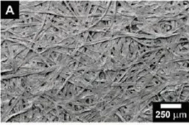
Fibers and flow of fiber suspensions have attracted the interest of physicists for many decades, motivated by several industrial applications where these suspensions are used. The oldest of them is the paper industry. Several thousand years ago, the Egyptian papyrus industry consisted in extracting stems of the papyrus plant to eventually form sheets. Paper in the form that we know today has existed since 200 B.C.: a small fragment of paper made of linen fibers was found and dated in China. Figure0.1 shows the entangled structure of fibers of a paper sheet observed with scanning electron microscopy.
Fibers have also been widely used in the oil and gas industry for applications of stimulation and lost-circulation curing [1]. Stimulating a well can be done using hydraulic fracturing: pressurized water is injected to create new flow paths for hydrocarbons. In this application, fibers are added to proppant fluid to be used as a stabilizing agent to maintain the flow channels open. In applications of lost circulation, fibers are used to seal leak paths and prevent the loss of drilling fluid and cement slurries into the rock formations. Little is known about the fractures geometry and size downhole. Therefore it remains a challenge to systematically cure the losses when they occur.
Figure 0.1: Scanning electron micrograph of ordinary paper made from wood pulp fibre, Science.
Suspensions of fibers under shear flocculate. Fiber flocculation is the aggregation process of fibers into entangled networks whose size can be several fiber lengths. Paper manufacturers avoid it as it is responsible for heterogeneities of paper sheets leading to weak regions and unaesthetic features. In the oil industry however, flocculation was identified as a possible mechanism to cure circulation losses. Fiber flocs would form in the suspension upstream of the fracture, then would act like a flow plug at its entrance. Mason in the fifties [2],[3] was the first to address the question of flocculation, define it scientifically and propose an understanding of the formation mechanisms. He identified the large numbers of parameters acting in favor or
against flocculation in experiments inspired by the different industrial steps of paper making. Today, the physics of flocculation is still not fully understood and the paper industry still a driving element of the research.
Other fiber collective effects develop in fiber suspensions under flow. For example, clustering in sedimenting fiber suspensions has been recently the object of many experimental, numerical and theoretical studies [4]. As the concentration of fibers is increased, aggregation of fibers is observed leading to a highly heterogeneous distribution of particles in the fluid. Back-flow regions with very low concentration of fibers develop, and as the concentration increases fur-thermore a semi-rigid network of fiber forms. The transition to jamming in suspension of anisotropic particles has also attracted recent attention. The presence of a flow constriction was found responsible for a filtration process downstream [5].
The investigation on the flow of isolated fibers started with Jeffery in 1922 [6]. He mathemat-ically described the equations of motion of an ellipsoid freely transported in a simple shear flow. Such body (later generalized to all bodies of revolution [7]) is translated with its center’s velocity flowing at the velocity of the fluid. It also experiences a periodic rotation along a "Jef-fery orbit" as illustrated in figure0.2. Experimental studies [8] confirmed these results in the case of unbounded flows and later on in increasingly complex flow geometries. For example, the free transport of isolated fibers in shear flows or Poiseuille flows near a boundary were studied [9][10]. Jeffery orbits were recovered when the fiber is away from the wall at least of a fiber-length. Closer to the border, interactions with the wall start to occur and perturb the rotating motion. The deformation of an elastic slender-body transported in a viscous flow has recently been investigated, both experimentally [11] and numerically [12] showing the ability of such bodies to buckle near hyperbolic stagnation points in the flow. Studies on the transport of isolated fibers in Stokes flow have largely benefited from the development of the slender-body theory [13]. This technique is used to approximate the flow field around an elongated body and the force exerted by the fluid using a distribution of Stokeslet on its surface.
Figure 0.2: Drawings extracted from Stover et al. [14] illustrating the Jeffery orbits. One fiber tip is centered while the other one rotates along a closed orbit as represented on the right drawing. Coefficients C correspond to different possible orbital trajectories.
geome-Contents 17
tries. Yet, such flows are important in injection processes, in biological applications [15] or in problems of flow through rock fractures and pores [16]. Semin et al. studied the interac-tions of a cylindrical fiber confined between two parallel walls focusing in particular on the calculation of the drag force and its dependence with the fiber orientation in the flow [17][18]. The case of a cylindrical fiber freely transported in the fluid was investigated with numerical computations by Champmartin et al. [19]. Both of these works stress the importance of the fiber confinement and its orientation with the flow direction. The fiber confinement needs to be understood in two ways, firstly as the confinement of the geometry itself. Typically, flows are two-dimensional similarly to flows in Hele-Shaw cells. Then the fiber is confined between the flow boundaries, such as two parallel walls in these two studies.
The mechanisms of lost-circulation curing in rock fractures are complex. They require the un-derstanding of the behaviour of fiber suspensions flows near a restriction, and the role of the fiber geometry, mechanical properties, in their collective dynamics. Understanding the inter-actions of the fibers with the boundaries in such confined flow geometries is also necessary. In this Ph.D. study in collaboration between Schlumberger and ESPCI-PMMH, we aim at under-standing the role of the nature of the flow, of its geometry and of the fiber characteristics in the single and collective fiber dynamics in confined flows. In an effort to manipulate each of these parameters independently, we built an experimental microfluidic model system charac-terized by three features. Firstly, flow geometries are controllable and can be modified with today’s techniques of microfabrication. Then, the flow at such microscales is laminar. Finally, we fabricate the fibers directly inside the microchannels using two complementary techniques. It is in fact difficult to find commercially-available microfibers of controlled dimensions and properties. Also, injecting them into microfluidic channels would likely block connections. Us-ing the fabrication techniques that we implemented, we control very well the fibers geometry, concentration and mechanical properties.
The first chapter of this manuscript reviews past studies on the flow of single fibers and fibers suspensions. Literature on fibers is very rich. The aim of our study is to understand the single and collective dynamics of fibers under flow at low concentrations. These information will also be useful to understand the macroscopic properties of flowing suspensions, such as, for example, their viscosity. Linking the microscopic structure to the macroscopic properties is however outside the scope of this work. We will thus restrict the review of previous work on the flow dynamics of individual and collective fibers. In the last section, we will focus on two techniques of particle microfabrication on which our experimental methods are based. The first one, developed by Dendukuri et al. [20], uses in situ photo-polymerization. This technique ensures control of many aspects of the particle: geometry, orientation and initial position in the channel. We also take advantage of the development at the PMMH of a microfilament fabrication method based on self-assembly of superparamagnetic particles [21].
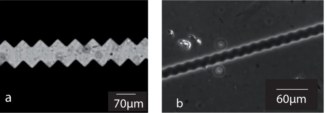
The second and third chapters are dedicated to the two fabrication techniques we implemented in our microfluidic channels. The principle of the techniques and the experimental protocols are detailed, followed by the characteristics of the isolated fibers and fiber suspensions we obtained. They are complementary techniques, the polymerization one allowing us to fabricate isolated fibers and fiber suspensions confined in the microchannel. Figure0.3-A shows a fabrication example of a single fiber and a suspension of fibers all perpendicular to the flow direction. The colloidal-assembly method is used to fabricate fiber suspensions at high concentrations flowing
as illustrated in picture B. The flow geometries also differ between the two methods: in the first one, channels are Hele-Shaw cells where a two-dimensional flow develops. In the second method, the flow is three-dimensional.
200μm A 40 μm40 μm B
single fiber:
fibers suspension:
Figure 0.3: Micrographs of fibers fabricated directly in the microchannels. A: we use a photo-polymerization technique to fabricate an isolated fiber (top picture) and a suspension of fibers all perpendicular to the flow direction. B: high-concentration fiber suspension fabricated with the colloidal self-assembly technique.
The fourth chapter presents an experiment to mechanically characterize the fibers fabricated with the photo-polymerization method. Even though this fabrication technique is used in many experimental investigations, there is no mechanical characterization method available yet. Here we fabricate a single fiber fixed across a microchannel subjected to the fluid drag force, similar to a "bending-beam" test. Using our experimental data of fiber deflection and results from a lubrication analysis, we obtain the fiber’s Youngs modulus. Figure0.4shows the successive deflections of the fiber.
fluid
60 μm
Figure 0.4: Snapshot of pictures showing the fiber bending as the fluid flowrate is increased, increasing the drag force on the fiber. This experiment was designed to provide us with a me-chanical characterization of the fiber fabricated with the polymerization technique.
We study in the fifth chapter the free transport of an isolated fiber confined in a Hele-Shaw geometry flowing far from the lateral walls. Experimental data complemented with 2D and
Contents 19
3D numerical simulations are used to investigate the fiber velocity with respect to the flow velocity, depending on its confinement and its angle with the flow direction. We also quantify the perturbation on the flow profile caused by the presence of a fiber. An example of this study is shown in figure0.5with a chronograph of a fiber flowing perpendicular to the flow direction.
100 μm δt=200ms
Figure 0.5: Chronograph of a fiber flowing freely in a confined microchannel away from the lateral boundaries. The fiber is fabricated perpendicular to the flow direction (first position on the left). We study the fiber velocity and trajectory depending on its initial orientation with the flow.
In the sixth chapter we modify the fiber and channel geometry of the previous study to make the channel width comparable to the fiber length. Interactions between the fiber and the lateral walls start to occur, leading to a beautiful oscillatory motion of the fiber as illustrated in figure
0.6. We describe the fiber oscillations as a sequence of three phases occuring in each oscillation period. We use the fiber’s angle to define a criterion to determine the occurence of each regime. We characterize the three phases in terms of fiber position, velocity along the flow direction and perpendicular to it, and in terms of angular velocity.
200 μm
Figure 0.6: Successive positions of a fiber oscillating between the two channel lateral walls. We observe such robust oscillations when the channel width is reduced to the fiber length, triggering interactions between the fiber and the walls. The motion is decomposed in a sequence of three regimes that we analyze in terms of position, velocity and angle.
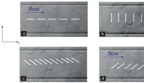
The seventh chapter presents our first results of flow of fiber suspensions in microfluidic ge-ometries going through a flow restriction. Taking advantage of the two fabrication techniques, we study fiber suspensions in two regimes. The first one concerns dilute suspensions of fibers fabricated with the photo-polymerization method where the initial state (position, orientation) of fibers is controlled. Figure0.7-A shows the example of a suspension where all fibers are fab-ricated parallel to the flow direction upstream of the restriction. In this regime, the fibers are
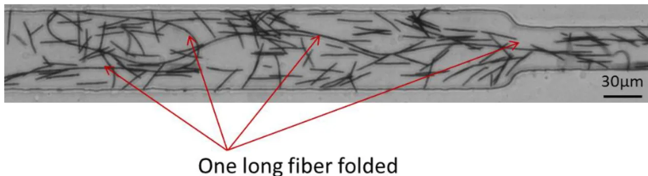
confined in a two-dimensional flow geometry. The second fabrication technique corresponds to more concentrated suspensions where the fibers are randomly positionned at the initial state and flow through a three-dimensional flow geometry. Figure0.7-B shows an example of 3D suspension flowing through a restriction. At such concentrations we observe the development of a heterogeneous distribution of fiber and the formation of flocs.
200μm
FLOW DIRECTION
A
B 40 μm
Figure 0.7: Two pictures showing the flow of a fiber suspension through a restriction in the channel. The top picture (A) shows the initial state of a suspension of fibers fabricated with the photo-polymerization technique all parallel to the flow direction, upstream of the restriction. The bottom picture (B) illustrates the case of a 3D flow where the fibers are fabricated using the super-paramagnetic-particle-assembly technique, leading to more concentrated suspensions. The fiber spatial distribution is heterogeneous, we observe the formation of flocs. Such collective dynamics will be studied in chapter seven.
The last chapter concludes this thesis. Experimental and numerical methods are detailed in the first four appendices. In the last appendix, I summarize other projects I participated in during my Ph.D. work.
C
H A P T E R1
S
TATE
-
OF
-
THE
-
ART REVIEW
In this first chapter we propose a review of some important studies in the literature on flow of fibers and fiber suspensions that are relevant for our study. Then, in a second part, we re-view recent technical achievements on fabrication techniques developed to produce particles in small flow geometries. We will focus on the photo-polymerization method [20] and the magnetic colloidal self-assembly method [22] that we implemented in our channels to fabricate in situ microfluidic fibers.
We start this review with studies on the flow of isolated fibers, first in an unbounded medium then in interaction with a boundary. The principle of the slender-body theory is explained through the example of a sedimenting fiber. Then we focus on the case of confined fibers: the flow of a fiber perpendicular to the flow direction and confined between two walls is described as well as the interactions between a fixed fiber and the boundaries in similar geometries. As the fiber concentration is increased, collective effects start to occur in flowing suspensions of fibers. We will present in particular effects of clogging, sedimentation and flocculation. Exhaustive reviews are available on fiber suspensions as well as particle microfabrication: see in particular Hubbe et al.[23], Guazzelli et al. [4] and Dendukuri et al. [24].
1.1
Flow of one fiber
The word "fiber" describes an elongated solid body. Its geometry is fully characterized by its section shape and aspect ratio: ratio of fiber length to diameter or thickness. Fibers can be found in many applications: paper, fiber-reinforced composite materials, wellbore-completion fluids in the oil industry. In such examples, fiber suspensions are carefully designed in terms of concentration, stiffness, roughness and interactions, among other parameters.
We focus in this first section on the viscous flow of isolated fibers. The cases of simple shear flows and Poiseuille flows are presented for unbounded media and flow near boundaries at small Reynolds numbers. We start with the principle of the slender-body theory which made
possible many theoretical and numerical work on flows of isolated fibers. We mention in par-ticular the case of a sedimenting fiber in an unbounded fluid.
1.1.1 Slender-body theory
Slender-body theory is an asymptotic technique to approximate the Stokes flow field around a body using its slenderness [13]. It allows to compute the force exerted by the fluid on the body. The principle of the method is to consider the slender body as a distribution of Stokeslets on its surface. The velocity on each little domain is given by the force per unit length exerted by the fluid on that point.
The slender-body theory can be applied for example to the case of a rigid cylindrical fiber trans-lating in an unbounded fluid of viscosityηat a constant velocity U. Calling a the fiber’s radius, l its length andε= (ln(l/a))−1, the force exerted on the fiber when its axis is parallel to the flow direction F∥and the force when it is perpendicular F⊥are given by [25]:
F∥≈ −2πηlεU (1.1)
F⊥≈ −4πηεlU (1.2)
The drag for the perpendicular motion is almost twice larger than the drag when the fiber is parallel. An important consequence of this result is found for the sedimentation of a fiber away from the flow boundaries. A fiber parallel to the vertical direction will sediment at a velocity twice larger than a perpendicular fiber. When the fiber is initially at an angle different from 0○ or 90○, this velocity difference between parallel and perpendicular motions will result in a drift of the fiber. Figure1.1illustrates the direction of the drift compared to the orientation of the fiber.
Vparallel Vperpendicular
DRIFT VELOCITY
mg
Figure 1.1: Drawing illustrating the drift of a fiber sedimenting with a non-zero angle with the vertical direction.
1.1.2 Fiber in a simple shear flow in an unbounded medium
Jeffery published in 1922 his work on the free transport of ellipsoids in simple shear flows [6]. He found two characteristic features. First, the particle’s centroid flows at the velocity of the fluid at that same location. He also showed that the ellipsoid experiences a periodic rotation
1.1. Flow of one fiber 23
depending only on the shear rate ˙γand the particle’s aspect ratio r. Figure1.2shows a view of such ellipsoid in polar coordinates.
θ
x
y
z
Φ
shear flow solid bodyFigure 1.2: Representation of an elongated body in a simple shear flow in polar coordinates.
Jeffery’s equation describing the angular velocity with the ellipsoid’s aspect ratio r is [6]: ˙ φ= − ˙ γ r2+1(r 2cos2φ +sin2φ) (1.3)
The integration of his equations leads to a family of curves described by the ellipsoid angleθ: tanθ= Cr (r2cos2φ+sin2φ) 1 2 (1.4)
Cr is a constant of integration called the orbit constant . In the absence of external forces or
interactions, the ellipsoid will flow indefinitely in a unique orbit. The maximal angular velocity ˙
φis obtained when the ellipsoid is perpendicular to the flow direction and minimal when it is parallel (θ=0). As a result, most of the flow is done when the ellipsoid is almost parallel to the flow direction. Every half period it flips rapidly (sometimes referred to as a "tumbling motion"). These results were generalized later on for the case of rigid bodies of revolution by Bretherton given a modification of r [7].
1.1.3 Fiber flow near a wall
The flow of a fiber near a solid boundary was investigated experimentally and numerically in simple shear flows and Poiseuille flows [9][10][26]. Questions addressed concerned the fiber’s velocity, orientation, and position relative to the boundary.
The case of a fiber transported in a Poiseuille flow near the boundary was investigated in a Hele-Shaw cell of aspect ratio 30 with a cell height much larger than the fiber length: ratio of 3 to 20 [10]. The fiber trajectory is observed in two planes of view and in particular within the channel height where the flow develops into a Poiseuille flow. Two fiber flow regimes are found, depending on the initial position of the fiber. At a distance to the wallδlarger than the fiber length l, fibers rotate periodically with a period of rotation in agreement with previous studies
in unbounded fluids. The presence of the wall does not have any influence on the motion. As the distanceδdecreases but stays above l/2, the rotation period is higher than the value predicted with the shear rate, regardless of the fiber orbit constant.
In the regime whereδ/l<1/2, interactions with the wall perturb the motion of the fiber. For fibers of high orbit constants, a "pole-vaulting" motion is observed (in French: saut à la perche) as illustrated in figure 1.3. The reference to the pole-vaulting discipline should not only be understood in terms of the successive angles of the fiber but also in terms of distance to the wall: the fiber systematically flows away from the wall to a distance comparable to half its length (l/2). As this position is reached, the fiber continues to periodically rotate but stays at the same distance. The principles of reversibility and symmetry of Stokes flow are not verified during a pole-vault motion, leading the authors to suggest that non-hydrodynamic forces such as mechanical contact are taking place. Low orbit constant fibers experience a similar motion but stay at constant distance to the wall.
Figure 1.3: Pole-vaulting trajectory of a fiber placed close to a boundary in a Poiseuille flow. Figure extracted from [10].
Similarly, in the case of a fiber near a wall in simple shear flow [9], a fiber initially perpendicu-lar to the boundary will rotate. In the regime far from the wall (δ>l) the angular velocity is in agreement with the Jeffery equations. At a closer distance to the boundary, the fiber will rotate at a higher velocity (in agreement with Jeffery using a correction on the shear rate) until it is aligned with the flow direction. No further rotation is observed within the field of view.
1.1.4 Sedimentation near a wall
A third example of a fiber interacting with a solid boundary is the case of sedimentation near a wall. Experiments supported with the slender-body theory report results on the position, orientation and velocity of a single rod inclined with the vertical direction sedimenting near a wall [27].
We recall that an inclined fiber in an unbounded fluid drifts during sedimentation. No rotation is observed, following the principle of reversibility of Stokes flows. As the fiber is approaching a wall, a rotation will occur in two different regimes depending on its initial angle with the vertical direction. Figure 1.4illustrates the trajectory observed in the two regimes: glancing and reversing.
1.2. Fibers in confined geometries 25
Figure 1.4: Drawing extracted from [27] showing two possible trajectories of a rod sedimenting near a vertical wall.
1.2
Fibers in confined geometries
We saw in the previous examples that the presence of a boundary perturbs the flow of an advected fiber. The case of a further interaction, when a fiber is confined between two flow boundaries, was recently investigated experimentally and numerically in the Ph.D. work of B. Semin (2010, [18]). In this study, a single fiber is placed parallel or perpendicular to the flow direction between two parallel walls. Figure1.5illustrates the flow geometry.
Figure 1.5: Experimental set-up for the study of a confined fiber between two parallel walls. The left drawing shows the configuration where the fiber is parallel to the flow direction. The right one is the perpendicular configuration. The parameters of particular interest are the fiber length L compared with the aperture width h0 and the channel width W. (Figure extracted from [17])
The experimental investigation of the parallel orientation is supported with 2D numerical sim-ulations considering an infinitely-long fiber. In the perpendicular case however, 3D calcsim-ulations are necessary to take into account the flow circulation around the fiber tips.
The drag force is proportional to the fluid velocity and viscosity as expected in Stokes flows. Drag coefficients for both orientations are found to linearly increase with the confinement how-ever their behaviour differ towards the limit of high confinements (fiber diameter≈h0). In the parallel case, the drag coefficient increases with the confinement but does not diverge. The drag coefficient of the perpendicular configuration increases faster with confinement and even-tually diverges due to the restricted flow path. Figure1.6 shows the evolution of both drag coefficients.
Figure 1.6: Experimental (symbols) and numerical results (lines) of drag coefficients for the parallel (left) and perpendicular (right) orientations of the fiber reported with the degree of confinementβ.βis defined as d/h0where d is the fiber diameter. In both cases, drag coefficients increases linearly with the confinement, diverging in the limit of high confinementsβ=1 only in the perpendicular case. Figure extracted from [17].
At Reynolds number higher than 20, the central position of the fiber between the two walls becomes unstable. The fiber starts to oscillate between them. These experimental observations are supported with modeling work.
The free transport of a unique fiber in a similar geometry was numerically investigated by Champmartin et al. [19] and supported with asymptotic developments. The flow geometry is an infinitely-long cylindrical particle positioned perpendicularly to the flow direction and freely transported between two boundaries. The calculation is therefore two-dimensional. The position of the particle relative to the boundaries as well as the effect of confinement on its velocity is explored. The authors found in particular that in the limit of small confinements, the particle flows at the maximal velocity of the fluid in the Poiseuille profile. Towards high confinements, the particle flows at the mean flow velocity. Figure1.7illustrates these results of the particle’s velocity.
1.3. Collective dynamics of fibers in suspensions 27
Figure 1.7: Results of particle velocity (divided with the mean flow velocity U) reported with the transverse position e and the particle confinement k. e=0 corresponds to the center of the channel, emaxto the position of the boundaries. Figures extracted from [19]
Contrary to fibers, the free transport of spherical particles in confined geometries has recently been investigated experimentally [28]. The development of microfabrication techniques allows to design flow geometries with obstacles, confinement, in a controlled way.
1.3
Collective dynamics of fibers in suspensions
We present in this section some examples of fiber collective dynamics observed in flowing sus-pensions of fibers.
Clustering
Spontaneous aggregation of fibers in supensions occur in several different physical situations. The first example is a suspension of sedimenting fibers. As recalled earlier in the chapter, a unique fiber inclined with the vertical direction sediments with a drift. Then, as it approaches a solid boundary, its motion is perturbed and the fiber rotates. When many of such fibers are dispersed in a fluid with random orientations, collisions will occur between drifting fibers at a probability increasing with their concentration.
Recent theoretical studies predict that the sedimentation of dilute monodisperse fiber suspen-sions is an unstable flow, leading to the formation of fiber clusters [29]. Heterogeneities in the distribution of fibers and in their velocity increase as the clusters sediment faster than isolated fibers. Recent experimental and numerical work agreed with these theoretical predictions and showed results dependent on the fiber concentration in suspension. The case of dilute suspen-sions was for example investigated by Butler & Shaqfeh [30] at low Reynolds numbers (10−2). They observe the continuous formation and deformation of fiber clusters, agreeing with the experimental observation [31]. Such clusters obtained experimentally [31] are shown in fig-ure1.8. Fiber clusters flow faster than isolated fibers and occasionally flip due to back flow of regions of fluid with less fibers. Strong orientation in the direction of gravity is also observed. In the semi-dilute regime, at higher concentrations, fibers entangle to form a semi-rigid net-work hindering the sedimentation motion. The orientation of fibers however was found not to depend on the concentration regime [4].
Figure 1.8: Experimental pictures of the sedimentation of a fiber suspension at two different time steps, extracted from [31]. The suspension is homogeneous initially. Time is made dimensionless by the time taken by an isolated fiber to fall half its length. In photograph A, time t=5, in photograph B t=60. The second picture shows the apparition of fiber aggregates, leading to fast-sedimenting clusters in the suspension.
Clustering of fibers is also observed in sheared suspensions and called in this situation floccu-lation.
Flocculation-related issues in papermaking has actually been a driving element for research on fiber suspensions for many decades [32]. Flocculation describes the aggregation of fibers into clumps when a highly-concentrated suspension of fibers is sheared. Figure1.9 presents an example of flocs obtained from industrial fibers suspended in a water-based fluid. Paper manufacturers try to avoid flocculation as flocs in the cellulose fiber suspensions are responsi-ble for heterogeneities on the final paper sheets. Heterogeneities imply that there will be weak regions in the paper, leading to mechanical fragility. They are also responsible for unaesthetic features.
Figure 1.9: Pictures of fibers flocculated in suspensions. Initially dry fibers (left) are dispersed in a water-based fluid (middle). Entangled fibers form a network structure (right). Pictures extracted from CemNET Schlumberger documentation[33].
1.3. Collective dynamics of fibers in suspensions 29
When many of fibers are suspended in a sheared fluid, their rotating motions will cause col-lisions unless their concentration is too small [6]. Fibers collisions are the first cause of the formation of flocs, leading Mason [2][3] to propose a concentration threshold for a given sus-pension. He introduced the "critical fiber concentration" based on the idea that a rotating fiber describes a spherical volume whose diameter is given by the fiber length. Then, in order to compute a probability of collisions and of inter-fiber contacts, Kerekes introduced a crowding factor [34] [35]. This parameter characterizes a suspension by the number of fibers in the spherical volume corresponding to the rotation volume of one fiber.
In this mechanical point of view, flocs can form and deform continuously. A mechanism ex-plaining their persistence in flow was proposed based on the idea that fibers temporarily bend under shear [23]. Fibers collide and entangle with their neighbouring particles, blocked in bent configurations. Friction between fibers and elastic energy stored in the bending give flocs their strength and persistence through flow.
The main factors enhancing flocculation are typically high flow velocities, low viscosities, high fiber aspect ratio and stiffness [23][35][36]. Such results obtained with experimental stud-ies are largely complemented with literature on numerical work where the technical difficul-ties associated with fibers experiments are overcome. For example, simulations are used to tune inter-fiber friction without modifying other fibers parameters or taking into account other forces [37]. Similarly, many numerical studies can be found on sedimentation of fibers [30] and flows of fiber suspensions interacting with boundaries [38].
The mechanism proposed for the formation of flocs, often referred to as "bend, straighten and lock" [23] suggests that flocs can break when subjected to forces higher than the friction and stored elastic forces holding them together. Shear flows will tend to make them rotate [39]. However, extensional flows have been shown to efficiently break them [40] [41] [42]. This behavior is of particular interest in this collaboration work between Schlumberger and the ESPCI-PMMH. In applications of lost-circulation curing introduced in the previous chapter, fibers are mixed with drilling fluids to block flow through natural or induced fractures, fissures or highly porous zones [1]. The presence of flocs in the suspensions downhole is believed to be one of the mechanisms of sealing. Depending on fracture sizes, pressure, flocs may however be broken at the entrance of the fracture where maximal extensional stresses occur. Typically wellbore diameter is of the order of 20 cm, to be compared with typical fracture sizes of a few millimeters.
Jamming
Another mechanism proposed for the clogging of flow restrictions in lost-circulation curing is jamming of fiber suspensions. Particle suspensions jam when their volume fraction is high enough. Recent rheological studies showed that this jamming threshold is however reduced when the suspension experiences shear [43], with an increased effect observed for suspensions of anisotropic particles. In extensional flows of jammed suspensions such as flows through re-strictions, particles concentration is reduced downstream of the restriction [5].
1.4
In situ particle microfabrication techniques
We now present recent technical achievements in the production of particles in microchannels. The two techniques reviewed here were implemented in our micromodel investigation.
1.4.1 Lithography method of particle fabrication
1.4.1.1 Fabrication principle
A technique to fabricate microparticles directly into microfluidic channels has been recently developped in Patrick Doyle’s research group at MIT [44]. The fabrication uses the principle of microscope-based projection photolithography. Initially invented and developped for the mi-croelectronics industry [45], this technique would enable the fabrication of micrometric and submicrometric features in photo-sensitive resins by means of projecting a mask onto a silicon wafer with an optical microscope objective. It was then succesfully applied to soft-lithography techniques as an alternative to the now-traditionnal clean room fabrication method and its expensive costs [46]. A few years later, Dendukuri et al. applied the same principle to mass-fabricate micrometric-shaped particles directly inside microfluidic channels where they can then flow [20].
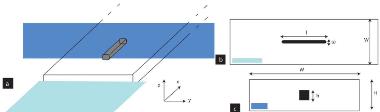
Similarly to its microelectronics precursor, the fabrication set-up only requires a microscope, a lithography mask, a UV-light source and an all-PDMS (polydimethylsiloxane, Sigma, see AppendixA) microfluidic channel. The channel is placed on an inverted microscope and filled with a solution of oligomer and photo-initiator. A photolithography mask of the particle shape is placed in the field-stop position of the microscope. We expose the channel to a pulse of UV-light through the lithography mask; the particle shape gets projected into the microchannel and focused in its center where the exposed portion of fluid crosslinks within tens of microseconds. A schematic drawing of the process is described in figure1.10.
The polymerization process is a free-radical reaction taking place in four steps: photolysis, chain initiation, propagation and termination. During the photolysis, the photo-initiator re-acts with UV-light to produce two free radical species as illustrated in figure1.12with the com-mercial photo-initiator Darocur 1173 (2-Hydroxy-2-Methylpropiophenone, Sigma, 1.11). The radicals react with an acrylate group of the oligomer to form a reactive alkyl monomer radical, initiating the reaction. Crosslinking occurs during the propagation step where the radicals re-act in chain with other oligomer molecules. The termination step happens as radicals interre-act or recombine to give neutral species. These four steps are described for the case of acrylate-monomers in figure1.13.
1.4.1.2 Particle characteristics
The particles fabricated using projection photolithography have a rectangular or square cross-section due to the geometry of the channel. Particle length and width are proportionnal to the dimensions on the lithography mask modulo a factor given both by the magnification of the objective and a constant from the microscope itself.
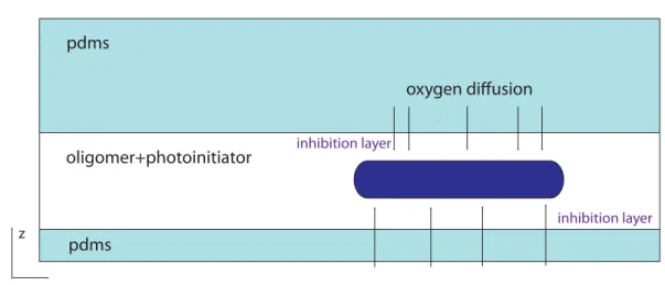
The particle height is given by the channel height, since the projection of UV-light is done through the fluid along this direction. The method takes advantage of the permeability of PDMS to dioxygen so that the fabricated particle doesn’t stick to the channel walls and flows
1.4. In situ particle microfabrication techniques 31 glass pdms channel objective particle-shaped mask UV-light x z y pdms pdms oligomer+photoinitiator oxygen diffusion inhibition layer inhibition layer x z a b
Figure 1.10: Schematic drawing of the fabrication method (a): a particle-shaped mask (here, square shape) is projected into an oligomer solution containing some photo-initiator, by means of a UV light source and through a microscope objective. The right drawing (b) shows the inhibition layers where the presence of dioxygen terminates the polymerization. The particles can then flow in the fluid downstream of the microchannel.
O
O
O
O
nO
OH Photo-initiator Polyethyleneglycoldiacrylate Darocur 1173Figure 1.11: Photo-initator Darocur 1173 (Sigma)
downstream. Dioxygen inhibits the polymerization reaction as it reacts with radicals to form an oxygen-oxygen link (see in eq. 1.5 the chemical reaction: R designing the radical, M the monomer).
R M.n+O2− >R MnOO (1.5)
A thin layer of fluid along all the channel walls contains dioxygen that has diffused through the PDMS. Consequently, the portion of fluid polymerizing along the channel height is reduced by these so-called inhibition layers (right drawing of1.10). The layer thickness is independent of the channel height [47]. It was characterized by a one-dimensional model of light penetration and reaction kinetics to study the influence of the concentration of photo-initiator, the light in-tensity and channel height. In conclusion, the three dimensions of the particle are determined by the optical properties of the system (microscope+objective+mask dimensions) as well as by
OH
UV .
OH
.
benzoyl radical alkyl radical
Figure 1.12: initiation
Initiator +UV Radical R
R + CH2=CHCOOR RCH2C HCOOR
RCH2C HCOOR + [CH2CH]n+1 RCH2CH [CH2CH]n CH2CH
COOR COOR COOR
=RM[M]nM
RMM + RMM RMM MMR RMM +R RMM R
COOR
Figure 1.13: radical photopolymerization reaction
the channel height and chemistry.
The mechanical properties of the particles are governed by the nature of the polymer used for the fabrication. It can play a major role in the targeted flow application. For example Attia et al [48] developed a flow sensor using the in situ polymerization of a spring-like structure fixed inside the channel. In this case, the elongational properties of the sensor depend on the nature of the polymerised network.
1.4.2 Self-assembling colloids to fabricate filaments
1.4.2.1 Fabrication principle
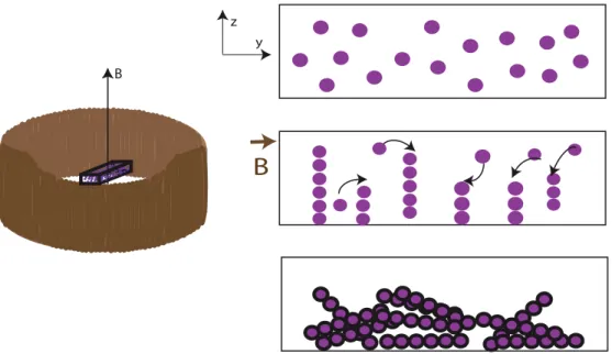
We introduce a second fabrication method which was originally developed experimentally dur-ing the PhD work of C. Goubault at ESPCI (2004, [22]) to fabricate elastic filaments in mi-crochannels. These filaments are made of self-assembled super-paramagnetic colloids which are bridged together by polymer chains. Initially developed to provide micromechanical sen-sors [21], they have been used as a basis for active micro-swimmers [49]. Babataheri et al. demonstrated that they could be anchored on a surface to form carpets of cilia, driven by a
1.4. In situ particle microfabrication techniques 33
variable magnetic field [50]. They studied the collective beating dynamics for such structures while Coq et al. [51] reported on beating regimes of isolated filaments actuated by a magnetic field.
Super-paramagnetic particles are freely suspended in solution and subject to Brownian motion. When a magnetic field is applied, each colloidal particle acquires a magnetic moment m paral-lel to the magnetic field B and of intensityνχB whereνis the particle volume,χits magnetic susceptibility and B the magnetic field intensity. Dipolar interactions induce self-assembly in one-dimensional structures aligned with B.
The magnetic interaction energy between two dipoles depends as 1−3cos2θ with the angleθ formed by the two moments and the direction of the magnetic field. Figure1.14gives its full expression withµ0 the vacuum permeability. The minimal energy is obtained when the two
dipoles are aligned, however if the angle is maintained below:θ<arccos(1/ √
3)the interaction stays attractive. The dipoles are in the "attractive region" as illustrated in figure1.14and can come in close contact. The formation of chains with more than one array of colloids is therefore possible. attraction region repulsion region m m r θ
Magnetic interaction energy
E= 1-3cos θ
r
2 34 Π
μ
0m
2B
Figure 1.14: Dipole dipole magnetic interactions
Since the particles are super-paramagnetic, the filaments are not permanently formed. Once the magnetic field is removed the colloids move freely and independently in the solution due to brownian motion. One way to bridge the colloids and form permanent filaments is to use polymer chains bridging colloids together when they are aligned in chains in very close contact [52]. This mechanism has a threshold: it can only work when the distance separating the two colloids is very small, meaning that the intensity of the magnetic field should be high enough to bring colloids to close contact. Other methods are possible, for instance using biological linkers like antibodies and antigenes [22].
The set-up requires a microscope equipped with a coil to produce a vertical magnetic field, a microchannel and super-paramagnetic particles. The fabrication takes place in three steps as described in figure1.15. The solution of superparamagnetic colloidal particles and polymer in water is introduced in a microchannel or capillary tube. The flow is stopped and a vertical magnetic field is applied. During this step, the attractive magnetic interactions cause the colloids to self-assemble as chains along the vertical direction. When two colloids get close to each other, polyelectrolyte binding cause the polymer chains adsorbed on their surface to
bridge them permanently together, acting like linkers [53]. In the last step, the magnetic field is removed causing the colloidal particles to loose their magnetic moment though they are still held together by the polymer. The filaments are permanently formed and sediment in the channel with random directions.
y
z
B
B
Figure 1.15: Principle of fabrication of fibers using super-paramagnetic particles
1.4.2.2 Filaments characteristics
The filaments are characterized by a cylindrical shape: their diameter is given by the diameter of the colloidal particles. Their aspect ratio can be very large: the fiber length is only governed by the channel height and the volume fraction of particles available. Babataheri et al. typ-ically obtained 200µm-long filaments. Since the colloidal particles contain nanoscopic grains of iron oxyde (Fe2O3), they are denser than the aqueous solution. During the application of the vertical magnetic field, their density will tend to make them sediment to the bottom of the channel, competing with the magnetic attractive forces between two particles along the verti-cal direction. This property can be used to get filaments much shorter than the channel height by adding a sedimentation step before the application of the magnetic field [51].
The concentration of filaments in solution depends on the initial volume fraction of colloids for a given channel geometry. When applying the magnetic field, the columns formed by the assembled colloids show a strong ordering: the dipolar magnetic interactions between columns are responsible for a constant separation distance between them. Liu et al. [54] characterized this ordering and showed that the separation distance follows a relation with the chain length: d=1.33L0.37. It also means that there is a maximum concentration of filaments which depends on the channel height. At constant volume fraction, the higher a channel the longer the chains forms, which in return decreases the distance between filaments.
Filament elasticity depends on the nature of the polymer bridging the particles together. A bending modulus of 10−23J.m was measured [22] for filaments obtained with the same particles
1.4. In situ particle microfabrication techniques 35
and polymer chains as in our experiments. As they are formed as chains of spherical particles, their surface roughness is given by the particles radius and cannot be easily modified.
C
H A P T E R2
L
ITHOGRAPHY FABRICATION OF FIBERS
The motivation of this work is to study the flow dynamics of isolated fiber and suspensions of fibers in confined flow geometries. Our objective is to use microfluidics to set up an experimen-tal model system where we can observe the flow and vary parameters associated with the flow geometry and with the fibers. Experiments of fiber flow at the microfluidic scale requires the introduction of fibers inside the channel. However microsized fibers of controlled geometry are not commercially available. Another technical difficulty comes from the flow restrictions inside all the microfluidic connections where the fibers could accumulate and create flow blockage. A solution is to use modern techniques of micro fabrication to produce fibers in situ. We present in this chapter how we adapted the microparticle fabrication method based on photolithogra-phy which was introduced in the first chapter of this manuscript (1.4.1.1) for the fabrication of microscale fibers. This technique enables the fabrication of fiber-shaped particles with an excellent control of their geometry, directly inside the microchannel preventing risks of flow plugs. This way we can tune the mechanical properties of the fibers as well as their surface state. We will describe the fabrication of both isolated fibers and fiber suspensions with an ex-cellent control over their initial state: orientation of the fiber, placement inside the microfluidic geometry.
2.1
Fabrication principle
The method uses the principle of microscope-based projection lithography which was intro-duced in the first chapter of this thesis (1.4.1.1). The idea is to project UV-light through a fiber-shaped mask into the channel where one wants to make the fiber. The channel is filled with a solution of oligomer and photo-initiator chosen for the properties of its polymerized phase. The solution crosslinks under UV-light: the illumination of the target fluid region makes it poly-merize within tens of milliseconds. A schematic drawing of the method is presented in Figure
2.1.
Since we are projecting a two-dimensional fiber shape through the height of the channel, we create fibers of typically rectangular cross-sections. The fabricated particles are able to flow inside the channel because thin layers of fluid along the channel top and bottom walls remain unpolymerized. This inhibition property of such layers is taken advantage of for the design of the fiber geometry as we will see later in this chapter.
Figure 2.1: In situ fabrication of fibers using a projection method. The left drawing shows all the elements necessary for the projection on the microscope. They are indicated on the picture of the experimental set-up (right): A: channel filled with oligomer and photo-initiator solution, placed on the microscope. B: UV-light source C: shutter D: filter E: fiber-shaped mask and F: syringe pump. The bottom picture shows the mask holder with an actual mask in place in the left slot. A white fiber shape is drawn in its center.
2.2. Experimental protocol 39
2.2
Experimental protocol
2.2.1 Experimental set-up
We build a fabrication and flow platform in a single set-up as illustrated in2.1. A transparent microchannel is made with traditionnal soft-lithography techniques in polydimethylsiloxane (PDMS, Sylgard 184, Corning). Details of the microfabrication can be found in AppendixA. It is then placed on the stage of an inverted microscope (Zeiss Axio Observer) equipped with a UV-light source, a shutter and a fiber-shaped mask (Shutter Uniblitz V25, Lamp HBO 130W). The UV light is filtered through a narrow-UV-excitation filter set (11004v2 Chroma) with an emission peak atλ≻390 nm.
Anti-UV coated tubings are used to connect the inlet and outlet of the microchannel to a syringe or fluid reservoir. We use two methods to start and stop the flow: the first one consists in varying the vertical distance between the inlet and outlet fluid levels to induce a pressure-imposed flow. The second method consists in imposing a constant flowrate with a syringe pump delivering fluid into the inlet tubing. Our geometries require a small flowrate of the order of nL.s−1. We use a NeMESYS (Cetoni) syringe pump capable of delivering such small flow in a stable continuous manner.
2.2.2 Microfluidic channel
We work with rectangular-section channels where the width is typically ten times larger than the height. Orders of magnitude of channel dimensions are: width 100µm, height 10µm, length several centimeters. Such confinement is required by the fabrication technique because of the constraint imposed by the channel height on the fiber dimension. As we explained in the introduction chapter 1.4.1.1, fiber width and length are independent of the channel geometry however its height is given by the channel height. We will develop this aspect in more details in the section dedicated to fiber geometrical design2.3.1.
2.2.3 Oligomer solutions
The choice of the oligomer solution and the concentration of photo-initiator should be made in regards with the targeted mechanical properties of the fabricated fiber. The nature of the photo-initiator is also important from a technical point of view: its excitation wavelength should be matched with the light source available and the set-up constraints. We worked with a solution of polyethyleneglycoldiacrylate (PEGDA, Mw=575, Sigma) with Darocur 1173 photo-initiator (PI) (2-hydroxy-2-methylpropiophenone, Sigma) at 10 wt%.
The density of the oligomer/PI solution is 1.12 g.cm−3and its kinematic viscosity 52.2 mm2.s−1 (experimentally measured using capillary rheometers and densitometer).
2.2.4 Lithography mask design
A fiber shape is projected into the channel using a lithography mask specifically designed for a given fiber geometry. We place this mask in the field stop position of the microscope to get it focused into the objective image plane (see picture of the set-up in2.1-E). The mask is designed with AUTOCAD 2009 and printed at a resolution of 50800 dpi at SELBA S.A (Switzerland). It
consists of a transparent-fiber shape drawn in the center part of a 25mm-diameter black disk to be conveniently placed in the microscope holder. The highest printing resolution available was used to limit defects on the border line and black spots inside the fiber shape. Examples of fiber masks are presented in figure2.2. Figure2.3shows pictures of two masks, one printed with a poor resolution and one with the highest one.
Figure 2.2: Possible designs of fiber-shaped lithography masks. The first one is used for a single fiber, the three others are used for fabrication of groups of fibers with a given orientation.
2.2.5 Light shutter
We equipped the Zeiss microscope with an electronic shutter (V25, Uniblitz) capable of a min-imum window time of 10 ms (from pulse sent to opening and closing of the shutter). The shutter is mounted between the microscope and the UV-light source (HBO lamp) as illustrated in picture 2.1. Its blades are treated to resist to high temperature from UV-exposure. We control the opening time (=duration of the light pulse for the fabrication) and the opening fre-quency (for the fabrication of several fibers in the channel) using a computer-based Labview programme. We wrote the programme to dialogue directly from the PC to the shutter driver (VCM-D1 Single Channel, Uniblitz). This will be particularly useful in the future as a single Labview programme can be used to control several pieces of equipment of the set-up simulta-neously: shutter, camera, electronic microscope stage.
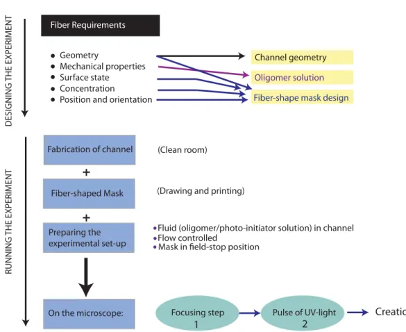
2.2.6 Protocol
2.2.6.1 Workflow
We describe here the typical work flow of a fabrication experiment. The preparation prior to the experiment should involve the design of the mask for the desired fiber geometry, the design and fabrication of the microchannel accordingly, and placement of the channel and mask on the microscope. A camera is used for direct observation of the channel. The first step is the optical focusing of the fiber-shape mask. It consists in making sure that the microscope is set with the mask placed in the image plane of the lens. This step is described in the next section. The second step is to get a stable continuous flow or stop the flow, according to the need. As mentioned above, either a syringe pump or pressure-imposed flow will be used. Then
2.2. Experimental protocol 41
100μm
300 μm
Figure 2.3: Examples of two printing resolutions of lithography masks. The top micrograph shows a fiber-shaped mask printed at 50800 dpi. The bottom micrograph shows a channel designed with a restriction, printed at 10000 dpi.
the user positions the channel using the stage so that the fiber shape will be projected at the right location inside the channel. Finally, the user programs the shutter via the computer to illuminate the channel for a given duration. All these steps are described in a workflow diagramme presented in figure2.4.
2.2.6.2 Optical focusing
The fabrication requires the user to carefully focus the projected mask structure into the chan-nel. Microscope objectives are typically corrected in visible light for achromatic aberrations. These aberrations are caused by the dispersion of the lense refractive properties with wave-length. A calibration of the optical system is necessary prior to fabrication since it requires UV-light: an object focused with visible light will not be focused anymore with UV-light in the channel. This is particularly true of high-magnification objectives which have a short depth of field.
For an objective 10X, a preliminary focusing of the fiber-shaped mask is realized with visible light and no shift is applied. For objectives 20X and higher, the distance of "defocusing" is de-termined in a test channel and applied before each fabrication, following the focus settings. On our microscope, for the X40 objective the defocusing was a quarter of full knob rotation.
Fabrication of channel
Fiber-shaped Mask
(Clean room)
(Drawing and printing)
Preparing the experimental set-up
Fluid (oligomer/photo-initiator solution) in channel Flow controlled
Mask in field-stop position
Focusing step Pulse of UV-light Creation of fiber
On the microscope: 1 2 DESIGNING THE EXPERIMENT RUNNING THE EXPERIMENT Fiber Requirements Geometry Mechanical properties Surface state Concentration
Position and orientation Fiber-shape mask design
Oligomer solution
Channel geometry
+
+
+
Figure 2.4: A to Z steps for designing and running a fiber fabrication experiment with the lithography technique
The resolution of our optical system can be similarly characterized based on the type of ob-jectives used for the fabrication. We call resolution the smallest distance between two object structures at which these objects are imaged separately. A theoretical resolution limit was first introduced by Abbe (1880) and can be computed using the numerical aperture of the objectives. Table2.1gives the theoretical resolutions for all the objectives used in our experimental tests. Note that microscope objectives have vary different optical transmission in UV-light wave-lengths. A "good" objective for other microscopy applications may not be useful at all for the photopolymerization method.
2.3
Fiber characteristics
2.3.1 Geometrical design: from the mask to the fiber
As the fabrication technique relies on the 2D projection of a fiber-shape through the channel height, we cannot fabricate cylindrical fibers but rectangular cross-section fibers and in our particular approach, square cross-section fibers.