HAL Id: hal-00573159
https://hal.archives-ouvertes.fr/hal-00573159
Submitted on 21 Jan 2020
HAL is a multi-disciplinary open access
archive for the deposit and dissemination of
sci-entific research documents, whether they are
pub-lished or not. The documents may come from
teaching and research institutions in France or
abroad, or from public or private research centers.
L’archive ouverte pluridisciplinaire HAL, est
destinée au dépôt et à la diffusion de documents
scientifiques de niveau recherche, publiés ou non,
émanant des établissements d’enseignement et de
recherche français ou étrangers, des laboratoires
publics ou privés.
S. Hage-Ali, N. Tiercelin, P. Coquet, R. Sauleau, V. Preobrazhensky, P.
Pernod
To cite this version:
S. Hage-Ali, N. Tiercelin, P. Coquet, R. Sauleau, V. Preobrazhensky, et al.. A millimeter-wave
inflat-able frequency-agile elastomeric antenna. IEEE Antennas and Wireless Propagation Letters, Institute
of Electrical and Electronics Engineers, 2010, 9, pp.1131-1134. �10.1109/LAWP.2010.2096405�.
�hal-00573159�
.
Abstract—This letter reports a millimeter-wave frequency agile microstrip antenna printed on an ultrasoft elastomeric PDMS substrate. The microstrip patch antenna is supported by a PDMS membrane suspended over an air cavity. The distance H between the patch and the ground plane, and thus the resonant frequency of the antenna, are tuned using pneumatic actuation, taking advantage of the extreme softness of the PDMS membrane. A continuous frequency shift varying from 55.35 to 51 GHz (≈≈≈≈8%) has been obtained for a tuning range of H between 200µm and 575µm. In all configurations, the antenna remains matched and its radiation characteristics are very satisfactory.
Index Terms— Inflatable, Membrane, PDMS, Reconfigurable antennas, Tunable.
I. INTRODUCTION
econfigurable antennas are increasingly needed for high-speed wireless communications and high-resolution sensing systems at millimeter waves [1]. Recently there has been a growing interest for frequency agile antennas due to the multiplication of wireless standards in close proximity to each other. Microstrip patch antennas are widely used because they are low-cost, light-weight, low-profile and compatible with MMIC technology. Various approaches have been implemented to tune their resonant frequency. Electrical solutions based on varactors [2, 3] and PIN diodes [4] have been reported. Many mechanical reconfiguration systems have been also proposed in the literature. In the early eighties, Lee
et al. [5] introduced a manually-reconfigurable circular
microstrip antenna with an air gap. Reconfigurable antennas using plastic deformation magnetic actuation [6] and tunable MEMS capacitors [7] were also reported. In [8], an electrostatically-actuated micromachined copper ground plane has been used to tune a microstrip antenna from 16.8 to 17.82 GHz (6%), and in [9] electrostatic actuation has been implemented to move a microstrip patch antenna fabricated on a flexible Kapton substrate, leading to a tunability of 2.1% (between 16.91 and 16.64 GHz). A similar topology on PET
Manuscript received September. 11, 2010. This work was supported partly by the French Délégation Générale pour l’Armement (DGA).
S. Hage-Ali, N. Tiercelin, P. Coquet, V. Preobrazhensky, and P. Pernod are with Joint International Laboratory LEMAC, IEMN UMR CNRS 8520, ECLille and Université des Sciences et Technologies de Lille, PRES Lille Nord de France, 59651 Villeneuve d’Ascq, France. (e-mail: [email protected] ; [email protected]).
R. Sauleau is with the Institut d’Electronique et de Télécommunications de Rennes (IETR), UMR CNRS 6164, Université de Rennes 1, 35042 Rennes cedex, France.
substrate has been recently discussed in [10] with a tunability of 3.6% at 10 GHz.
One of the key issues for elaborating mechanically reconfigurable antennas at millimeter waves consists in finding materials with suitable electromagnetic and mechanical properties. In this work, we use polydimethylsiloxane (PDMS) as an antenna substrate. PDMS is an extremely flexible polymer with very low Young’s modulus (EYoung=2 MPa) and
is compatible with a number of silicon micromachining techniques. The feasibility and performance of PDMS-based millimeter-wave transmission lines and microstrip antenna arrays have been demonstrated in [11-13]. Recently PDMS has been used in the development of stretchable dipole antennas filled with liquid metal at 1.5 – 2 GHz [14, 15].
In this letter we describe a PDMS-based frequency-tunable microstrip antenna in the 50-60 GHz band. Pneumatic actuation is used to reconfigure a PDMS membrane supporting a patch antenna over an air-filled cavity of variable height, resulting in a frequency shift. First we briefly explain the principle of operation of a mechanically tunable antenna over an air cavity (Section II). The antenna design and fabrication process are then described in Section III. The impedance and radiation characteristics of the tunable antenna are presented in Section IV. Results and limitations are discussed in Section V. Conclusions and perspectives are given in Section VI.
II. BACKGROUND
The resonant frequency Fres of a rectangular patch antenna
can be approximated at first order using the transmission line model described in [16] e e res
L
c
F
ε
2
=
, with Le= L+2∆L (1)where c is the speed of light in vacuum, Le the effective length
of the antenna, εe the effective dielectric constant, L the
physical length of the patch, and ∆L the length of the fringing fields. When considering a microstrip antenna over an air cavity of tunable height (Fig. 1), the resonant frequency is influenced by two opposite effects: increasing the cavity height results in lowering the effective dielectric constant εe (which
induces an increase of the resonant frequency) and simultaneously in larger fringing fields ∆L (which tends to decrease the resonant frequency). For small values of H, the first effect is predominant, whereas for larger values of the cavity height, the influence of ∆L is more pronounced. These trends are depicted in Fig. 2.
Sami Hage-Ali, Student Member, IEEE, Nicolas Tiercelin, Philippe Coquet, Ronan Sauleau, Senior
Member, IEEE, Vladimir Preobrazhensky, and Philippe Pernod
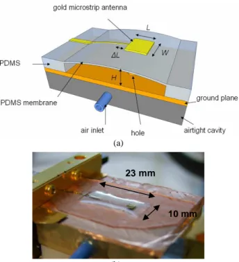
Fig. 1. Geometry of a microstrip antenna suspended over an air cavity.
Fig. 2. General trend of the variation of resonant frequency of an antenna suspended over an air cavity of variable height.
III. DESIGN AND FABRICATION
The geometry of the membrane-supported antenna studied here is represented in Fig. 3a. A rectangular patch is supported by a 20-µm-thick PDMS membrane over an air-filled cavity. The patch is fed by a microstrip line, first printed on bulk PDMS, then onto the membrane. The dielectric properties of PDMS at millimeter waves are given in [11]: εr=2.68 and tanδ=0.04. A specific metal transfer process has been developed to fabricate membrane-supported PDMS antennas. The technological process, fully described in [13], enables one to overcome the difficulty of PDMS micrometer-thick metallization due to its high thermal expansion coefficient and low adhesion to metal. Thanks to the PDMS mechanical properties, the membrane is easily and strongly deformed by pneumatic actuation through holes in the ground plane. This allows controlling the height of the patch, and thus the resonant frequency of the antenna. The inflated prototype is shown Fig.3b. The designed structure and actuation scheme enable to overcome limitations for similar designs due to electrostatic actuation that has a limited displacement, and less deformable materials that require larger actuation forces [8-10].
IV. NUMERICAL AND EXPERIMENTAL RESULTS
A. Results in impedance
1) Experimental setup
The experimental setup in V-band is depicted in Fig. 4. The impedance measurements have been performed using an Anritsu Universal test fixture 3680V coupled to an Agilent E8361A network analyzer with TRL calibration. The antenna cavity is filled precisely with air using an electronic NE100 syringe pump. Experimentally, the value of H is varied between 90µm (deflated position) and 575µm (inflated position) with an inserted air volume of 55µl. This volume is
(a)
(b)
Fig. 3. (a) Schematic view of the antenna (nominal flat design: H=200µm,
W=3350µm, L=2250µm). (b) Inflated microstrip antenna prototype with H=
2mm for demonstration purpose
Fig. 4. Experimental setup.
compatible with integrated fluidic micropumps. The flat position corresponds to H=200µm. The lower value of H=90 µm is determined by possible adhesion of the membrane on the ground plane. H has been measured using a Hirox microscope by focusing on the patch, then, using a high precision z-translation stage, focussing on the ground plane, and measuring the vertical displacement with a micron-scale precision. This setup allows measuring the impedance and cavity height simultaneously.
2) Resonant frequency
The variation of the antenna resonant frequency has been studied numerically using Ansoft HFSS (version 11.1) and experimentally with the proposed setup. The idealized HFSS configuration is shown in Fig. 5, and the numerical and experimental data are represented in Fig. 6. Measurements show that the resonant frequency increases from 53.9 GHz to 55.4 GHz for 90µm < H < 160 µm (this is due to the decrease
23 mm
Fig. 5. Numerical model for the antenna prototype.
Fig. 6. Resonant frequency of the antenna as a function of H. HFSS simulations Experimental data.
The main result is that the antenna is tuned from 55.35 GHz to 51 GHz for H varying between 200 µm (nominal) and 575 µm. This corresponds to a relative agility of 8.2% for a 287% variation of H. A satisfactory agreement between numerical modelling and experimental results is obtained. The difference is attributed to the imperfect linearized simulated geometry described in Fig.5.
3) Reflection coefficient and bandwidth
The antenna reflection coefficients S11 measured in the
50-60 GHz band for four positions of the membrane are given in Fig. 7, and the comparison between experiment and numerical results for the flat case is represented in Fig. 8. On each experimental S11 curve, one can observe two peaks. The first
one (~ 55.5 GHz for the flat case) corresponds to the actual resonance as demonstrated in Fig. 8. The second one (~ 58.5 GHz for the flat case) is attributed to a deformation of the feed line when contacted into the test fixture jaw and to reflections at the feed line discontinuity between bulk PDMS and membrane. The values of the resonance frequency, matching level, and -15dB bandwidth (BW) are summarized in Table 1. TABLE I: MEASUREDIMPEDANCEANTENNACHARACTERISTICS
FORVARIOUSCAVITYHEIGHTS
H (µm) Fres (GHz) S11 at resonance (dB) -15 dB BW (GHz) 90 53.9 -17.4 0.8 200 55.35 -37.5 4.8 450 51.7 -59.2 4.9 575 51.0 -21.0 >4.8
Fig. 7. Measured reflection coefficients. H=90µm H=200 µm (flat) H=450 µm H=575 µm.
Fig. 8. Measured and computed reflection coefficients for the flat antenna (H=200 µm). HFSS experiment.
B. Measurements in radiation
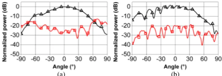
The radiation patterns and gain for the H=200µm (nominal) and H=575µm (inflated) configurations have been measured in a far-field millimeter-wave anechoic chamber using a V-type connector and a WR-15 waveguide-to-coaxial transition covered with absorbers. The antenna is inflated using a 1-ml syringe. The radiation patterns are represented in Figs. 9 and 10, respectively.
(a) (b)
Fig. 9. Measured radiation patterns of the flat antenna (around H=200µm) at 55 GHz. (a) H-plane, (b) E-plane. : Co-polarization component. : Cross-polarization component.
(a) (b)
Fig.10. Measured radiation patterns of the inflated antenna (around H=575 µm) at 50 GHz. (a) H-plane, (b) E-plane. : Co-polarization component.
: Cross-polarization component.
The pronounced ripples observed in E-plane are due to reflection and diffraction effects on the V-type feed connector. For the flat case, the theoretical directivity and measured gain equal 9.45 dBi and 5.0 dBi, respectively, which corresponds to a 36% radiation efficiency. For the inflated position, the theoretical directivity is 8.65 dBi, the measured gain is 4.5 dBi and the corresponding efficiency is η=39%. Thus, there is no significant change of the antenna radiation for inflated positions. The relatively low radiation efficiency can be explained by the 1-cm long feed line part printed on bulk PDMS (Figs 3a and 3b, [13]) where about 2.5 dB losses occur.
V. DISCUSSION
In this work, within the considered height variation, the membrane deformation is far from the 160% elongation failure of PDMS. The height variation could be increased, and therefore the frequency agility, but at the expense of the impedance performance. For severe deformations, metal patterns are more likely to fail. This problem can be avoided using liquid metal [14, 15] (but with higher metallic losses) or using meandered metal patterns. Fatigue studies on the gold metal patterns (especially the flexion at the bulk PDMS to membrane transition) have to be carried out to determine the long term system reliability.
In this letter, only quasi-static reconfiguration using a syringe pump is demonstrated. Tuning speed and integration can be addressed by implementing actuators with higher dynamics. Reconfiguration speed of 50-100 ms can be expected. To better control the height and thus the resonant frequency of the antenna, piezoresistive gauges with feedback on the actuators can be integrated.
VI. CONCLUSION
We demonstrated the frequency tuning of microstrip antennas printed on ultra flexible PDMS membranes using pneumatic actuation. Mechanical reconfiguration enables avoiding the use of active devices that may face cost, losses and complexity issues at millimeter waves. The antenna tunability reaches 8.2% between 55.35 GHz and 51 GHz for a 287% variation of the patch height between H=200µm and
H=575µm, which is beyond the state of the art for
mechanically tuned antennas in this frequency range. Bandwidth, radiation patterns and gain remain fully acceptable within the displacement range. This result using a very low
may be extended to even higher frequencies without significant change. Future works include implementation of integrated actuators and structural control elements on the antenna [17].
ACKNOWLEDGMENT
The authors would like to thank the IEMN and IETR technical staff (L. Le Coq) for the experimental characterization in impedance and radiation, respectively, as well as F. Lapierre, E. Algre and B. Legrand at IEMN for valuable advices.
REFERENCES
[1] J. T. Bernhard, “Reconfigurable antennas,” Encyclopedia of RF and Microwave Engineering, Ed. K Chang (New York:Wiley), 2005. [2] Z. Jin and A. Mortazawi, “An L-band tunable microstrip antenna using
multiple varactors,” IEEE Antennas and Propag. Soc. Int. Symp., vol. 4, pp. 524–527, 2003.
[3] H. Jiang, M. Patterson, C. Zhang, and G. Subramanyam, “Frequency agile microstrip patch antenna using ferroelectric thin film varactor technology,” IEEE Antennas and Propag. Soc. Int. Symp. APS-URSI'09, 2009.
[4] L. Le Garrec, R. Sauleau, and M. Himdi, “A 2:1 band frequency-agile active microstrip patch antenna,” Second European Conference on
Antennas and Propagation, EuCAP 2007, 2007.
[5] K.-F. Lee, K. Ho, and J. Dahele, “Circular-disk microstrip antenna with an air gap,” IEEE Trans. Antennas and Propag., vol. 32, no. 8, pp. 880–884, 1984.
[6] J.-C. Langer, J. Zou, C. Liu, and J. Bernhard, “Micromachined reconfigurable out-of-plane microstrip patch antenna using plastic deformation magnetic actuation,” IEEE Microw. Wireless Compon.
Lett., vol. 13, no. 3, pp. 120–122, 2003.
[7] E. Erdil, K. Topalli, M. Unlu, O. Civi, and T. Akin, “Frequency tunable microstrip patch antenna using RF MEMS technology,” IEEE Trans.
Antennas Propag., vol. 55, no. 4, pp. 1193–1196, 2007
[8] R. Al-Dahleh, C. Shafai, and L. Shafai, “Frequency-agile microstrip patch antenna using a reconfigurable mems ground plane,” Microwave
and Optical Technology Letters, vol. 43, no. 1, pp. 64–67, 2004.
[9] R. Jackson and R. Ramadoss, “A MEMS-based electrostatically tunable circular microstrip patch antenna,” J. Micromech. Microeng., vol. 17, no. 1, pp. 1–8, 2007.
[10] H. Kang and J. Song, “Electrically tunable rectangular microstrip antenna,” Electron. Lett., vol. 46, no. 1, pp. 18-19, Jan. 2010. [11] N. Tiercelin, P. Coquet, R. Sauleau, V. Senez, and H. Fujita,
“PolyDiMethylSiloxane membranes for millimeter-wave planar ultra flexible antennas,” J. Micromech. Microeng., vol. 16, pp. 2389–2395, 2006.
[12] S. Hage-Ali, N. Tiercelin, P. Coquet, R. Sauleau, V. Preobrazhensky, and P. Pernod, “Millimeter-wave patch array antenna on ultra flexible micromachined Polydimethylsiloxane (PDMS) substrate,” IEEE
Antennas and Propag. Soc. Int. Symp. APS-URSI'09, 2009.
[13] S. Hage-Ali, N. Tiercelin, P. Coquet, R. Sauleau, H. Fujita, V. Preobrazhensky, and P. Pernod, “A millimeter-wave microstrip antenna array on ultra-flexible micromachined polydimethylsiloxane (PDMS) polymer,” IEEE Antennas Wireless Propag. Lett., vol. 8, pp. 1306– 1309, 2009.
[14] J.-H. So, J. Thelen, A. Qusba, G. J. Hayes, G. Lazzi, and M. D. Dickey, “Reversibly deformable and mechanically tunable fluidic antennas, ”
Adv. Funct. Mater., vol. 19, no. 22, pp. 3632–3637, 2009.
[15] M. Kubo, X. Li, C. Kim, M. Hashimoto, B. J. Wiley, D. Ham, and G. M. Whitesides, “Stretchable microfluidic radiofrequency antennas,”
Adv. Mater., vol. 22, no. 25, pp. 2749–2752, 2010.
[16] C. A. Balanis, Antenna theory: Analysis and design, 3rd Edition, Wiley, Hoboken, 2005.
[17] S. Hage-Ali, N. Tiercelin , P. Coquet, R. Sauleau, V. Preobrazhensky, and P. Pernod, “Dispositif hyperfréquences reconfigurable à membrane déformable,” Patent (pending) FR-10/00166, 15 Jan. 2010