HAL Id: hal-00630261
https://hal.archives-ouvertes.fr/hal-00630261
Submitted on 10 Oct 2011
HAL is a multi-disciplinary open access
archive for the deposit and dissemination of
sci-entific research documents, whether they are
pub-lished or not. The documents may come from
teaching and research institutions in France or
abroad, or from public or private research centers.
L’archive ouverte pluridisciplinaire HAL, est
destinée au dépôt et à la diffusion de documents
scientifiques de niveau recherche, publiés ou non,
émanant des établissements d’enseignement et de
recherche français ou étrangers, des laboratoires
publics ou privés.
RFID service for non-RFID enabled devices: Embedded
hardware implementation
Oscar Botero, Hakima Chaouchi
To cite this version:
Oscar Botero, Hakima Chaouchi. RFID service for non-RFID enabled devices: Embedded hardware
implementation. The 2nd International Conference on Ambient Systems, Networks and Technologies
(ANT), 2011, pp.2011. �hal-00630261�
RFID service for non-RFID enabled devices
Embedded hardware implementation
Oscar Botero and Hakima Chaouchi
CNRS SAMOVAR, UMR 5157. Telecom SudParis, Evry, France {oscar.botero, hakima.chaouchi}@it-sudparis.eu
Abstract— Radio Frequency Identification (RFID) applications require the use of specialized hardware in order to obtain the IDs that are provided by the tags. This condition limits the extension of the information to devices with non-RFID capabilities. In this paper we present the design and implementation of a RFID service conceived for devices with non-RFID hardware but a WLAN interface. More specifically, we utilized embedded hardware to build an affordable and practical device that allows obtaining lists of tag IDs by using a common WLAN interface. Additionally, we performed delay metrics experiments and measurements are provided.
Keywords: Embedded hardware; Radio Frequency
Identification; WLAN.
I. INTRODUCTION
RFID technology provides an information platform that allows tracking and tracing persons, animals and items extending the limitations of the barcode due to the non-line of sight detection requirements as well as the general reduced device size. The basic architecture is constituted by Interrogators or Readers, Tags and Middleware. The tags provide an Identification number (ID) that is linked to the object of interest. The Readers perform the ID collection from the deployed tags and transmit that information to the Middleware in order to accomplish certain purpose or application [1, 2 and 3].
RFID systems required specialized hardware in order to access to the information they provide. However, this condition limits the extensibility of applications to devices that do not have available RFID hardware. To overcome this barrier integration platforms can be implemented [4].
In order to propose an integration platform we need to consider common points that will allow the information flow. In this paper we propose the design and implementation of a system that provides the tag IDs gathered by a RFID reader to any device that has a common wireless interface, overriding the necessity of having a RFID-enabled device at the user's side.
We focused on the implementation of the solution by using embedded hardware due to the reduced costs, flexibility and versatility.
There are different technologies that allow wireless
communications like ZigBee, Bluetooth, Wimax, etc. However, we selected Wi-Fi as the common denominator due to the popularity of those protocols, the huge number of portable devices Wi-Fi enabled [5] and the coverage range, thus a service based on RFID information can be extended to common devices like mobile phones, pads and laptops. On the other hand, the hardware used it is open to add other wireless devices that uses the aforementioned technologies.
There are some related work oriented to the implementation of RFID systems by using embedded hardware to provide different services and applications. In [6] a Location Aware service is implemented based on an embedded RFID platform. In [7] a system to perform vehicular monitoring is implemented by combining RFID, GPS and GSM modules with a microcontroller as the coordinator and processor unit. In this way a tracking system can be put into practice for vehicular uses. The integration of RFID and Wireless Sensor Networks (WSN) by using embedded hardware can be seen in [8]. Basically, in that proposal a RFID and a RF transceiver are bind to a microcontroller in order to provide warehouse management services. In [9] an architecture and hardware implementation of an Access Control system is presented. It uses embedded hardware and shows a modular architecture approach. In [10] a verification and validation system is developed based on a microprocessor in order to reduce cost and provide easy maintaining.
Our contribution proposes the extension of the information provided by the RFID tags to users that have no RFID hardware available but a WLAN (Wireless Local Area Network) interface. We orchestrate the control and information delivery by using a microcontroller as the core element and different modules that provide RFID detection and wireless connectivity. Additionally, we measured delay metrics and we provide application scenarios of the system developed.
The rest of the paper is organized as follows. Section II describes the generic system architecture followed by section III where the hardware and software implementation is depicted. In section IV we provide the results of the measurement performed. In section V two application examples are presented and finally the paper concludes in section VI.
II. SYSTEM ARCHITECTURE A. Overview
Our solution can be defined as a proxy that transmits the RFID tag IDs to users connected by the WLAN interface. On this way they do not need to have embedded RFID hardware to obtain the information provided by the RFID deployment but a WLAN interface, or any other interface commonly agreed.
Regarding the implementation, we rely on a microcontroller as the center of the system and different hardware modules that perform specific tasks. In Fig. 1 we present the basic modular structure of the system and in section B we explain the generic components.
Fig. 1. Block Diagram of the System.
B. Modules
There are four basic modules that constitute the system. These are described as follows.
1) Microcontroller (MC)
The MC provides the control and coordination of the different modules in the system. This device should provide enough memory space to hold the controlling algorithm as well as enough ports to branch the different modules. They will perform specific functions like RFID reading, external memory and the wireless interface among others.
2) RFID Reader
It performs the scanning or detection of the RFID tag IDs that are going to be transmitted to the users that request them via the wireless interface.
3) External Memory
Microcontrollers are limited by the memory they normally provide. For this reason we require external storage space in order to record the tag IDs detected by the RFID module.
4) Wireless Interface
This module is the common bridge to the users with non-RFID embedded hardware and the service that will provide the list of RFID tags detected.
III. IMPLEMENTATION A. Overview
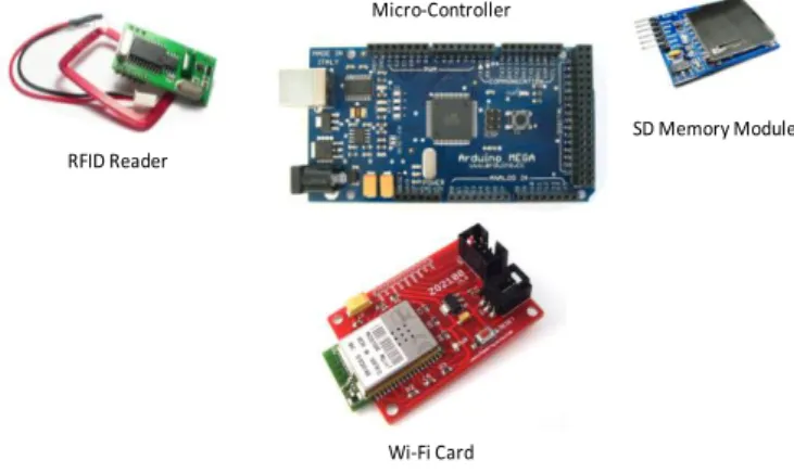
We implemented the proxy solution by using commercially available modules (Fig. 2). A microcontroller is the core of the system and it provides enough ports, memory and processing
power required to this implementation. We added three modules that perform the RFID detection, external memory space and WLAN interface respectively. The description of all these elements is provided as follows.
B. Modules
1) Microcontroller (MC)
We base our solution on the affordable and versatile Atmel 1280 microcontroller [10]. It provides an 8-bits-16MHz core with 128KBytes of flash memory, 8 Kb SRAM, 4 Kb EEPROM, 54 digital ports, 16 analog ports, I2C, SPI, Serial ports and operates between 2.7 and 5.5 volts. A commercial board provided by Arduino [12] provides an USB programming interface and several open source libraries in C-like code. We remark that any other microcontroller or embedded board that provides enough resources to implement the system can be used.
Fig. 2. Hardware Modules used. 2) RFID Reader
The RFID module is a Low Frequency (LF) Wiegand interface device [13]. Wiegand uses 26 bits format where 24 bits are user data (Tag ID) and 2 bit are used as parity.
The decoding time is less than 100 ms with a maximum effective distance up to 150 mm. It can read passive RFID tags that comply with the EM4100 standard. It uses two digital ports connection in the MC in order to transmit the detected tag ID. For this implementation the tag IDs are limited to 24 bits due to the limitations of the module however other RFID readers can be used to implement different standards and have longer IDs.
3) External Memory
If the MC is powered off the information that is not saved in the ROM will be lost. Due to the reduced amount of memory available (4Kb) we included an external storage module. It is basically a SD (Secure Digital) card unit that allows us to store the tag IDs that had been obtained through the RFID reader module. We can provide up to 16GBytes of external storage by using a standard SD card. This module is connected to the MC by using a SPI (Serial Peripheral Interface Bus) interface.
SD Memory Module Micro-Controller
Wi-Fi Card RFID Reader
Micro-Controller
External Memory InterfaceWireless RFID Reader
There are available FAT (File Allocation Table) libraries to read, write and edit the log files recorded.
4) Wireless Interface
We employed a 2.4 GHz, low power 802.11 a/b compliant module [14]. It provides WLAN connectivity up to 2Mbps. It can be setup in Infrastructure or Ad hoc modes and supports open, WEP (Wired Equivalent Privacy), WPA and WPA2 (Wi-Fi Protected Access II) methods. This unit also uses the SPI port of the MC
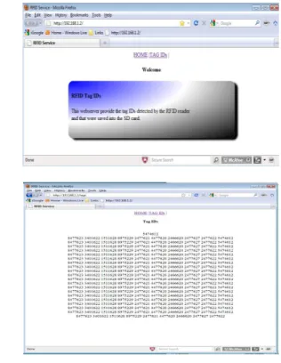
In order to provide the list of tags to the users we create a basic web server that provides via HTML the list of gathered tags by the RFID readers. In this way users with a WLAN interface can connect to the ad hoc network set up by the system and obtain the list of available tags. (Fig. 3)
Fig. 3. Web server. 5) RFID Tags
We used Standard EM4100 compliant RFID passive tags (Fig. 4). Due to the characteristics of the RFID reader we employed it can detect 24 bits of the tag ID.
Fig. 4. RFID passive tags.
C. Flow Diagram
The proposed system performs the following processes in order to provide the tag IDS to users. At first, the system executes the Initialization phase where all the modules run certain routines to make their resources and functionalities available. The WLAN module is activated and the initial page is loaded thus it is ready to be displayed when the requests arrive. After that, the SD module is initialized providing access to the card in order to read and write information. Later, the routine that starts the RFID reader runs. At this step the port interruption is assigned in the MC in order to detect the pulses transitions that identify the bits in the RFID tag.
Once the Initialization process ends, the system is ready to deal with two types of events, either RFID tag detection or a WLAN user request.
If a tag is detected the MC sends the ID to the SD card and updates the information that will be published in the web site that the web server manages.
If a user connects to the server, it will send a webpage that includes the list of detected tags that are stored into the SD card. On this way the user can get the IDs of the tags without requiring a RFID reader but a WLAN interface. The server runs in ad hoc mode and different security methods can be implemented (open, WEP, WPA). The processes flow chart is presented in the following figure (Fig. 5)
Fig. 5. Processes.
IV. EXPERIMENT AND RESULTS
We measured the delay incurred while initializing the different modules. In this way we can obtain the total time require for the system to perform this phase. Secondly, we
Initiate WLAN Start Initiate SD Card Initiate RFID Reader Devices Initialization RFID detected ? yes Save Tag ID to SD Card Update Web Server Data Request to Web Server ?
Send Tag IDs via website
measured the transmission delay of the tag IDs to a user connected via the WLAN interface.
A. Initialization Delay
In this section we present the initialization delay of the modules used.
1) WLAN Module
In table I we show the average time required for the WLAN module to be fully functional.
TABLE I. WLAN Initialization Delay.
2) SD Module
In table II we present the average time required for the SD module in order to be ready to read and write files into the SD memory card.
TABLE II. SD Initialization Delay.
3) RFID Module
Finally, in table III we show the average time required for the RFID module to be functional and ready to detect tag IDs.
TABLE III. RFID Initialization Delay.
The Total Initialization Delay (TID) can be calculated by using linear Equation (1).
TID = WLANDelay + SDDelay + RFIDDelay (1)
The average TID is about 21.47 seconds where the WLAN module is the biggest contributor due to the complexity of the module and the setting up of different mechanisms that it requires in order to operate.
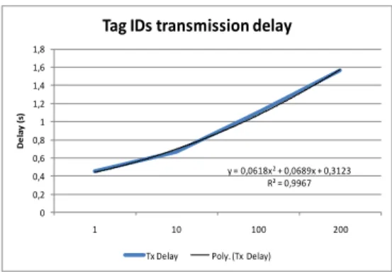
B. RFID Tag IDs Transmission Delay
We conducted a test by using the software protocol analyzer Wireshark [15] in order to measure the time a user needs to wait in order to get the list of available tag IDs.
The results are presented in the next figure (Fig. 6) and in the Table IV.
Fig. 6. Tag IDs transmission Delay. TABLE IV. Tag IDs transmission Delay.
We measured from 1 to 200 tag IDs and for the maximum value we obtain a delay of approximately 1.6 seconds.
V. APPLICATIONS
In this section we present two applications based on the implemented system.
A. Building Access Log
We can implement a Building Access Register by detecting the tag IDs of the persons who access the building. Additionally, we can add an external clock reference provided for example by the DS1307 from Maxim [16] in order to track the date and time of the access. We used an I2C (Inter-Integrated Circuit) module that allows us to obtain an external clock reference driven by a crystal and battery backup (Fig. 7). The log file is available via the WLAN connection.
Fig. 7. External Clock Reference Module.
The block diagram is shown in Fig. 8. The way it works is similar to the basic configuration stated before but what changes is that every time a tag is registered by the RFID reader, it is saved into the SD card adding up the current date. The Web Server will be updated afterwards thus the current tag list is available to the users that require that information.
Fig. 8. Block Diagram of the System.
Average (s) 21.09 Standard Deviation 0.72 Confidence Interval 0.15 Average (s) 0.3476 Standard Deviation 0.0005 Confidence Interval 0.0001 Average (s) 0.037 Standard Deviation 0.000 Confidence Interval 0.000 y = 0,0618x2+ 0,0689x + 0,3123 R² = 0,9967 0 0,2 0,4 0,6 0,8 1 1,2 1,4 1,6 1,8 1 10 100 200 D e la y (s )
Tag IDs transmission delay
Tx Delay Poly. (Tx Delay)
Number of Tags 1 10 100 200
Average Time (s) 0.45 0.66 1.11 1.57
Standard Deviation 0.01 0.01 0.02 0.01
Confidence Interval 0.0015 0.0015 0.0035 0.0029
Micro-Controller
External Memory InterfaceWireless RFID Reader
External Clock Reference
B. RFID-WSN (Wireless Sensor Networks)
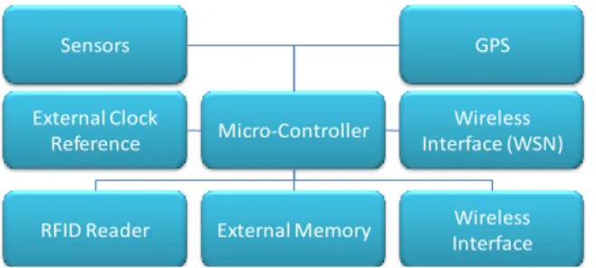
The basic configuration of the system can be expanded by adding other modules to provide connectivity for a WSN. In this manner data from sensors and RFID can be combined to provide an information platform and that does not require, at the user side, the use of specialized hardware to obtain the data. A commercial XBee module can be included to allow ZigBee connectivity [17] (Fig. 9)
Fig. 9. ZigBee Module.
In Fig.10 we present a general block diagram where data collected from sensors, GPS and other modules can be combined to provide an information and integration platform.
Fig. 10. Block Diagram of the System.
VI. CONCLUSION AND FUTURE WORK
In this paper we provide the design and implementation of a RFID information service that provide tag IDs to users connected via a wireless interface. For certain applications this system provides an integration platform into the RFID networks for devices that have no suitable hardware (RFID Reader). Due to the modularity of the system more features and capabilities can be implemented to extend it use to diverse applications and requirements, i.e. Wireless Sensor Networks. A future work path would include experiments with a network of MC to explore limitations and capabilities as well as other devices like micro-computers.
REFERENCES
[1] Wiebking L., Metz G., Korpela M., Nikkanen M, Penttila K., A Roadmap for RFID Applications and Technologies, Published on Internet by "Coordinating European Efforts for Promoting the European RFID Value Chain" (CE RFID). August 12, 2008. http://www.rfid-in-action.eu/public/results
[2] K. Finkenzeller. RFID handbook - Second Edition. JOHN WILEYSONS, 195–219, 2003.
[3] Chaouchi Hakima, the Internet of Things: Connecting Objects, Wiley-ISTE, 2010.Chapter 5 by Oscar Botero and Hakima Chaouchi. [4] Botero, O.; Chaouchi, H.; , "Peer-to-Peer Framework for
RFID/Non-RFID Reader-Enabled Users," Green Computing and Communications
(GreenCom), 2010 IEEE/ACM Int'l Conference on & Int'l Conference on Cyber, Physical and Social Computing (CPSCom) , vol., no.,
pp.500-504,18-20.Dec.2010.
[5] Steve Smith, Wi-Fi enabled mobile phone handsets in the US, 2010-2015, Coda research Consultancy, February 2010.
[6] Ming-Shen Jian; Shu Hui Hsu; , "Location Aware Public/Personal Diversity of Information Services based on embedded RFID Platform," Advanced Communication Technology, 2009. ICACT 2009.
11th International Conference on , vol.02, no., pp.1145-1150, 15-18
Feb.2009.
[7] Huiping Li; Yi Zhou; Lu Tian; Chunlin Wan; , "Design of a Hybrid RFID/GPS-Based Terminal System in Vehicular Communications," Wireless Communications Networking and Mobile
Computing (WiCOM), 2010 6th International Conference on , vol., no.,
pp.1-4,23-25.Sept.2010.
[8] Zhou Xiaoguang; Long Wei; "The research of network architecture in warehouse management system based on RFID and WSN integration," Automation and Logistics, 2008. ICAL 2008. IEEE
International Conference on , vol., no., pp.2556-2560, 1-3 Sept. 2008
[9] An Embedded System and an Architecture for Access Control and Access Management
[10] Verification and Validation Communication Layer of Embedded Smart Card System. [11] http://www.atmel.com/dyn/products/product_card.asp?part_id=3633 [12] http://arduino.cc/en/Main/ArduinoBoardMega [13] http://en.wikipedia.org/wiki/Wiegand_interface [14] http://ww1.microchip.com/downloads/en/DeviceDoc/70624A.pdf [15] http://www.wireshark.org/ [16] http://www.maxim-ic.com/datasheet/index.mvp/id/2688 [17] http://www.digi.com/products/wireless-wired-embedded- solutions/zigbee-rf-modules/point-multipoint-rfmodules/xbee-series1-module.jsp#overview Micro-Controller
External Memory Wireless Interface RFID Reader External Clock Reference Wireless Interface (WSN) Sensors GPS