1
N° d’ordre: 2898
Doctoral Thesis
Discipline: Physics of Materials
Sub-discipline: Condensed Matter Physics
Nano-Coating of CSP Reflectors: A Step towards the Creation of a
Self-Cleaning Effect
A thesis presented by: Houda ENNACERI
22
ndJuly 2016
In Front of the Jury:
President:
Hamid EZ-ZAHRAOUY PES, Faculty of Sciences, Mohammed V University,Rabat.
Examination Committee:
Abdallah EL KENZ PES, Faculty of Sciences, Mohammed V University,Rabat. Abdelhafed TALEB PES, PSL Research University, Chimie ParisTech - CNRS,
Institut de Recherche de Chimie Paris, and Université Pierre et Marie Curie, Paris.
Abdelilah BENYOUSSEF PES, Resident member of Hassan II Academy of Science and Technology, Rabat.
Ahmed ENNAOUI PES, Qatar Environment and Energy Research Institute (QEERI), and Hamad bin Khalifa University (HBKU), Doha, Qatar.
Asmae KHALDOUN PA, School of Science and Engineering, Al Akhawayn University, Ifrane.
Invited:
Badr IKKEN General Director of IRESEN (Institut de Recherche en Energie Solaire et Energies Nouvelles), Rabat.
Faculty of Sciences, 4 Avenue Ibn Battouta B.P. 1014 RP, Rabat – Morocco Tel +212 (0) 5 37 77 18 34/35/38, Fax: +212 (0) 5 37 77 42 61, http://www.fsr.ac.ma
2 To my parents, my husband, and the joy of my life: my son Mohamed Othmane SADAOUI
3
Acknowledgments
The work presented in this dissertation was directed and supervised by of Prof. Abdallah EL KENZ (PES) and Prof. Abdelilah BENYOUSSEF (PES) from Mohammed V University, faculty of sciences, within the Laboratory of Magnetism and Physics of High Energies (LMPHE), under the co-supervision of Dr. Asmae KHALDOUN (PA) from the School of Science and Engineering (SSE) at Al Akhawayn University, and with close collaboration of Prof. Ahmed ENNAOUI (PES) from the Helmholtz Zentrum Berlin für Materialien und Energie (HZB-Berlin), the Qatar Environment and Energy Research Institute (QEERI), and Hamad bin Khalifa University (HBKU), Doha, Qatar.
This research was financially supported by IRESEN (Institut de Recherche en Energie Solaire et Energies Nouvelles) within the framework of the InnoTherm II call of projects, and partially supported by the Deutscher Akademischer Austauschdienst (DAAD).
First of all, I wish to thank Prof. Hamid EZZAHRAOUY from LMPHE for doing me the honor of acting as the jury president of the PhD defense, and for reading and writing a report about my thesis.
I am deeply thankful to my supervisor Prof. Abdallah EL KENZ (PES), for accepting me within the Laboratory of Magnetism and Physics of High Energies (LMPHE), for all the guidance, encouragements and in-depth discussions throughout the 3 years of my PhD research, and also for writing a report about this work.
I would like to thank Prof. Abdelhafed TALEB (PES), for his wonderful collaboration, and for welcoming me into his research group in Paris. It was a pleasure working with him, his engagement, expertise and technical support have been invaluable for the progress of this work. I want also to thank him for accepting to write a report about my work.
I have very much enjoyed working with Prof. Abdelilah BENYOUSSEF (PES), to whom I owe my sincere gratefulness for his time, for the long and constructive discussions and technical support.
The experimental part of this work has been conducted at the helmholtz zentrum berlin für
4
ENNAOUI (PES). I am wholeheartedly thankful to Prof. Ahmed ENNAOUI, for his continuous guidance, for welcoming me into his research group at the HZB, and for his rigorous technical discussions and scientific ideas.
My deepest gratitude goes to Dr. Asmae KHALDOUN (PA), for believing in me and supporting me since the beginning, for generously dedicating so much of her time, and for her encouragement, step-by-step assistance which made this project a successful and inspiring learning experience.
Great thanks go to IRESEN (Institut de Recharche en Energie Solaire et Energies Nouvelles), for financially supporting this research in the framework of the InnoTherm II project “Nano Coating and Testing: a step towards the improvement of CSP reflectors for less intensive maintenance both in terms of labor and water” and to Mr. Badr IKKEN, general director of IRESEN, for his successful collaboration and for honoring me by taking part of the PhD jury members.
From the Helmholtz Zentrum Berlin, I would like to thank Prof. Martha LUX-STEINER, Dr. Reiner KLENK, Dr. Jaison KAVALAKKATT, Dr. Lin XIANZHONG, Mr. Tristan KÖHLER, Dr. Rodrigo SAEZ-ARAOZ, Mr. Lan WANG, Ms. Darja ERFURT and Mr. Harbauer KARSTEN for their continuous help and support during my scientific stays at the HZB.
I am also thankful to the DAAD (Deutscher Akademischer Austauschdienst) for partially supporting my PhD research.
Moreover, I would also like to acknowledge MASEN and GIZ, for granting me the participation in the enerMENA internship on Concentrated Solar Power at the Plataforma Solar de Almeria (PSA) in 2013, and I would like to thank the scientists and trainers from El Centro de Investigaciones Energéticas, Medioambientales y Tecnológicas (CIEMAT) and from the German Aerospace Center (DLR) for their time and valuable presentations.
Furthermore, I want to express my sincere love and gratitude to my parents, my husband and my adorable son, for their endless love and for supporting me in every single step of my career.
5
Abstract
In this work, high quality, transparent multifunctional and smart coatings (Al2O3, TiO2 and ZnO)
used as top protective layers for CSP reflectors are studied. The Al2O3, TiO2 and ZnO
top-coatings are deposited using the Ion Layer Gas Reaction (Spray-ILGAR) technique which was demonstrated to be an interesting way to prepare homogeneous thin films with different morphologies. Also, it is shown that the deposition of the suggested top-coatings using the ILGAR technique conserves a very good specular reflectance of the mirrors (94% reflectance in the Near Infrared range).
The thickness effect on the optical, morphological and wetting properties of TiO2 and ZnO thin
films was first studied experimentally, and the respective results were confirmed by first principle ab initio calculations. The variation in the optical band gap was explained by increasing oxygen vacancy with the film thickness for TiO2 thin films, and by the contribution of
compressive strain in the c-direction for ZnO thin films.
It is shown that Al2O3 top-protective layer deposition by Spray-ILGAR technique increases the
surface hydrophobicity without altering the optical properties of the CSP reflectors. Moreover, the photocatalytic activity of the prepared TiO2 and ZnO top coatings is evaluated and reported.
Furthermore, the effect of post-annealing treatment on the photocatalytic degradation of the top-coatings is pointed out, and is explained in terms of crystallinity and surface morphology. The increase of the photocatalytic activity and/or surface super-hydrophobicity can be achieved by increasing surface roughness, which is a conflicting requirement with optical transparency needed for concentrated solar power (CSP) top-coating application. Also, it is pointed out that TiO2 and ZnO top protective thin films exhibit a photo-induced switching of their wetting
properties only after 30 min of UV exposure, and their usability as multifunctional top-protective layers for CSP application is discussed.
Key words:
Concentrated Solar Power, Specular Reflectance, Multifunctional Coatings, Photocatalyis, Thin Films, Hydrophobicity/Hydrophilicity, Al2O3, TiO2, ZnO.
6
Résumé
Ce travail étudie l’application de différents revêtements multifonctionnels transparents et de haute qualité, à savoir; l’oxyde d’alumine (Al2O3), le dioxyde de titane (TiO2) et l’oxyde de zinc
(ZnO), comme couches protectrices des réflecteurs solaires CSP. Les nano- revêtements d’Al2O3, TiO2 et ZnO sont déposés par la technique Spray-ILGAR, qui assure la préparation de
différentes couches minces homogènes avec des morphologies différentes. En outre, il est démontré que le dépôt des revêtements proposés dans ce travail par la technique ILGAR conserve une très haute réflexion spéculaire des miroirs (94% de réflectance dans le proche infrarouge).
L'effet de l'épaisseur sur les propriétés optiques, morphologiques et les propriétés de mouillage des couches minces de TiO2 et de ZnO a d'abord été étudié expérimentalement, et les résultats
ont été confirmés par les calculs ab initio. De plus, la variation de la largeur de bande optique est expliquée par l'augmentation de lacunes d'oxygène avec l'épaisseur pour les couches TiO2, et par
la contribution de la contrainte de compression dans la direction c pour les couches ZnO.
Ce travail montre que le dépôt de couches protectrices d’Al2O3 par la technique Spray-ILGAR
augmente l'hydrophobie de la surface des réflecteurs CSP sans altérer leurs propriétés optiques. En outre, l'activité photo catalytique des revêtements TiO2 et ZnO est évaluée, et l'effet du recuit
thermique sur l’activité photo catalytique est souligné et expliqué en termes de cristallinité et de morphologie de surface. L'augmentation de l'activité photo catalytique et / ou de super-hydrophobie de surface peut être obtenue en augmentant la rugosité de surface, ce qui en contrepartie, entraine une diminution de la transparence optique nécessaire pour l’application CSP. De plus, il est souligné que les couches minces TiO2 et ZnO montrent un comportement de
commutation de leurs propriétés de mouillage photo-induites seulement après 30 min d'exposition aux UV. L’utilisation des couches minces multifonctionnelles proposées dans ce travail dans l'application CSP est discutée.
Mots Clés:
Solaire Thermique à Concentration, Réflectance Spéculaire, Revêtements Multifonctionnels, Photocatalyse, Couches Minces, Hydrophobie/Hydrophilie, Al2O3, TiO2, ZnO.
7
Résumé Détaillé
Pour le solaire thermique a concentration (CSP), les régions désertiques sont considérées comme étant les plus appropriées pour les installations CSP, principalement en raison de leur grand ensoleillement normal direct (DNI). Cependant, cet environnement d'exploitation conduit à une exposition à des conditions météorologiques très dures, comme un fort flux d'irradiation, des tempêtes de vent et des tempêtes de sable ou de poussière. Ces facteurs de dégradation peuvent sérieusement affecter la durabilité des réflecteurs solaires, entraînant une diminution drastique de leur réflectance spéculaire, et entrainant une diminution de l'efficacité des centrales CSP. Par conséquent, des revêtements protecteurs sont nécessaires pour l’amélioration de la performance et de la durabilité des réflecteurs CSP, qui sont sérieusement affectés par différents facteurs de dégradation tels que l’abrasion, l’oxydation, la corrosion et les salissures, etc…
Pour le pas altérer la réflectance spéculaire des réflecteurs solaires, le développement de matériaux candidats hautement transparents est d'un grand intérêt. Les revêtements de matériaux candidats sont exposés à différentes conditions, qui nécessitent des propriétés différentes telles que transparence, auto-nettoyage, anticorrosion, anti-salissures etc. Habituellement, ces propriétés sont des exigences pour lesquelles un équilibre est nécessaire pour optimiser les fonctions de revêtement dans les conditions extérieures. Par exemple, une augmentation de la rugosité de surface peut augmenter la superhydrophilie ainsi que l'activité photo catalytique mais réduit la transparence due à des pertes par diffusion de la lumière. De plus, l'adhérence (stabilité) et la rugosité présentent aussi un conflit. Une augmentation de la résistance de liaison du revêtement au substrat pourrait améliorer sa robustesse mais réduit sa rugosité. Par conséquent, un contrôle approprié de la rugosité de surface est nécessaire pour optimiser toutes les propriétés mentionnées. En outre, pour certains environnements d'exploitation, les conditions de travail des matériaux changent au cours de leur durée de vie, d'où la nécessité urgente de concevoir des revêtements de matériaux intelligents dont les propriétés pourraient changer de manière contrôlée par rapport aux paramètres de l'environnement de fonctionnement. En outre, pour une mise en œuvre industrielle, le revêtement doit être facilement fabriqué, à faible coût et doit présenter une stabilité suffisante.
Les recherches menées par diverses institutions de recherche et de développement dans le domaine CSP telles que NREL, CIEMAT et DLR se convergent dans le développement de miroirs hautement réfléchissants avec une meilleure durabilité et performance. Parmi les
8
revêtements rapportés et publiés dans la littérature figurent TiO2, Al2O3 et SiO2. Bien que le
développement de revêtements autonettoyants présente un grand intérêt pour l'application CSP, l'activité photo catalytique des réflecteurs CSP n'est pas rapportée dans la littérature. En outre, l’utilisation de ZnO comme revêtement supérieur pour les réflecteurs CSP n’est pas non plus rapporté.
Ce travail étudie les propriétés optiques, morphologiques et autonettoyantes de différentes couches minces multifonctionnelles de TiO2, ZnO et Al2O3 avec des propriétés optimisées. Le
dépôt de ces films est effectué par la technique Spray-ILGAR (Ion Layer Gas Reaction), qui est un dépôt simple et peu coûteux, équivalent à un dépôt chimique en phase vapeur assisté par aérosol (AACVD). Cette méthode produit des couches minces hautement transparentes avec une homogénéité élevée. Le procédé Spray-ILGAR a été précédemment utilisé pour déposer différents matériaux pour l'application photovoltaïque, et est utilisé pour la première fois dans ce travail pour l'application CSP solaire thermique.
Étant donné que les réflecteurs solaires sont exposés à la lumière solaire, qui contient environ 4% de la lumière UV, les couches protectrices de TiO2 et ZnO représentent un moyen efficace et
économique pour créer un effet autonettoyant en combinant l’activité photo catalytique ainsi que le comportement hydrophile/superhydrophile photo-induit.
Dans ce travail, il est montré qu'en contrôlant l'épaisseur du film, il est possible de contrôler les propriétés optiques. Dans le cas des couches minces de TiO2, l'écart observé entre le rapport
atomique O et Ti et la formule stœchiométrique de la phase anatase TiO2 est expliqué par les
changements morphologiques et l'augmentation des vacants d'oxygène avec l'épaisseur du film. De plus, pour les couches minces de ZnO déposées avec différentes épaisseurs, la variation de l’énergie de gap est expliquée par la contribution de la contrainte de compression dans la direction c. Ces deux résultats sont confirmés par les calculs ab initio. De plus, les films de TiO2
déposés par ILGAR sont intrinsèquement hydrophiles, et la transition du comportement hydrophile au comportement super hydrophile est mise en évidence lorsqu'une épaisseur de film critique est atteinte.
De plus, des surfaces super hydrophobes à base de films de ZnO structurés sont développées par dépôt électrochimique à basse température. La création d'une rugosité à double échelle est démontrée nécessaire pour obtenir un comportement super hydrophobe, avec un angle de contact de 157 °. En outre, les films préparés présentent une sensibilité élevée à la lumière UV, avec un
9
comportement de commutation induit par UV et un passage d’un comportement super hydrophobe à un comportement super hydrophile après seulement 30 minutes.
Il est démontré que les couches minces d’Al2O3, TiO2 et ZnO préparées en utilisant la technique
Spray-ILGAR se comportent comme des revêtements à la fois multifonctionnels et intelligents. Il est démontré que le dépôt de la couche protectrice d'oxyde d'aluminium Al2O3 augmente
l'hydrophobicité de surface avec un angle de contact de 100 ° sans altérer les propriétés optiques des réflecteurs CSP (réflectance spéculaire de 94%). De plus, les revêtements TiO2 et ZnO
présentent simultanément les propriétés suivantes: transparence, activité photo catalytique, et activité autonettoyante. Le traitement par recuit thermique a entraîné une amélioration de la cristallinité des films TiO2 et ZnO, mais on a observé un résultat différent sur leur activité photo
catalytique.
En fait, l'efficacité de photo dégradation du film de TiO2 après recuit a montré une légère
amélioration due à l'augmentation de la rugosité de surface, ce qui augmente la diffusion de la lumière et conduit à une diminution ultérieure de la transmittance optique. D'autre part, le traitement par recuit thermique de la couche de ZnO a conduit à un lissage de surface, favorable pour l’application CSP en raison de l'augmentation de la transmittance, mais non favorable pour la dégradation photo catalytique en raison de la réduction de la surface spécifique. Il est montré que la photo dégradation dépend de la rugosité de surface, ce qui affecte la transparence de surface. En outre, les couches minces préparées se comporteraient comme des revêtements autonettoyants dus à leurs propriétés photo catalytiques. En outre, on souligne un comportement de commutation de mouillabilité sous la lumière UV des revêtements TiO2 et ZnO. Toutes ces
caractéristiques rendent les revêtements proposés dans ce travail pratiques pour l’application CSP.
10 Table of Contents Acknowledgments... 3 Abstract ... 5 Résumé ... 6 Résumé Détaillé ... 7 I. Introduction ... 13
1. Thesis Overview and Motivation ... 14
2. Aims and Objectives ... 14
3. Structure of the Thesis ... 17
References ... 18
II. Thermodynamics of Self-Cleaning Coatings ... 20
1. Super-Hydrophobic Self-Cleaning Effect in Nature ... 21
2. Surface Energy ... 27
2.1. DLVO Theory... 27
2.2. Apolar Interactions (The Lifshitz-van der Waals (LW)) ... 29
2.3. Polar Interactions (The Lewis Acid-Base) ... 36
3. Van-Oss-Chaudhury-Good Approach for the Estimation of Surface Free Energy of Solids (Acid-Base Theory) ... 38
4. Surface Structure ... 40
4.1. Wetting Behavior on Smooth Surfaces ... 40
4.2. Wetting Behavior on Rough Surfaces ... 41
4.3. Contact Angle Hysteresis ... 43
References ... 44
III. Theoretical Background (ab initio Calculations) ... 49
1. The equation of Erwin Schrödinger ... 50
2. The Approximation of Born-Oppenheimer ... 54
3. The Slater Determinants ... 56
4. Hartree-Fock Approximation ... 57
5. Density Functional Theory ... 59
5.1. History ... 59
5.2. Thomas-Fermi Model ... 60
5.3. Thomas-Fermi-Dirac Model ... 61
5.4. Hohenberg-Kohn Theorems ... 62
5.5. Kohn-Sham Equations ... 65
5.6. Local Density Approximation (LDA) ... 66
5.7. Generalized Gradient Approximation (GGA) ... 68
5.8. Hybrid Functionals ... 70
5.9. Modified Becke-Johnson Potential (mBJ) ... 71
6. Comparison between Theoretical and Experimental Results ... 72
References ... 74
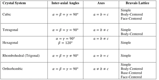
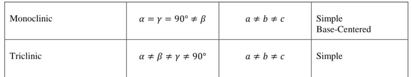
IV. Material Screening for Self-Cleaning Coatings ... 77
1. Aluminum Oxide ... 78
1.1. Aluminum Oxide Crystal Structure ... 78
1.2. Optical Properties ... 81
1.3. Aluminum Oxide Wettability ... 81
2. Titanium Dioxide (TiO2)... 83
11
2.2. Photo-catalysis of TiO2 under UV Irradiation ... 87
2.3. Wettability of TiO2 under UV Irradiation ... 92
2.4. TiO2 Surfaces with Special Wetting Regimes ... 94
3. Zinc Oxide (ZnO) ... 96
3.1. Zinc Oxide Crystal Structure ... 97
3.2. Photo-catalysis of ZnO under UV Irradiation ... 98
3.3. Wettability of ZnO under UV Irradiation ... 100
3.4. ZnO Surfaces with Special Wetting Regimes ... 102
References ... 103
V. Preparation of CSP Mirrors ... 112
1. Types of CSP Mirrors ... 113
1.1. Optical Characteristics of Reflectors ... 114
1.2. Types of Solar Mirrors in the Market ... 115
2. Preparation of Experimental CSP Mirrors ... 121
2.1. Materials and Methods ... 122
2.2. Spectrophotometric Measurements ... 122
2.3. Surface Morphology ... 125
2.4. Deposition of Top-Protective Coatings ... 127
References ... 129
VI. Deposition and Characterization of TiO2 Thin Films Prepared by Chemical Spray Pyrolysis Technique ... 131
1. Introduction ... 132
2. Experimental ... 134
2.1. Materials and Methods ... 134
2.2. TiO2 thin film deposition technique: Ion Layer Gas Reaction (Spray-ILGAR) ... 134
2.3. Thin film of TiO2 characterizations ... 135
3. Computational Method ... 135
4. Results and discussion ... 136
References ... 152
VII. Deposition and Characterization of ZnO Thin Films Prepared by Chemical Spray Pyrolysis Technique ... 156
1. Introduction ... 157
2. Experimental ... 157
2.1. Materials and Methods ... 157
2.2. ZnO thin film deposition technique: Ion Layer Gas Reaction (Spray-ILGAR) ... 158
3. Results and Discussion ... 158
3.1. XRD Analysis ... 158
3.2. Optical Properties of the Films ... 166
References ... 169
VIII. Fabrication of Water-Resistant Surfaces with Switchable Wetting Property using ZnO Structured Nanorod Arrays ... 171
1. Introduction ... 172
2. Experimental Details ... 174
2.1. Preparation of ZnO Nano rods ... 174
2.2. Preparation of ZnO thin film using reactive magnetron sputtering ... 175
2.3. Photo-catalysis Test ... 175
12
3. Results and Discussion ... 177
3.1. Surface Structure of ZnO nanorod arrays ... 177
3.2. Optical Measurements ... 182
3.3. Wetting Behavior under UV Illumination ... 182
3.4. Photo-catalysis Test ... 184
References ... 185
IX. Preparation of an Optically Transparent and Hydrophobic a-Al2O3 Protective Layer for CSP Reflectors ... 191
1. Introduction ... 192
2. Experimental Procedure ... 192
2.1. Materials and Methods ... 192
2.2. Film Characterization ... 193
3. Results and Discussion ... 193
References ... 198
X. Deposition of Multifunctional Top-Protective Coatings for CSP Reflectors ... 199
1. Candidate CSP Multifunctional Top-Coatings ... 200
2. Experimental ... 203
2.1. Materials and Methods ... 203
3. Results and discussion ... 206
3.1. X-Ray Diffraction Pattern ... 206
3.2. Optical Measurements ... 209
3.3. Surface Morphology ... 212
3.4. Wetting Behavior under UV Light ... 215
3.5. Photocatalysis Test ... 217
References ... 221
XI. Conclusion ... 226
General References ... 229
13
I. Introduction
14
1. Thesis Overview and Motivation
The aim of this thesis is the improvement of the quality of Concentrated Solar Power plants (CSP) by developing new coating materials that are lower in weight, more durable, energy efficient and more cost-effective. In addition of being highly transparent, the top-protective coatings proposed in this research have self-cleaning properties, which would reduce the need of maintenance while improving the mirrors efficiency.
2. Aims and Objectives
Concentrated Solar Power technology (CSP) is a promising clean power generating source. The CSP advantage over photovoltaic technology is the thermal storage ability which allows generating electricity during night time. The CSP market is growing substantially as the CSP power plants could generate 7% of the World’s electricity needs by 2030 and potentially 25% by 2050 [1]. There are four types of CSP systems (Figure 1.1), which can be divided into two categories: line concentration and point concentration. The first category of concentrators focuses the sunrays into a line, and includes parabolic trough systems and linear Fresnel systems. The parabolic trough systems use U-shaped mirrors or reflectors while the linear Fresnel systems use thin and flat mirrors to focus sunlight onto the receiver tube, which is filled with a working fluid. This working fluid gets heated with the focused sunlight, and is used to heat steam, which is used to generate electricity using a conventional turbine/generator system.
The second category of concentrators focuses the sunrays into a point, and includes the dish/engine and central receiver systems (Figure 1.1). The dish/engine systems (also called dish Stirling) use a parabolic reflector to concentrate sunlight onto a receiver positioned at the reflector’s focal point, whereas the central receiver systems (also called the solar towers) use many tracking reflectors, called heliostats, to concentrate the sun rays onto a receiver located on top of a tower. The electricity generation by the solar tower systems uses the same conventional turbine/ generator to produce electricity.
Concentrated Solar Power technology (CSP) is a promising clean power generating source. The CSP advantage over photovoltaic technology is the thermal storage ability which allows generating electricity during night time.
15 Figure 1.1. Types of CSP technologies [2]
According to the Moroccan ministry of energy, mines, water and environment, Morocco is heavily dependent on external fossil fuels, importing more than 95.5% of its energy [3]. In order to reduce the country’s massive dependency on fossil fuels’ imports and secure its energy supply, the Moroccan energy strategy is going towards renewable energy, especially solar energy, which will allow the country to exploit its enormous solar energy potential, with an average of 3000 hours of sunshine per year and a daily solar radiation of approximately 6.5 kWh/m2/day [4].
As announced in the speech of his majesty King Mohammed VI during COP21 (December 2015, Paris), Morocco intends to raise the share of renewable energy from 42% in 2020 to 52% in 2030 [4]. This will be achieved by leveraging the Moroccan substantial solar energy potential (among other renewable energy sources). In fact, the Moroccan solar plan aims to implement different integrated electricity production projects from solar energy, namely, the Moroccan Noor solar complex of Ouarzazate, which, upon completion, will be the World’s largest CSP solar power plant. The first phase of the Noor complex is Noor I, which covers an area of 480 hectares and has a capacity of 160 MW [3]. Moreover, the Moroccan Noor I power plant, which has been
16
inaugurated by his majesty King Mohammed VI on February 4th 2016, is equipped with around 500.000 CSP reflectors, and offers the possibility of night storage.
As a continuity of Noor I, the next phases of the Noor complex are under development, namely the Noor II project, with a capacity of 200 MW CSP, and Noor III project, with a capacity of 150 MW CSP. The Moroccan Noor I power plant is estimated to reduce the CO2 emissions by
240.000 tons per year, whereas the total completed solar Noor complex would reduce the CO2
emissions by 760.000 tons per year.
Generally, desert areas are considered to be the most suitable sites for CSP power plant installations due to their high irradiation, principally the direct normal irradiation (DNI), as well as the flat land scape and lower population densities. CSP reflector components are exposed to very harsh weather conditions in desert areas, such as wind storms, strong irradiation flux, as well as sand and dust storms. Moreover, desert area are often characterized by water shortage and low groundwater availability. Therefore, the accumulation of dirt and dust on the surface of the reflectors represents one of the main limitations for the optimum functioning of CSP power plants.
The solar reflectors, being the main CSP component, are characterized by their specular reflectance (SR), the degree to which a mirror is capable of transferring directed radiation to a target receiver surface. CSP reflectors can either be front-surface mirrors, where the metallic coating is deposited on the front-side, or second-surface mirrors where the metallic reflective coating is deposited on the back-side of a transparent glass superstrate. The most commonly used CSP reflectors are second-surface type, predominantly chosen for their weather-ability. In fact, the reflective metallic layer, being applied to the back-surface, is protected from potential damage. However, the specular reflectance of second surface mirrors is lower compared to front-surface mirrors [5, 6]. On the other hand, while front-front-surface mirrors are characterized by a higher specular reflectance, their durability is seriously affected by degradation factors (abrasion, oxidation, corrosion, and soiling, etc…) if no protective top-coatings are applied [7].
The accumulation of dust on the reflectors’ surface can decrease the ability of their mirrors in reflecting the radiation to the receiver, causing an important decrease in the power plant efficiency and an increase of electricity production cost. On the other hand, CSP power plants installations can also be sited in coastal areas or industrial areas, which exposes the solar
17
reflectors to salty environment or to acid rain, and seriously alters the durability of the mirrors [8].
For these reasons, and in order to avoid serious degradation of the mirrors, the application of Nano-scale transparent protective coatings is a promising method to prolong the lifetime durability of the CSP reflectors, without altering their specular reflectance.
The aim of this work is the improvement of the quality and efficiency of concentrated solar power (CSP) plants in Morocco. This thesis focuses on the preparation and characterization of top-protective coatings that are both highly transparent, durable, cost-effective and have self-cleaning properties. The materials proposed in this work as top-protective coating are Aluminum Oxide (Al2O3), Titanium Dioxide (TiO2) and Zinc Oxide (ZnO).
3. Structure of the Thesis
In the following, a brief description of the structure of this dissertation as well as the contents of the chapters:
Chapter 2 discusses the surface wetting properties and presents the theoretical background
behind the thermodynamics of surface. The parameters influencing the wetting properties of surfaces, such as the surface free energies and the surface structural properties are also discussed.
Chapter 3 describes the theoretical background of density functional theory (DFT) and the
different theorems leading to the elaboration of DFT. The fundamental theoretical calculations and approximations such as the potential for exchange-correlation are also explained.
Chapter 4 presents a material screening of candidate materials selected as top-protective
coatings for front-surface CSP mirrors, and discusses the optical performance, structural and wetting properties of aluminum oxide, titanium dioxide and zinc oxide.
Chapter 5 presents a brief state of the art of candidate materials used in concentrated solar
power application. A description of the types of solar mirrors available in the market is provided and the details on the preparation procedure of the experimental mirrors (front-surface and second-surface) is described.
Chapter 6 reports the deposition of sheet-like structure titanium dioxide (TiO2) with different
thicknesses using the spray-ILGAR technique. The effect of thickness and annealing temperatures on the optical, structural and morphological properties is investigated. The transition from hydrophilic to super-hydrophilic is reported when a critical thickness is reached.
18
The experimental optical properties are compared with ab initio calculations based on the full-potential linearized augmented plane wave (FP-LAPW) method.
Chapter 7 reports the deposition of wurtzite zinc oxide films with rose-petal morphology by
mean of spray-ILGAR. The optical properties, surface morphology, wetting behavior under UV light as well as the photo-catalytic activity of the prepared films is studied. The experimental results are compared with the theoretical results conducted by ab initio calculations based on the full-potential linearized augmented plane wave (FP-LAPW) method.
Chapter 8 reports the fabrication of water-resistant films with high water adhesion based on zinc
oxide nanorod arrays, prepared by mean of electrochemical deposition technique. The switching behavior from super-hydrophobic to super-hydrophilic is also discussed, and the photo-catalytic degradation of methylene blue in water is studied.
Chapter 9 presents the deposition of amorphous aluminum oxide protective films on top of
front-surface silver-based CSP mirrors. The optical, morphological and wetting properties are investigated. The phase transition from amorphous alumina to gamma alumina by post-annealing treatment is also shown, and the transition in the wetting behavior is reported.
Chapter 10 reports the deposition of two candidate multifunctional coating materials (titanium
dioxide and zinc oxide) on top of front-surface CSP mirrors by mean of the spray-ILGAR technique. The wetting transition from hydrophilic to super-hydrophilic (TiO2) and from
hydrophobic to hydrophilic (ZnO) under UV irradiation is reported and the photo-catalytic degradation of methylene blue in water is studied.
Chapter 11 presents a discussion of the results, and a comparison between the proposed
top-protective layers is conducted to choose the best candidate materials for CSP multi-functional top coating application.
References
[1] V. K. Sethi, M. Pandey, P. Shukla, Concentrating solar power, seawater desalination, parabolic troughs, fresnel systems, International Journal of Advanced Renewable Energy Research, 1(3) (2012) 167- 171.
[2] D.S. A. Simakov, M. M. Wright, S. Ahmed, E. M. A. Mokheimer, Y. R. Leshkov, Solar thermal catalytic reforming of natural gas: a review on chemistry, catalysis and system design, Catalysis Science & Technology 5(2015) 1991-2016.
[3] Moroccan Ministry of Energy, Mines, Water and Environment, Energy Sector in Morocco, MAGHRENOV call: Brokerage event, Casablanca, March 20 2015.
19
[4] Moroccan Ministry of Energy, Mines, Water and Environment, Energy & Mines: Renewable for mines driving competitive, secure and low-carbon power stations for mines, Conference organized by the Foreign and Commonwealth Office, London, 28-29 January 2016.
[5] H. Ennaceri, A. Benyoussef, A. Ennaoui, A. Khaldoun, Optical properties of front and second surface silver-based and molybdenum-based mirrors, International Journal of Engineering and Technology, 6 (8) (2016) 410-413.
[6] NREL, Advanced Reflector and Absorber Materials, Thermal Systems Group: CSP Capabilities, National Renewable Energy Laboratory, 2010.
[7] R. Almanza, P. Hernandez, I. Martinez, M. Mazari, Development and Mean Life of Aluminum First-Surface Mirrors for Solar Energy Applications, Solar Energy Materials & Solar Cells, 93 (2009)1647-1651.
[8] H. Berresheim, P. H. Wine, D. D. Davies, Composition, chemistry and climate of the atmosphere, ed. H.B. Singh. Van Nostrand Rheingold (1995).
20
II. Thermodynamics of Self-Cleaning
21
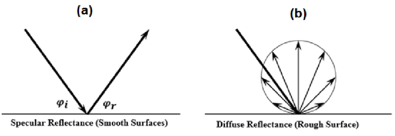
Solid surfaces are characterized by their hydrophilicity or hydrophobicity, which describes the degree to which a surface can be wet by water. A surface which is easily wet by water is referred to as hydrophilic while a surface which is not get wet by water is referred to as hydrophobic. These different wetting behaviors are related to the surface energies of the water and the solid material. Other factors that may influence the wetting behavior can be the parameters of the surface structure such as porosity, roughness, chemical heterogeneity or reactivity [9].
This chapter presents the theoretical background behind the thermodynamics of surface, and the parameters influencing the wetting properties of surfaces, which are needed to understand the results obtained in this thesis. The effect of the surface free energies as well as the surface structure on the wetting behavior of surfaces are discussed in this chapter.
1. Super-Hydrophobic Self-Cleaning Effect in Nature
The word “hydrophobicity” originates from the Greek word “hydro = water” and “phobos = fear”. According to the International Union of Pure and Applied Chemistry (IUPAC), the word hydrophobicity means “the association of non-polar groups or molecules in an aqueous environment which arises from the tendency of water to exclude non-polar molecules”. Hydrophobic surfaces, or water-fearing surfaces try to minimize the contact with the surface of the material. In contract to hydrophobicity, the word “hydrophilicity” (from Greek word “hydro = water” and “philia = love”) means that the water tries to maximize the contact with the materials and spreads on the surface. Hydrophilic molecules are known as polar molecules whereas hydrophobic molecules are known as non-polar molecules. As illustrated in Figure 2.1, A hydrophobic surface is one in which the water contact angle exceeds 90° whereas a hydrophilic surface is a surface in which the water contact angle is lower than 90°.
22 Figure 2.1. Static Water Contact Angle for (a) hydrophobic surface (b) hydrophilic surface
The term super-hydrophobicity was first introduced in 1996 by Onda et al. [10, 11] to describe water-repellent surfaces, in which the interactions between the material’s surface with the bulk water are weak [12]. The concept of super-hydrophobicity can be observed in nature [13] and is inspired from the lotus-leaves (also called the Nelumbo Nucifera Gaertn), which have a very high water repellency, from which the word super-hydrophobicity can be also referred to as the
lotus effect. On the other hand, the superhydrophilicity concept, or super-wetting was introduced
for the first time in 2000 in four articles by Japanese research groups [14-17] and describes strong interaction between the material surface and the bulk water.
Superhydrophilicity is observed with water contact angles lower than 5°. On the other hand, super-hydrophobicity is observed with water contact angles exceeding 150°, with very low contact angle hysteresis (not exceeding 10°) and low sliding angle (not exceeding 10°). The sliding angle or the tilting angle is the minimum angle of inclined solid at which the water slides off the surface whereas the contact angle hysteresis (CAH) is an index of the sickness of water on the surface of the material, and is defined as the difference between the advancing ( )
and the receding ( ) contact angles as illustrated in Figure 2.2. If additional liquid is added
to the sessile drop, the contact line advances in contract with removing liquid from the sessile drop, which results in reducing the contact angle to a receding value.
23 Figure 2.2. (a) Advancing and receding contact angles obtained with tilt angle (b) Advancing angle by adding
more liquid to the sessile drop (c) Receding angle by removing liquid from the sessile drop Reprinted from [18]
The contact angle hysteresis is very important when evaluating super-hydrophobicity, in fact, surfaces exhibiting high advancing contact angles and low receding contact angles may show poor hydrophobicity as the water drop will be trapped in the surface.
(2.1)
Figure 2.3. Hierarchical structure in plants (a) The lotus leaf Reprinted from [19] and (b) The Salvinia oblongifolia leaf Reprinted from [20]
The Lotus plant is characterized by its high repellency of water (contact angle of 164 ° and contact angle hysteresis of 3°). The super-hydrophobic effect of the Lotus plant is explained by the fact that its leaves have a combination of a Micro-structure and a structure (the Nano-structure is on top of the MicroNano-structure). As illustrated in Figure 2.3 (a), the lotus leaf exhibit hierarchical structures composed of convex structures with superimposed nanostructure (wax crystals). The waxes nano-structures are in the form of tubules for the lotus leaf (Fig 3. (a-iii)).
24
Figure 2.3 (b) shows the hierarchical structure of the Salvinia oblongifolia leaf, with multicellular hairs superimposed with nanostructures in the form of rod-like wax crystals (Fig 2.3. (b-(ii) and (iii)). Creating double-structure rough surfaces is a key factor in reducing the ability of adherence of dirt particles to the lotus leaf and other plants. The surface roughness increases the hydrophobic behavior of surfaces. A water contact angle of 164° has been reported for the lotus leaf [20] and a water contact angle of 162.3° has been reported for the Salvinia oblongifolia leaf [21].
The super-hydrophobic effect can also be observed with insects walking on water, such as water striders (Gerris remigis) or fisher spiders (Fig. 2.4 (a)). This behavior is explained by the fact that the surface tension of the water allows insects to walk on top of the water without sinking, even though they are denser than water. It is also due to the super-hydrophobic nature of their legs due to their hierarchical roughness structure [22]. A super-hydrophobic behavior was observed on water skater leg, with a measured water contact angle of 167.6° [23], which is due to the particular structure of water skater’s legs, micro-sized hairs, named microtrichia, or microsetae (Fig 2.4. (b)) which are covered by Nano-grooves (Fig. 2.4 (c)).
25 Figure 2.4. (a) Water strider floating on water [24] (b) SEM image water strider’s leg showing the micro-sized hair
(micro-setae) (c) SEM magnification showing the superimposed nano-grooves [23]
The surface tension, denoted ( ) is defined as the force exerted parallel to the surface, divided by the length of the length over which it acts.
(2.2)
The SI unit of surface tension is (N/m) or (Joule/m2). The surface tension notation is used for liquid, whereas for solids, the used notation is surface free energy. Water is considered as having one of the highest surface tensions, with 72.8 mN/m at 20°C, only exceeded by mercury, with a surface tension of about 480 mN/m at 20°C.
26 Figure 2.5. Attractive forces that the water molecules apply on each other (a) in the bulk liquid (b) at the surface of
the liquid
As illustrated in Fig. 2.5 (a), a water molecule in a bulk liquid is surrounded from all sides by other water molecules, which leads to equal attraction forces in all directions, resulting in a zero net force. On the other hand, Fig. 2.5 (b) shows that molecules at the surface of the liquid, with no surrounding molecules at the vapor interface, experience a net force that is directed towards the liquid, resulting in a surface tension.
There exist two types of forces with a solid-liquid interaction, the cohesive forces, which are the forces of attraction between water molecules, and the adhesion forces, which are the forces of attraction between water and a solid surface (water strider’s legs). Wetting behavior occurs when the adhesive forces are stronger than the cohesive forces, whereas a non-wetting behavior occurs when the cohesive forces are stronger than the adhesive forces.
Water striders use the principle of surface tension to stay at the surface of the water without sinking. In fact, the forces of attraction between the water molecules, or the cohesive forces between the water molecules are higher than the adhesive forces. The weight of the water strider is not enough to penetrate the surface of the water, and therefore, allows water striders to walk on the water without sinking.
In order to measure the surface hydrophobicity, the water contact angle (WCA) technique is followed [25]. The higher the water contact angle, the more surface hydrophobicity. The water contact angle value can also be used in order to calculate the surface free energies of solids. In principle, the lower the surface free energy of a solid surface ( ), the higher the water contact angle [26].
27
It has been proven that super-hydrophobicity can be achieved by combining two main parameters: a double roughness structure (dual micro and Nano structures) along with with a low surface energy [27].
2. Surface Energy
Knowledge of the surface free energies between two materials is of key importance in order to evaluate the degree of interaction between them. The contact angle methods [28, 30] has been used to characterize the wetting properties of surfaces and to determine the surface free energy of solids, and the interfacial surface free energies of two interacting materials.
2.1. DLVO Theory
The classical DLVO theory was developed in the 1940s by the Russian scientists Boris Derjaguin, Lev Landau, Evert Verwey and Theodoor Overbeek [30, 31]. It describes the adhesion between two interacting surfaces by the balance between two forces: the electrical double layer electrostatic repulsion force and the Lifshitz van der Waals attraction force.
The classical DLVO theory expresses the total interaction free energy ( ) as follows:
(2.3) The van der Waals attraction force is explained in details in the next section of this chapter. As for the electrostatic repulsion force for two interacting spheres with radius ( ), it is expressed by the Gouy-Chapman model (1910 and 1913) as follows [32, 33]:
(2.4) Where: ( ) (2.5) √ (2.6) Where:
28
The Boltzmann constant
The absolute temperature in Kelvin
The intermolecular distance (Distance of Separation) The valency of ions
The elementary charge Relative permittivity Permittivity of free space Surface potential
The reciprocal of the Debye length (The Debye length is the thickness of the diffuse double layer)
However, when using water as a medium, it is very important to account for the polar interaction energies that occur in water. Using the classical DLVO theory does not consider the polar interactions, and therefore it is important to use the extended DLVO Theory [34] which considers the polar interactions or the Lewis acid-base interactions. The total interaction free energy ( ) is then expressed by the extended DLVO theory as follows:
(2.7)
Fowkes [35] proposed that the work of adhesion ( ) between two interacting surfaces (a liquid on a solid surface) is given by:
(2.8)
Where ( ) represents the non-polar component (dispersion interactions), and ( ) represents the non-dispersion interactions’ component. The non-dispersion interactions include ionic bonding (Coulombic interactions) as well as hydrogen bonding interactions. Laskowski and Kitchener (1969) [36] have used the concept of the work of adhesion to show that all solids would have hydrophobic properties if the non-dispersion interactions’ component is null ( ), which occurs when the solid’s surface is free from any ionic or polar groups with which the water molecules can bond with.
29
According to the approaches of Fowkes [35] and van Oss-Chaudhury-Good [37-40], the surface free energy is given by the following formula:
(2.9)
Where ( ) and ( ) refer to the apolar and polar (acid-base) components of surface free-energy, respectively. The apolar interactions ( ) are represented as the Lifshitz-van der Waals (LW) interactions. On the other hand, the polar interactions are be represented as intermolecular acid-base interactions between Lewis acids (electron acceptor) and bases (electron donor) on the surface.
2.2. Apolar Interactions (The Lifshitz-van der Waals (LW))
The apolar interactions ( ) can be represented by the Lifshitz-van der Waals (LW) interactions which include the following interactions:
The instantaneous induced dipole-induced dipole interaction, or the dispersion interactions between two induced dipoles, as described by London [41]. This type of interaction occurs from the asymmetry of the electrons’ cloud in an atom, which makes one side of the atom more negatively charged and creates a momentary dipole. This momentary dipole induces other dipoles in the atom or molecule.
A permanent dipole in an atom is caused by the difference in electronegativity. The second type of Lifshitz van der Waals interactions consist of the induction interactions between one permanent dipole and one induced dipole, as described by Debye [42, 43]. A permanent dipole in an atom creates an electric field, which causes an orientation of
other permanent dipoles in the atom. These orientation permanent dipole-permanent dipole interactions are described as the Keesom interactions [44-57].
The London interaction is a universal and is always present in atom-atom interactions, whereas the Keesom and Debye interactions are not found in all materials since they require permanent dipole moments.
The common thing about these three interactions is the fact that their interaction energies decay with the 6th power of the intermolecular distance. The Keesom, Debye and London interaction free energies (in Joules) are given by the following equations (in vacuum):
30 (2.10) (2.11) (2.12) Where:
The dipole moment
The dielectric permittivity of free space The Boltzmann constant
The absolute temperature The intermolecular distance The polarizability
The ionization frequency
2.2.1. The Hamaker’s Approach for Dispersion Interaction
The dispersion interaction between two identical atoms or molecules (i) in vacuum is expressed as follows [40]:
(2.13)
Where:
The Hamaker constant
The number of atoms per unit volume And is calculated using the following equation:
(2.14)
From Eq. (2.12), the London interaction free energy equation can be re-written as follows:
31
Considering two different interacting materials (i) and (j), the dispersion interaction constant
can be calculated using Berthelot’s principle [48] as the geometric mean of the interaction
constants of the different materials:
√ (2.16)
The Hamaker constant for two different interacting atoms is then given by Eq. (2.17), which is referred to as the Hamaker combining rule:
√ (2.17)
In 1936, Hamaker [49] was the first to calculate the dispersion interaction energy, or the van der-Waals-London interaction energy:
(2.18)
The Hamaker constant can be substituted by ( ) when it comes to the interaction between two atoms of the same solid material (1) in medium (3) [40]:
√ √ (2.19)
(2.20)
Where ( ) refers to the Hamaker constant of the solid and ( ) refers to the Hamaker constant
of the medium.
Likewise, and when it comes to the interaction between two atoms of different materials (1) and
(2) in medium (3), the Hamaker constant can be substituted by ( ):
(2.21)
(√ √ )(√ √ ) (2.22)
From Eq. (2.19), ( ) is always positive (or equal to zero). Hence, two identical molecules of
the same material (1) in medium (3) always attract each other, although ( ) can equal zero if the Hamaker constants of the solid ( ) and the medium ( ) are equal to each other. On the
32
other hand, for two different materials (1) and (2) in medium (3), the Hamaker constant ( )
from Eq. (2.22) can be negative when:
And when:
Under the conditions where the Hamaker constant ( ) is negative, the dispersion interaction
energy becomes repulsive ( ) [50-51].
Padday and Uffindell [52] demonstrated that the Hamaker approach can be applied for the n-alkanes by comparing the experimental values of the surface tension ( ) of various n-alkanes to the calculated values using the following formula:
(2.23)
Where ( ) is the cohesion work resulting from the London dispersion forces, ( ) is the surface tension and ( ) is the intermolecular distance. The calculated values of the surface tension of n-alkanes were in good agreement with the experimental measured values, which proves that n-alkanes are of dispersion type.
However, Horn [53] showed that the Hamaker approach is not accurate due to the many-body effects. In fact, the field that an atomic dipole creates is affected by the neighboring atoms. Yildirim [54] also showed that the Hamaker approach cannot be used for some colloidal systems since it has a common point with the classical DLVO theory, which consists in ignoring the existence of hydrophobic interactions between particles of hydrophobic materials.
2.2.2. The Lifshitz Approach for Dispersion Interaction
In 1955, Lifshitz deduced the same equation (Eq. (2.23)) using a different calculation technique [55]. Lifshitz followed a purely macroscopic approximation, his starting point was Maxwell equations, where the magnetic and electric fields are under temporary and quick fluctuations. The dispersion force can be calculated by the Lifshitz approach by macroscopic properties such as the dielectric constants and refractive indexes of interacting bodies. The derivation of the
33
Lifshitz theory is not included in this chapter, and the full theory is complicated and can be found in references by Mahanty and Ninham [56] Hough and white [57] and Israelachvili [58].
The Hamaker constants of two interacting atoms of different materials (1) and (2) in medium (3) can be calculated from the Lifshitz theory as follows [59]:
( ) ( ) √ { } (2.24) And: ( ) √ (2.25) Where:
Dielectric constant for medium (1) Dielectric constant for medium (2) Dielectric constant for medium (3) Refractive index for medium (1) Refractive index for medium (2) Refractive index for medium (3)
Absorption frequency in the UV region ( )
The first term of the equation represents the zero-frequency energy of the van der Waals energy, which corresponds to the Keesom and Debye interaction energies, while the last term in the equation corresponds to the dispersion energy, which corresponds to the London interaction energy. The Hamaker constant, and therefore the van de Waals forces can be calculated accurately using the Lifshitz theory given that the optical data for the materials of interest are known.
By calculating the Hamaker constant for different liquids, Israelachvili [60] was able to calculate the surface tension of these liquids. The apolar component of the surface tension ( ) is related to the Hamaker constant by the following equation used by Israelachvili:
34
(2.26)
Eq. (2.26) is the same as Eq. (2.23), only the approach used to calculate the Hamaker constant is different (Eq. (2.26) uses the Lifshitz approach while Eq. (2.23) uses the Hamaker approach). The Lifshitz van der Waals interaction energies and interaction attracting forces is presented in Table 2.1 for different geometries.
Table 2.1. The Lifshitz van der Waals interaction energy and interaction force for different geometries [40, 59]
Geometry The Lifshitz van der Waals interaction energy
The Lifshitz van der Waals interaction Force
Two interacting flat surfaces
Flat surface interacting with a
spherical particle with radius ( ) Two interaction spheres with
radius ( )
2.2.3. Interfacial Lifshitz van der Waals Interactions
The surface tensions ( ) of a liquid is defined as the surface free energy per unit area. In vacuum, the surface tension of a liquid is related to the free energy of cohesion ( ) by the
following equation [61]:
(2.27)
The previous equation applies also for solids, with the exception that ( ) for solids is not their free energy of cohesion, but rather their free energy for interacting with liquids [62].
According to the Lifshitz approach, Chaudhury [63] had experimentally demonstrated that the London (dispersion), Debye (induction) and Keesom (dipole) interactions’ contribution to the apolar component of the surface tension (the Lifshitz van der Waals) ( ) are additive:
35
On a macroscopic level, the three types of van der Waals interactions can be treated together as the total of apolar (Lifshitz van der Waals) interactions [40].
Calculating the interfacial tension ( ) between two different materials (1) and (2) is of main
interest in surface science and colloids as it helps quantifying the free energy of inter-particle or inter-molecular interactions in condensed systems [64]. While the interfacial tensions between two liquids can be measured [65], the interfacial tensions between a liquid and a solid are not directly determined [64]. Therefore, in order to calculate the interfacial tensions between a liquid and a solid ( ), one needs to use the surface tensions ( ) and ( ) of the two interacting materials.
Good and Girifalco [64] and Fowkes [66] have demonstrated that if only the dispersion interactions are available, the interfacial tension between a liquid and a solid ( ) is expressed as follows:
(√ √ ) (2.29)
Or:
√ (2.30)
This equation is referred to as the Good-Girifalco-Fowkes combining rule [34]. This equation has been proved to be experimentally accurate within 2% [67].
From equation (Eq. (2.27)), the surface tension ( ) of a liquid is equal to half the free energy of cohesion ( ), with opposite sign. The apolar component of the free energy of cohesion of
material (1) is then given by:
(2.31)
The free energy of interaction between material (1) and material (2) (in vacuum) is related to the surface tensions of the interacting materials by the Dupré equation [68] expressed as follows:
(2.32)
36
√ (2.33)
This is a very important equation, since the Lifshitz van der Waals interactions are universal and always occurring at surfaces, and since the free energy of interaction is negative, which means that the interaction between two polar materials is always attractive.
Likewise, the interaction between two particles of materials (1) immersed in liquid (2) is given as follows:
(2.34)
And the interaction between two particles of different materials (1) and (2) immersed in liquid
(3) is given as follows:
(2.35) Substituting:
√ √ √ (2.36)
From Eq. (2.33), ( ) can be expressed as follows:
(2.37) This is a confirmation of the Hamaker combining rule (Eq. (2.17)).
2.3. Polar Interactions (The Lewis Acid-Base)
Chaudhury [63] has shown that the three apolar interactions (London, Debye and Keesom) are additive and form the Lifshitz van der Waals interactions (LW). On the other hand, the polar (Lewis) nature of surfaces was examined as a completely different phenomenon from the LW apolar interactions.
In aqueous media, and especially for solids which are rich in oxygen, the principal polar interaction is hydrogen bonding, which involves donors and acceptors [40]. Polar surface interactions are not limited to hydrogen bonding, but can be extended to phenomena dealing with electron donating/accepting as emphasized by Lewis [34].
37
Since the apolar (Lifshitz-van der Waals) and polar (acid-base) components of the surface tension are additive (Eq. (2.9)) [34], it follows that:
(2.38)
Where ( ) is the change in free energy due to Lifshitz-van der Waals interactions, and
( ) is the change in free energy due to acid-base interactions (Lewis interactions).
From Eq. (2.27), the surface tension of a liquid ( ) is related to the free energy of cohesion ( ) by the following formula:
(2.39)
For the acid-base interactions, the interaction free energy between two materials (i) and (j) is given as follows [69]:
√ √ (2.40)
Where ( ) is the electron donor, or the basic component, whereas ( ) is the electron acceptor, or the acidic component. There are two types of interactions in this equation:
An electron donor of material (i) interacting with an electron acceptor of material (j) An electron donor of material (j) interacting with an electron acceptor of material (i) By thermodynamic convention, a negative sign of ( ) means an attraction. It is given that ( ) is always attractive or zero, given the square roots in the write hand-side of the equation are positive or equal to zero [40].
The polar acid-base free energy of cohesion of a material (i) is then given by [40]:
√ (2.41)
Since ( ), then the polar component of the surface tension of material (i) is given by:
√ (2.42)
38
(2.43)
From Eq. (2.43), the acid-base interfacial tension between two materials (1) and (2) can then be expressed as:
(2.44)
Substituting Eq. (2.40) and Eq. (2.42) in Eq. (2.44), the acid-base interfacial tension between two materials (1) and (2) can be calculated as follows:
(√ √ √ √ ) (2.45)
Simplifying:
(√ √ ) (√ √ ) (2.46)
3. Van-Oss-Chaudhury-Good Approach for the Estimation of Surface Free
Energy of Solids (Acid-Base Theory)
According to the approach of Van-Oss-Chaudhury-Good (OCG), the surface free energy change upon two interacting surfaces (solid-liquid) is given by:
√ √ √ (2.47)
The changes in free energies associated with the solid-liquid interaction is given by the following equation:
(2.48)
Therefore, and using both equations, the interfacial surface tension of two interacting surfaces (solid-liquid) can be calculated using the following formula:
39
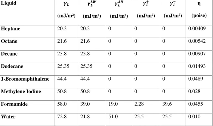
The four unknown in the previous equation are the surface free energy components of the solid ( ). The liquid surface free energy components are available in the literature and are presented in Table 2.2
Table 2.2. Values of the surface tension components and viscosities of different liquids used in micro-calorimetric and contact angle measurements
Liquid (mJ/m²) (mJ/m²) (mJ/m²) (mJ/m²) (mJ/m²) η (poise) Heptane 20.3 20.3 0 0 0 0.00409 Octane 21.6 21.6 0 0 0 0.00542 Decane 23.8 23.8 0 0 0 0.00907 Dodecane 25.35 25.35 0 0 0 0.01493 1-Bromonaphthalene 44.4 44.4 0 0 0 0.0489 Methylene Iodine 50.8 50.8 0 0 0 0.028 Formamide 58.0 39.0 19.0 2.28 39.6 0.0455 Water 72.8 21.8 51.0 25.5 25.5 0.010 The Van-Oss-Chaudhury-Good (OCG) in order to calculate the surface free energy components of solids ( ).
Gibbs free energy of interaction, or the work of adhesion is related to the interfacial energies through Young’s equation [62]:
(2.50)
Where ( ) is the surface tension of water and ( ) is the interfacial tension between the solid and liquid.
Combining Eq. (2.48) and Eq. (2.50) we get:
40
(√ √ √ ) (2.52)
From this equation, the free energy components of solids ( ) can be determined by determining the contact angles for three different liquids of know properties (Table I) on the surface of the solid of interest. Three equations with three unknown can be solved to obtain the values for .
In the case an apolar liquid is deposited on the surface of a talk sample and the Young contact angle is measured, the apolar Lifshitz van der Waals interactions dominate and Eq. (2.52) can be reduced to the following:
√ (2.53)
Since both ( ) and ( ) are equal to zero, can be determined from a single contact angle measurement, provided that the values of ( ) and ( ) of the apolar liquid are known (
) and ( ). Once the value of is calculated, it can be used to determine the
values of ( )) and ( ).
Once the three surface tensions are known ( ), the surface tension of a solid ( ) can be determined from the following equation:
√ (2.54)
4. Surface Structure
4.1. Wetting Behavior on Smooth Surfaces 4.1.1. Young’s Model:
The surface wettability of a chemically homogeneous smooth surface depends on the chemical surface composition.
Theoretically, the contact angle ( ) of a droplet deposited on a perfectly flat surface can be calculated using Young’s equation [70]:
![Table 2.1. The Lifshitz van der Waals interaction energy and interaction force for different geometries [40, 59]](https://thumb-eu.123doks.com/thumbv2/123doknet/2186766.10952/34.918.101.825.323.567/table-lifshitz-waals-interaction-energy-interaction-different-geometries.webp)
![Figure 2.6. Young, Wenzel and Cassie models [72]](https://thumb-eu.123doks.com/thumbv2/123doknet/2186766.10952/42.918.118.664.668.875/figure-young-wenzel-cassie-models.webp)
![Table 4.2. Structural properties of stable Alumina ( ) and Metastable Aluminas [103-105]](https://thumb-eu.123doks.com/thumbv2/123doknet/2186766.10952/79.918.102.813.110.431/table-structural-properties-stable-alumina-metastable-aluminas.webp)
![Table 4.3. Transformations of metastable alumina polymorphs [103, 106]](https://thumb-eu.123doks.com/thumbv2/123doknet/2186766.10952/80.918.101.800.713.935/table-transformations-of-metastable-alumina-polymorphs.webp)
![Figure 4.3. Reversible variation of the WCA by cyclic use of UV exposure and ultrasonic treatment Reprinted from [39]](https://thumb-eu.123doks.com/thumbv2/123doknet/2186766.10952/93.918.320.601.667.893/figure-reversible-variation-cyclic-exposure-ultrasonic-treatment-reprinted.webp)