HAL Id: hal-00472321
https://hal.archives-ouvertes.fr/hal-00472321
Submitted on 12 May 2010
HAL is a multi-disciplinary open access
archive for the deposit and dissemination of
sci-entific research documents, whether they are
pub-lished or not. The documents may come from
teaching and research institutions in France or
abroad, or from public or private research centers.
L’archive ouverte pluridisciplinaire HAL, est
destinée au dépôt et à la diffusion de documents
scientifiques de niveau recherche, publiés ou non,
émanant des établissements d’enseignement et de
recherche français ou étrangers, des laboratoires
publics ou privés.
Towards an Approach for Building Reliable
Architectures
Abdelkrim Amirat, Mourad Oussalah, Tahar Khammaci
To cite this version:
Abdelkrim Amirat, Mourad Oussalah, Tahar Khammaci. Towards an Approach for Building Reliable
Architectures. IEEE International Conference on Information Reuse and Integration (IEEE IRI’07),
Aug 2007, United States. pp.467-472. �hal-00472321�
Towards an Approach for Building Reliable Architectures
Abdelkrim Amirat, Mourad Oussalah, and Tahar Khammaci
Laboratoire LINA CNRS FRE 2729, Université de Nantes
2, Rue de la Houssinière, BP 92208,
44322 Nantes Cedex 03, France
{Abdelkrim.Amirat, Mourad.Oussalah, Tahar.Khammaci} @Univ-Nantes.fr
Abstract
Composing an application out of independent, reusable pieces has been a key challenge since the early days of software engineering. In this paper we examine some aspects of software architecture. We introduce our COSA+ model built in order to provide some enhancement in the COSA1 one. Our main contributions are the new structure given to an explicit connector, and the conceptual view of the different abstract levels used to define the applications architectures. Profits expected from these improvements are numerous; mainly we can quote the reduction of the production costs and the time to market, simplify the maintenance operations, and foresee supports for the evolution of the software architecture.
1. Introduction
In spite of the remarkable development of platforms dedicated to CBSD and Architecture Description Languages (ADLs), a certain drawbacks still exist and deserve to be investigated and studied. Among these we can quote:
• The description of the attachments and bindings among architectural elements (components, connectors, and configurations) is a manual task. • The developer of an application can connect nay arbitrary components by any kind of connectors without any semantic check of the resulting links. Thus, the checking of the validity and the correction of the developed architectures are also manual task and left to the knowledge of the developer.
• The definition and the instantiation of the architectural elements are always done at the same level; therefore the reusability is reduced.
To overcome these drawbacks, we propose an approach which aims to develop the software architectures where the components and connectors are of first-class entities and have the same importance. So connectors are special-purpose components that isolate component interfaces and encapsulate all the rules which govern the interactions among components. These free components to focus only on their functional core business such as computations and data storages and so on. In addition to and contrary of the classic component based models, in our model we consider
that: (1)- Bindings are special-purpose connectors conceived to connect components and their underlying component containers (configurations). (2)- Attachments are encapsulated inside connectors to relieve the application builder of the effort needed to define the attachments, the bindings and the cheeking task of the coherence of the connected elements. (3)- The concept of architecture is defined by “logical architecture”, developed by the application builder, and its memory image “physical architecture” built automatically. Thus, components and connectors are assembled in an easy and coherent way in the form of an architectural puzzle without any effort to describe links among components and connectors or between components and configuration. Consequently, this approach accelerates the development of components, improves testability, coherence, maintainability and promotes component markets [1].
The rest of this paper is organized as follows: section 2 presents the various levels of abstraction of logical and physical architectures. Section 3 defines the different elements and the necessary basic concepts in both types of architectures. Section 4 sketches the application of our approach to the client server example; also it gives a comparative study with the ADL Acme. Our conclusion as well as our future works is presented in section 5.
2.
Logical and physical architecture
The architecture form that we have is a flat logical image which allows us to see how components and connectors are assembled. This image represents the logical architecture of the application which is not enough to give a direct answer to some important questions such as:• Which components connected with a given component?
• Who many components are defined inside a given composite component (configuration)? • Which connectors are connected to a given
component?
1
COSA (Component Object based Software Architecture) is Meta model for the structural description of software architectures developed by MODAL research group at LINA Laboratory, University of Nantes, France [6].
These questions must be answered in order to update and evolve the software architectures. Actually, to determine such type of information we have to write routines that need to go through all the elements of the architecture and calculate the needed information. This led us to define another physical architectural image which represents the image of the logical architecture in memory in a form of a directed graph. This image will serve as a support for the logical architecture. So, we can find the answer of the previous questions in a direct way and without any effort sequential access to the logical architecture.
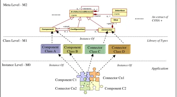
2.1 Logical architecture
In our approach we identify three categories of stakeholders: Framework Builder, Software Architect and Application Builder. Each stakeholder acts at a different level of abstraction. In the following paragraph, we present three levels of abstraction associated with the objectives of each category of stakeholders, as indicated in figure 1. 2.1.1 Meta level (M2). At this level we can find the framework builder which describes the fundamental concepts used to be instantiated to create the basic architectural elements. So the elements of the M2 level represent types for the elements of the architecture level. This typing mechanism is
expressed by the relation “Instance Of”. Thus, each element of the model is typed by its meta element. 2.1.2 Architecture level (M1). This level of abstraction represents the elements defined by of software architect.
• The elements of this level are a types of components and connectors defined by the meta model COSA+.
• New types of components and connectors can be defined from the elements which already exist at this level using the inheritance mechanism. At this level, the architect defines and organises these architectural elements in the form of libraries of types of components and connectors like the commercial-off-the-shelf (COTS, [2]) in order to facilitate their deployment in different configurations. Let us note that the principle of reuse has to be widely exploited to define these libraries and the deployment of connectors must be preserved by using declared interfaces which mask the management mechanism of the connections.
2.1.3 Applications level (M0). At this level, we suppose that the application builder has libraries of types of components and connectors on the shelf at M1 level. At first, he/she creates the instances of architectural elements which he/she needs, and then, he/she installs each connectors instance among the corresponding components instance available at this application. So, the application is built in an incremental way in a form of a Lego Blocks.
Figure 1. Levels of abstraction in the logical architecture
2.2 Physical architecture
The physical architecture will serve as a support to the logical architecture by automatically building the image of the existing links between elements
deployed in architecture. The physical architecture is principally conceived using only two levels of abstractions which are the following (figure 2). 2.2.1 System level. At this level, we find a special type of elements called Connection Manager (CM)
Meta Level - M2 Class Level - M1 Connector Class C Connector Class D Component Class B Component Class A Instance Of
Instance Level - M0 Instance Of
Connector Cn1 Component C2 Component C1 Connector Cn2 Instance Of ArchitecturalElement +name Interface +name +elements 0..1 0.. * +owner 0..*
Component Configuration Connector 0.. * 0..* +detail 0..1 Glue +glue 0..1 An extract of COSA + …… …… Library of Types Application
which contains the necessary information used in the definition and theconstruction of the different nodes instances needed to build the graph representing the physical architecture.
2.2.2 Instance level. During the installation of connectors done by the application builder to construct his/her application, the system creates an instance of a connection manager for every component concerned by this installation if it does not already exist. Thus, the instance level of the physical architecture takes care of the management of all connections among elements of the logical architecture instantiated at the application level.
Figure 2. Abstraction Levels in the physical architecture
3.
Basic concepts of architectures
In this section, we present the various concepts and artefacts needed by our approach to construct both types of architecture. In a first time we introduce the main elements of the logical architecture with brief description for components and configurations and we give some details about connectors since they represent the principle axe of our approach. In a second time we introduce the basic elements of the physical architecture which are the connection manager and topological graph. 3.1 Components
Components represent the elements of the computation and the data storage of a software system. Each component has one or more interfaces; each interface has one or more ports. Ports are the connection points between components and their environment. Any interaction with a component provokes the invocation of a service. A component can require services from other components and will provide services to the other components. A component also has properties, constraints, and can have a several implementations. Components are instantiated from their types; these types can be parameterised with the aim of facilitating their reuse. It is functionally clear that components should be designed with a high cohesion and low coupling [1], [3], [4]. Each component has the following interface: Component_TypeName (required_Interf, provided_Interf); 3.2 Configurations
A configuration represents a graph of components and connectors and defines the way they are interconnected. The notion of a configuration is necessary to determine if components are connected correctly, i.e. their interfaces are compatible, then the corresponding connectors allow a correct communication, and the combination of their semantic gives an acceptable behaviour. Configurations in COSA are first class entities that can be instantiated several times and therefore give several architectures of a given software. A configuration can have zero or several interfaces defining ports and services for this configuration. Ports are indented to be connected with the ports of the internal components and/or ports of the external components or configurations. Each configuration has the following interface:
Configuration_TypeName (required_Interf, provided_Interf); 3.3 Connectors
a)- Definition: Our definition is mainly based on that given by Shaw and Garlan who say “Connectors mediate interactions among components; that is, they establish the rules that govern component interaction and specify any auxiliary mechanism required” [5]. In COSA [6], a connector is defined by an interface and glue, as shown in figure 3. Basically, the interface describes the necessary information of the connector, including a number of roles and the different types of services provided by the connector. The roles are the points of interaction of a connector with its environment. A role is the interface of a connector called to be connected with a port of a component or a configuration. Each role has a required or provides type of services. The glue describes the functionality of the connector and it can be a simple protocol connecting the roles or a complex protocol having several operations such as data format conversion, data transfer, adapting services etc. Connectors have also properties and constraints [6], [7], [8].
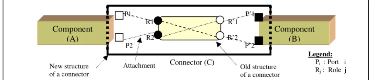
Figure 3. The structure COSA connector
Our contribution at this level consists in enhancing the structure of COSA connectors by encapsulating the attachment links (figure 4). So, the application builder will have to spend no effort in connecting connectors with its compatible components. Consequently, the task of the developer consists only in choosing a suitable type of connectors which is compatible with the types of components which are expected to be connected.
Connector_TypeName (List of component interfs) { Roles {List of roles}
Services {List of services} Properties {List of properties} Constraints {List of constraints} Glue {The communication protocol} }
Instance Level System Level CM1 Link CM2 Connection Manager Class Instance Of
Figure 4. The structure COSA+ connector.
In figure 5 we represent an example with two components (A and B) connected with a connector (C). In this figure we represent the design of a conventional connector defined in COSA or in other ADLs as indicated by the inner frame (Old structure of a connector) and the design of the new connector that we propose as indicated by the outer frame (New structure of a connector) in which we encapsulate
the attachment links among ports and roles, in our model we call these links connections.
b) - Description: According to our hypothesis concerning the pyramid of abstraction levels given in section 2, the software architect has two ways to describe a new connector at the architecture level. • Instantiate a new connector from the type exists in
the level meta level.
E.g. The instantiation of the connector of the M2 level gives an empty skeleton filled by the desired values to produce the expected type of connectors. In the following paragraph we give some details of the connector (C) described in figure 5.
Figure 5. The new structure of connector.
Connector C (A.P1, A.P2, B.P’1, B.P’2) { Roles = {R1, R2, R’1, R’2}
………….
Glue = {R1 = R’2, R2 = R’1}
Connection = { A.P1 = C.R1, A.P2 = C.R2,
B.P’1= C.R’1, B.P’2= C.R’2 } };
• Reuse a description existed in the level M1 and applies some modifications via the mechanism of the inheritance (specialization).
E.g. This example shows the specialization at the M1 level of the connector C defined in the previous example. So, C is extended by: a new interface X.P, two roles R3, R’3, a glue rule R3=R’3, and a connection rule. The resulting connector D can be used to connect the component X using the port P with the component A or B.
Connector D Extends C (A.P1, A.P2, B.P’1, B.P’2, X.P) { Roles = {R1, R2, R’1, R’2, R3, R’3}
……….
Glue = {R1 = R’2, R2 = R’1, R3 = R’3} Connection = { A.P1 = C.R1, A.P2 = C.R2,
B.P’1= C.R’1, B.P’2= C.R’2, X.P = C.R3 } }; c) - Installation: The application builder can instantiate a connector from its description (type) and then install it in the application. So, installing a connector means connecting explicitly two or more components using this connector. We use the following primitives to realize the installation operations of elements at the instance level.
Component (TypeName: ComponentName(interfaces)); Connector (TypeName: ConnectorName(interfaces)); Configuration (TypeName: ConfigurationName(interfaces));
Once the elements to be connected are instantiated the connector is installed between the components using the following syntax:
ConnectorName (Compos1.Interfi, Compos2.Interfj …);
In our approach we consider that the binding links as a special-purpose connectors and their installation is possible only between a configuration and its inner components or between connectors.
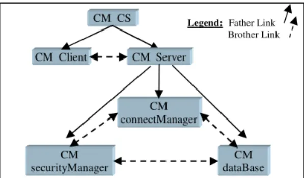
BinderName (Element1.Interfi, Element2.Interfj …); 3.4 Connection Manager (CM)
a)- Definition: this element is an entity of the physical architecture associated with exactly one component in M0 level of logical architecture. The function of each CM is to encapsulate the various connections of a component with its environment. During the installation of the connectors, a topological graph is built in back plan of the logical architecture. The nodes of the graph are the created CMs and the rows represent the connections between components associated with the previous CMs. Every CM has the following attributes (figure 6): • ComponentName: represents the name of the component associate with this CM.
• TheConnection: this attribute allows us to identify all connectors which are connected to the component associate with this CM.
• FatherConnection: is a link which allows the connection of a CM associated to an internal component (son) with the CM of the configuration (father) to which it belongs. This link is directed from the CM father to the CM son.
• BrotherConnection: is a link which allows the connection of two CMs of the same level of hierarchy. These two CMs are associated with two
Connector_TypeName (List of component interfs) { Roles {List of roles}
……
Glue {The Communication protocol} Connection {List of attachments} }
P1 P’1
R1 R’1
R2 R’2 P2 P’2 Component (A) Component (B) New structure of a connector Old structure of a connector Connector (C) Attachment Legend: Pi : Port i Rj : Role j
components which belong to the same hierarchical level and are directly connected (figure 7).
Figure 6. CM structure
b)- Instantiation : The CMs are to be instantiated at the M0 level of the physical architecture. So, every time we install a connector between two components in the logical architecture, we generate a CM at the physical architecture associated with each component connected by this connector if it does not exist.
c)- Installation: Installing a CM means to create an instance and putting it in the graph after filling the ComponentName and TheConnection attributes witch indicates respectively its associated component and the connector that activates its existence. d)- Propagation: This mechanism consists of calculating and updating a number of links in the graph after the installation operation of a CM. This mechanism completes the attributes Connection-Father and ConnectionBrother by establishing links between this CM and his father and brothers. 3.5 Topological graph. During the installation operations of the elements a topological graph is built automatically. The nodes of the topological graph are instances of the CM. These nodes are interconnected by rows that represent links of membership elements (father and brothers). The hierarchies in the graph represent also the levels of components. The root node in the graph represents the global configuration of the application. The applications builder has the possibility to display information concerning the topological graph without modifying it. We can deploy this graph in other applications.
4. Case study
Figure 7 shows the hierarchical configuration of a simple client-server academic application.
Figure 7. Hierarchical client-server configuration
4.1 Representation of client-server in COSA+
Figure 8 gives the different types used to be instantiated in this example. The representation in COSA+ of the Client-Server architecture is given by figure 9. In figure 10, we present the topological graph associated with this example of architecture.
Figure 8. Element types of Client-Server
Figure 9. Element instances of client-server
Due to space constraints of this paper we give only some details about Trpc connector type.
Connector Trpc (Tclient.sendRequest, Tserver.receiveRequest) { Roles = {caller, callee};
Glue = {caller = callee};
Connection = {caller = Tclient.sendRequest,
callee = Tserver.receiveRequest }; …..} 4.2 Comparison with the ADL Acme
Based on the study of the previous example, we present in this section a simple comparative study between proposed architecture model and the ADL Acme and in the same time we present the solutions for drawbacks introduced in the beginning of this paper. This study is based on the following criteria:
Component {Tclient : Client ;
TconnectManager : connectManager; TsecurityManager : securityManager; Tdatabase : dataBase }
Connector {TSQLQuery : SQLQuery;
TclearanceRequest : clearanceRequest; TsecurityQuery : securityQuery); Tbinding : Binder; Trpc : Rpc; } Configuration { Tserver : Server = { SQLQuery (connectManager(dbQueryInft) , dataBase(securityManagementIntf); clearanceRequest (connectManager(securityCheckIntf) , securityManeger(securityAutorization); securityQuery ( securityManager(credentialQuery) , dataBase(securityManagementIntf); Binder (Server (receiveRequest),
connectManager(externalSocket); } Tcs_Config : CS = { Rpc (Client(sendRequest), Server(receiveRequest)) } security- Manager connect- Manager data- Base Server Configuration security Query Clearance Request SQLQuery Client Rpc Binder CS Configuration ConnectorManager Type_Name {
ComponentName Associated component name; TheConnection {List associated connectors}; FatherConnection {Father CM name};
BrotherConnection {List of CM brothers name} } Components Tclient ( sendRequest ) {…}
TconnectManager ( externalSocket, securityCheckIntf, dbQueryInft ) {…}
TsecurityManager(securityAutorization, credentialQuery) {..} Tdatabase ( securityManagementIntf, QueryIntf ) {…}
Connectors TSQLQuery ( TconnectM.dbQueryIntf, Tdatabase.QueryIntf ) {…} TclearanceR ( TconnectionManager.securityCheckintf, TsecurityManager.securityAuthorization ) {…} TsecurityQ (TsecurityManager.credentialQuery, Tdatabase.securityManagementIntf ) {…} Tbinding ( TconnectioManager.externalSocket, Tserver.ReceiveRequest ) {…} Trpc ( Tclient.sendRequest, Tserver.receiveRequest ) {…} Configurations Tserver (receiveRequest) {
IncludeComponent TconnectM, TsecurityM, Tdatabase; IncludeConnector TSQLQuery, TclearanceR,
TsecurityQ, Tbinding } Tcs_config () {
IncludeCompnent Tclient, Tserver_Config; IncludeConnector Trpc }
Figure 10. Physical architecture of Client-Server
4.2.1. Legibility. If we examine architectures written in Acme we find that the definitions of the types and their instantiation are merged in the same architectural level. In our approach we have made a very clear separation between the description phase and the instantiation one by putting them in two different architectural levels. So, we can note that the developed architectures using COSA+ are more legible than those developed with Acme.
4.2.2. Evolution. Via the topological graph we can easily replace or add a component in the architecture since we have all the connections information registered in the connection manager node associated to the previous component. We can realise these operations without any manual effort on behalf of the application builder because there is no need, to write the attachment and binding links among elements. On the other hand in Acme attachments and bindings are being updated all the time manually. Consequently we can say that the evolution process is easier in COSA+ than that in the ADL Acme. 4.2.3. Reusability. By firstly defining the types of the architectural elements in COSA+ and then instantiate these elements in a second phase separately alone or inside their underling component container (configuration) via the included primitive. In Acme each element can be instantiated only in the context of his definition and not outside. So we can say that COSA+ model allows better reusability of the architectural elements than in the ADL Acme. 4.2.4. Reliability. In COSA+, attachment links are encapsulated in the connectors and Bindings are treated as special-purpose connectors. Thus, all elements being installed in the application are well semantically and correctly connected since connectors are only installed among compatible component interfaces. This style of automatic cheeking is not allowed by Acme because the application builder has no mean to check the links described manually. Consequently, architectures were written in COSA+ are all the time coherent.
5. Conclusion and future works
The approach that we have proposed describes a model of architecture based on three fundamental concepts. The first one is the new structure of a connector in which we encapsulate the attachments. Such connectors are first-class entities and have equal importance like components. We consider them as reusable COTS elements; the second concept is the special-purpose connector who performs the role of the bindings deployed to connect components with their configurations; the third concept is the CM which represents the nodes of the topological graph associated with a given logical architecture. The graph is automatically generated according to the installation operations of connectors in the application. This graph allows a good traceability of the hierarchical links between the components of the same level and between the components with their configuration. This traceability is necessary to realize the updating operations and thus facilitate the evolution process of architectures. Note that we can save the topological graph associated with a given configuration in order reuse it with some modifications or to deploy it as it is in other applications. It seems to us that our approach is a supplementary step towards the development of large-scale software applications by assembly components already initiated by the paradigm CBSD. Our future works concern with the impact of this approach on the maintenance activity and the evolution process of the software architectures.
6. References
[1] Crnkovic, I., and Larsson M., Building Reliable
Component-Based Systems, Artech House, July 2002. [2] Anderson, T., Feng, M., Riddle, S., and Romanovsky,
A. “Protective Wrapper Development: A Case Study”. 2nd
Int. Conference on COTS-based Software Systems (ICCBSS’03). Ottawa, Canada. Feb., 2003. LNCS Volume 2580 pp. 1-14 Springer-Verlag 2003.
[3] Garlan, D., Monroe, R.T., and Wile, D. “Acme: Architectural Description Component-Based Systems, Foundations of Component-Based Systems”. Cambridge University Press, 2000, pp. 47-68.
[4] Garlan, D. “Software Architecture and Object-Oriented Systems”. IPSJ Object-Orieted Symposium, August 2000, Tokyo, Japan.
[5] Shaw, M., and Garlan, D. Software Architecture:
Perspectives on an Emerging Discipline. Prentice-Hall, Upper Saddle River, N.J., ISBN 0131829572, 1996. [6] Adel Smeda, Mourad Oussalah, and Tahar Khammaci, A Multi-Paradigm Approach to Describe Complex Software System, WSEAS Transaction on Computers, Volume 3, No.4, October 2004, pp.936-941. [7] Medvidovic, N. and Taylor, R.N. “A Classification and Comparison Framework for Software Architecture Description Language”. IEEE Transactions on Software Engineering Vol. 26, No1, January 2000.
[8] Mehta N.R., Medvidovic N., and Phadke S., “Towards
a Taxonomy of Software Connectors”, ICSE’00, Ireland
CM Client CM CS CM Server CM connectManager CM dataBase CM securityManager
Legend: Father Link Brother Link