Heat SET 2007 Heat Transfer in Components and Systems for Sustainable Energy Technologies 18-20 April 2007, Chambery, France
DEVELOPMENT AND EXPERIMENTAL VALIDATION OF AN ORGANIC RANKINE CYCLE MODEL
Vincent Lemort,vincent.lemort@ulg.ac.be
Cristian Cuevas,ccuevas@student.ulg.ac.be
Jean Lebrun,j.lebrun@ulg.ac.be
Ion Vladut Teodore,IonVladut.Teodorese@ulg.ac.be
Sylvain Quoilin,squoilin@student.ulg.ac.be
Thermodynamics Laboratory, University of Liège Campus du Sart-Tilman, B49, B-4000 Liège
Belgium
ABSTRACT
This paper presents both a numerical model of an Organic Rankine Cycle (ORC) and an experimental study carried out on a prototype of such a cycle working with refrigerant HCFC-123, and whose heat sources consist in two hot air flows. The ORC model is built by connecting different sub-models: the heat exchanger models, a volumetric pump model and a scroll expander model. Measured performances of the ORC prototype are presented and allow the validation of the ORC model. This model is finally used to investigate potential improvements of the prototype.
INTRODUCTION
Organic Rankine Cycles (ORC) are particularly suitable for recovering energy from low-grade heat sources, such as waste heat in an industry process, exhaust gas or cooling system of an internal combustion engine, exhaust gas from a turbine, or heat produced by solar concentrators.
Past studies have shown the influence of working fluid thermodynamic properties on the ORC performances (Hung, 2001; Liu et al., 2004; Maizza et al., 2001). On the other hand, only few papers present simulation models of ORC (Kane et al., 2003; Yamamoto et al., 2001). However these ORC simulation models are necessary to optimize the operating conditions and the components of the cycle.
This paper presents and validates a numerical model of an ORC and an experimental study carried out on an ORC working with refrigerant HCFC-123.
MODELING OF AN ORGANIC RANKINE CYCLE
The ORC model is built by connecting the models of its different main components. A volumetric pump and a scroll expander models are considered since they are the technologies selected for the ORC prototype presented in this paper.
Scroll expander model
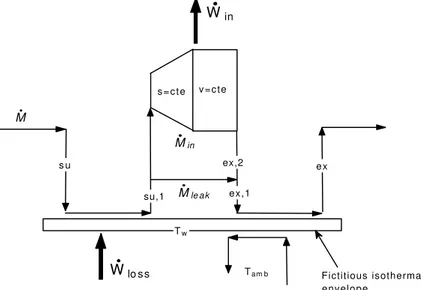
The scroll expander model has been previously proposed by the authors and partly validated by tests with water steam (Lemort et al., 2006). In this model, the evolution of the fluid state through the expander is decomposed into the following steps (as shown in Fig. 1):
• cooling-down in the supply port of the expander (su ? su,1);
• isentropic expansion from the supply pressure down to the adapted pressure imposed by the internal expansion volume ratio of the expander (su,1 ? ad);
• expansion at a fixed volume from the adapted pressure to the exhaust pressure (ad ? ex,2);
• mixing between suction flow and leakage flow (ex,2 ? ex,1) and • cooling-down or heating-up in the exhaust port (ex,1 ? ex).
Tw Tam b s u su,1 ex,2 e x Win Wlo s s M Mle a k Min Fictitious isothermal envelope ex,1 s = c t e v = c t e
Condenser and boiler models
The condenser is modeled as a one-zone heat exchanger. As shown in Fig. 2, this model accounts for:
i) a pressure drop located at the condenser supply (calculated by considering an equivalent orifice, whose diameter is dr,su,cd)
ii) ambient losses placed on water side at the condenser exhaust (calculated on the basis of a heat transfer coefficient AUcd,amb between the condenser and the ambience)
Fig. 2 Condenser model
The heat transfer is calculated by means of the ε-NTU method. The global heat transfer coefficient is calculated by assuming two resistances in series (water and refrigerant sides). As shown in Eq. (1), these two resistances could be calculated as a function of their respective mass flow rates (Cw and Cr are also parameters of the model)
8 , 0 8 , 0 1 1 r r w w r w cd M C M C R R AU & & + = + = (1)
The boiler modeling follows the same approach. However, one unique model is used here for each heat exchanger. The global model considers:
i) a pressure drop model at the HX1 supply and at the HX3 exhaust
Fig. 3 Boiler model Pump model
The volumetric pump is simply modeled by its swept volume and two supposed-to-be constant efficiencies: the isentropic (?pp,s) and the motor (?pp,m) efficiencies. The fluid heating-up introduced by the pump is neglected. The pump electrical consumption and the fluid swept flow rate are given by Eq. (2) and Eq. (3).
m pp s pp s pp m pp pp sh pp m W W W , , , , , , .η η η & & & = = (2) pp su r pp s pp pp su r pp s r v V X v V M , , max , , , , , . & & & = = (3) Cycle model
The whole cycle is simulated by interconnecting the models of its different components (Fig. 4). The modeling makes appear the following “causalities”:
I. For a given displacement, the pump imposes the refrigerant flow rate. II. The boiler imposes the fluid overheating and the pump exhaust pressure.
III. Provided its rotational speed is fixed, the expander imposes the boiler exhaust pressure. The condenser supply temperature is also imposed by the expander. IV. The condenser imposes the expander exhaust pressure and the pump supply
pressure. The subcooling at the condenser exhaust is considered as an input of the model, since it is imposed by the refrigerant charge.
Fig. 4 Bloc diagram representation of the Rankine cycle model
EXPERIMENTAL STUDY AND VALIDATION OF THE MODEL Description of the test bench
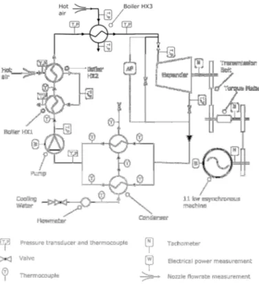
An experimental study is carried out on a prototype of ORC working with HCFC-123. The expander is originally an oil-free open-drive air scroll compressor, adapted in expander mode. Heat source consist in two hot air flows. The condenser is cooled by water.
The expander drives an asynchronous machine through a belt-and-pulley coupling. The asynchronous machine imposes the rotational speed of the expander. The expander mechanical power is determined by measuring simultaneously the rotational speed and the torque developed at the expander shaft. The refrigerant flow rate is determined from the energy balance over the condenser. The test bench is represented in Fig.5.
Description of the tests and reached performances
A series of 13 tests is carried out at a constant expander rotational speed (2200 rpm). A thermal power close to 15 kW is recovered at the boiler. Air enters into heat exchangers HEX2 and HEX3 at temperatures ranging respectively from 177°C to 189°C and from 137°C to 160°C. Its supply pressure doesn’t exceed 8.5 bar and the expander exhaust pressure doesn’t decrease under 1.5 bar. The expander develops a mechanical power ranging from 0.7 to 1 kW, with an overall isentropic effectiveness up to 65%.
Fig. 5 Schematic representation of the test bench
Validation of the ORC model and sub-models
Expander and pump model validation. The validation of the expander model is carried out
by imposing the supply and exhaust pressures, the supply temperature and the rotational speed as inputs of the model. Parameters are tuned in order to get equality between calculated and measured values of the flow rate, the mechanical power and the exhaust temperature. Fig. 6 (a) and (b) show the agreement between calculated and measured values after having identified the parameters (given in Fig. 6 (a)).
Fig. 6 Prediction of the refrigerant flow rate (a) and the expander shaft power and exhaust temperature (b)
According to the experimental measurements, the pump electrical consumption is of the order of 170W. In order to fit this value with the model, the efficiencies ηpp,s and ηpp,m are set to 0.4 and 0.5.
Heat exchangers models validation. The condenser and the boiler models are here validated
on the basis of 13 tests. Fig. 8 shows the comparison between the main simulated and measured outputs of this model. For the condenser, a very good agreement is observed for the enthalpy flow rate and condensing pressure. For the boiler, the results can be considered as acceptable.
(a) (b)
Fig. 7 Prediction of the condenser and boiler enthalpy flow rate (a) and pressure and pressure drop (b)
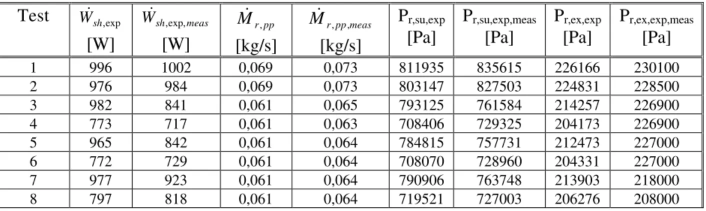
Cycle model validation. It appears that, after having been tuned, the global cycle model is
able to reproduce fairly well, amongst other things, the expander power, supply and exhaust pressure and the refrigerant flow rate (Table 2).
Table 2 Comparison between (some) values measured and predicted by the ORC model
Test W&sh,exp
[W] meas sh W& ,exp, [W] pp r M& , [kg/s] meas pp r M& , , [kg/s] Pr,su,exp [Pa] Pr,su,exp,meas [Pa] Pr,ex,exp [Pa] Pr,ex,exp,meas [Pa] 1 996 1002 0,069 0,073 811935 835615 226166 230100 2 976 984 0,069 0,073 803147 827503 224831 228500 3 982 841 0,061 0,065 793125 761584 214257 226900 4 773 717 0,061 0,063 708406 729325 204173 226900 5 965 842 0,061 0,064 784815 757731 212473 227000 6 772 729 0,061 0,064 708070 728960 204331 227000 7 977 923 0,061 0,064 790906 763748 213903 218000 8 797 818 0,061 0,064 719521 727003 206276 208000
9 933 877 0,060 0,063 787868 764184 220169 219500 10 717 703 0,060 0,061 713568 717174 217291 219500 11 982 1024 0,068 0,066 823563 800923 234995 217700 12 998 1056 0,073 0,067 837805 817999 242465 217700 13 1009 1055 0,077 0,068 849990 819594 249662 217700
Potential improvements of the system
Some potential improvements of the system (components characteristics and operating conditions) are stressed (see Fig. 8), among which:
• Beneficial higher pressure ratio imposed to the expander. This can be achieved by reducing both the condenser exhaust pressure and pressure drop.
• Reduction of the subcooling at the condenser exhaust to the minimum required in order to prevent any risk of pump cavitation (adequate charge of refrigerant).
• Increase of the expander effectiveness by reducing both the mechanical losses and the internal leakage and by optimizing the internal built-in volume ratio rv,in.
Fig. 8 Improvements of the cycle CONCLUSIONS
This paper proposes a model of ORC involving a relatively limited number of parameters. The agreement between values predicted by the model and experimental results show a fairly good agreement (for the cycle model as well as for the different sub-models).
The ORC model is then used to evaluate the potential increase of the system performances following some improvements of its components and operating conditions.
H& enthalpy flow rate (W) boil boiler
M& mass flow rate (kg/s) calc calculated
N rotational speed (Hz) cd condenser
P pressure (Pa) ex exhaust
Q& heat flux (W) exp expander
rv,in internal volume ratio (-) leak leakage
T temperature (°C) m mechanica
l
T torque (N.m) meas measured
Vs swept volume (m3) pp pump
v specific volume (m3/kg) r fluid
V& volume flow rate (m3/s) sh shaft
W& power (W) su supply
X pump capacity ratio (-) w water
BIBLIOGRAPHY
Hung, T.-C., 2001, Waste heat recovery of organic Rankine cycle using dry fluids,
Energy Conversion and Management, Vol. 42, pp. 539-553.
Kane, M., Larrain, D., Favrat, D., Allani, Y., 2003, Small hybrid solar power system,
Energy, Vol. 28, pp. 1427-1443.
Liu, B.-T., Chien, K.-H., Wang, C.-C., 2004, Effect of working fluids on organic Rankine cycle for waste heat recovery, Energy, Vol. 29, pp. 1207-1217.
Lemort, V., Teodorese, I. V., Lebrun, J., 2006, Experimental study of the integration of a scroll expander into a heat recovery Rankine cylce, Proc. 18th Int. Compressor Engineering Conference at Purdue, Purdue University, West Lafayette, C105.
Maizza, V., Maizza, A., 2001, Unconventional working fluids in organic Rankine cycles for waste energy recovery systems, Applied Thermal Engineering, Vol. 21, pp. 381-390.
Yamamoto, T., Furuhata, T., Arai, N., Mori, K., 2001, Design and testing of the Organic Rankine Cycle, Energy, Vol. 26, pp. 239-251.