Development of a Continuous Fluidic Reactor for the Photocatalytic Treatment
of Liquid Effluents
Pelzer M
1, Pirard SL
*1, Páez CA
1, Monbaliu JC
2and Heinrichs B
11Department of Chemical Engineering, Laboratoire Nanomatériaux, Catalyse, Electrochimie, University of Liège, Bât. B6, Allée de la Chimie 3, 4000 Liège, Belgium
2Center for Integrated Technology and Organic Synthesis, Research Unit MolSys, University of Liège, Liège (Sart Tilman), Belgium
*
Corresponding author: Pirard SL, Department of Chemical Engineering, Laboratoire Nanomatériaux,
Catalyse, Electrochimie, University of Liège, Bât. B6, Allée de la Chimie 3, 4000 Liège, Belgium, Tel: +32 0
366 35 40, E-mail: sophie.pirard@uliege.be
Citation: Pelzer M, Pirard SL, Páez CA, Monbaliu JM, Heinrichs B (2019) Development of a Continuous
Fluidic Reactor for the Photocatalytic Treatment of Liquid Effluents. J Mater Sci Nanotechnol 7(3): 301
Research Article Open Access
Volume 7 | Issue 3 Journal of Materials Science & Nanotechnology ISSN: 2348-9812
Environmental pollution has become a critical issue for our society. In the case of water pollution, advanced oxidation processes (AOP) has been investigated to remove the pollutants from water and to degrade and mineralize aqueous recalcitrant organic pollutants [1-5]. Heterogeneous semiconductor photocatalysis was proven to be a promising technology for the total mineralization of most organic pollutants by using natural or artificial light [6]. The most frequently used semiconductor is titanium dioxide, TiO2, due to its high oxidative potential, chemical stability, availability and its relatively low price [7]. In recent years, the sol–gel method has become an interesting approach for the synthesis of pure and modified TiO2 based materials with controlled nanostructures and surface properties [8-12].
Introduction
Abstract
The present study aims at developing a photocatalytic mesofluidic reactor for the continuous treatment of liquid effluents. The main idea to reach this objective is to deposit TiO2 thin films onto the inner walls of the fluidic reactor by using a sol-gel process. Glass and PFA (perfluoroalkoxy alkane polymer) are selected as construction materials for the fluidic reactor prototypes. In a first time, the operational conditions leading to a sufficient photocatalytic activity for methylene blue degradation are determined for TiO2 thin films deposited onto glass substrates through dip coating. The best photocatalytic activity is obtained for glass samples coated according to a procedure involving a withdrawing speed of the dipcoater of 60 mm min-1, a calcination temperature of 500 °C and a sol doped with 10 wt% of commercial TiO2 (Evonik P25). Next, to transpose this method to PFA substrates, it is slightly altered to take the specific TiO2-PFA adhesion requirements and the maximum temperature for PFA into account. Photocatalytic activity of the films is studied for the degradation of methylene blue in a batch reactor, as well as in a mesofluidic falling-film reactor. The deposition method onto PFA flat substrates is finally adapted to PFA capillaries. ESEM analysis reveals the presence of TiO2 on the inner walls of the capillaries and the methylene blue degradation tests shows their good photocatalytic activity. Thus the feasibility of deposing a photo-active TiO2 -film on the inner PFA walls of a mesofluidic capillary reactor by the sol-gel process for the degradation of methylene blue is proved.
Keywords: Photocatalysis; TiO2; Sol-Gel; Fluidic Reactor; Liquid Effluent Treatment
Because TiO2 is sensitive to only UV-visible light, the penetration of light within the reaction medium has to be maximized to improve the photocatalytic degradation of pollutants. This is the main problem of batch reactor commonly used for photocatalytic degradation reactions.
The use of fluidic reactor is a promising alternative to batch reactor [13-16], especially in photochemistry. Indeed, it allows combining the advantages of photochemistry and eliminating the problems related to the use of batch reactors, i.e. the low penetration of light within the reaction medium, gas-liquid mass transfer, solubility of oxygen in solution, and the transient nature of singlet oxygen, thus imposing long irradiation/reaction times, consequent energy input for active mixing and large excess of oxygen. Photochemistry in continuous-flow microreactors is now widely recognized as an enabling combination [17], providing major process assets arising from a much improved light penetration and accurate control of irradiation time, high mass and heat transfer, safe and efficient handling of transient species, and seamless scalability [18-22]. Numerous studies have already been performed [17,23-28]. This is especially interesting if the catalyst is in solid form and fixed on the walls of the micro-pipes, avoiding
Journal of Materials Science & Nanotechnology 2 separation steps that are necessary when the catalyst is dispersed as a powder in the reaction volume, as it is generally in traditional batch reactors [28].
Several studies have already been carried out to immobilize TiO2 on the inner walls of different microreactor supports [29]. Most of them concern the deposition of TiO2 in engraved microreactors [30-32]. Modelling and dynamic simulation of nanoparticle formation have shown the evolution of the solvent inside the droplet and the variation of particle size [32]. Electrochemical oxidation techniques of a titanium substrate have been tested to immobilize TiO2 in a microreactor fabricated on a metal-titanium foil, in a two-steps process including an anodization and a hydrothermal treatment [33]. Rebrov et al. have synthesized a doped-TiO2 film on the inner walls of a silica capillary [34]. Concerning coating of polymers capillaries, more particularly PFA capillaries, several studies have been conducted on capillaries of different internal diameters. Immobilization of the photocatalyst has been performed from an aqueous suspension of TiO2 particles with different concentrations, and the degradation of phenol has been studied [35,36]. The use of photocatalyst slurry in centimeter scale reactors rather than microreactors to combine advantages of high surface area, sufficient illumination and high-throughput without clogging, has also been highlighted by Heggo et al. More recently, commercial ZnO nanoparticles have been deposited in the inner wall of a fluoropolymer using a low energy ultrasound bath under mild conditions and used for selective conversion of aromatic alcohols to aldehydes [37].
The objective of this work is to provide simple solutions for the construction of affordable efficient photocatalytic flow device with heterogeneisation of TiO2 on the inner wall of the fluidic device for the photocatalytic treatment of aqueous effluents. To achieve this goal, TiO2 must be immobilized on the inner walls of the reactor. Different materials were considered as support for the coating: glass and perfluorinated polymer (PFA). The ultimate goal of this work is to be able to coat a PFA capillary with a photocatalytic layer. Indeed, this material is well adapted for the intended application since it is flexible, and therefore easily wrapped around a light source, UV-transparent, resistant to a wide variety of organic compounds and operational conditions, and economically affordable. In contrast to other previous studies, the deposition of TiO2 is performed by the sol-gel process in this work. Once the catalyst has been deposited, its photocatalytic activity is tested for degradation of a model pollutant which is methylene blue (MB).
Experiments
Synthesis and Characterization of Undoped TiO2 Catalysts: The first series of films is made from a sol prepared according to a
method proposed by Páez et al. [38]. Subsequently, this sol is called “sol I”. A first solution is obtained by adding 38 mL of titanium (IV) tetraisopropoxide (TIPT, ≥ 97%, Aldrich) to 206 mL of 2-methoxyethanol (≥ 99.5%, Merck). A second solution is obtained by adding 5.2 mL of deionized water to 206 mL 2-methoxyethanol. Both solutions are stirred for 1 h at room temperature. Then, 25 mL of the water-containing solution is added to 25 mL of the solution containing the TIPT. The sol is then stirred for 30 minutes at room temperature before being used for deposition.
Thin films of TiO2 are deposited by dip-coating (Dip-coater KSV-DC, KSV Instrument) in the sol synthesized as described just above on glass slices without alkalis since it has been shown by Malengreaux et al. that thin films of TiO2 deposited on such substrates exhibit an activity unlike to films deposited on soda-lime glass [39,40]. Furthermore, the high superhydrophilicity of the TiO2 photocatalyst allows the formation of a stable homogeneous falling liquid along the glass sheets [3].
Three layers are deposited by dip-coating on each sample with a withdrawing speed equal to 60 or 200 mm min-1. Each layer is
dried for 1 h at 150 °C. Then calcination for 1 hour in air at 500 °C with a temperature ramp of 10 °C min-1 is performed. Both sides
of the glass slices are covered with a thin film and the total area of the film is 27.5×10⁻⁴ m². The thickness and roughness of the films
are measured by profilometry (Veeco, Dektak 8 Stylus Profiler).
Absorbance spectra are determined by spectrophotometry (Thermo Scientific Genesys 10S UV-Vis Spectrophotometer) in the re-gion of 200 to 900 nm, with a pitch of 1 nm. The crystalline structure of TiO2 films is studied by grazing incidence X-ray diffraction. The diffractometer (Bruker D8) uses copper Kα ray and operates at 40 kV and 40 mA at an incidence angle of 0.3o.
Synthesis and Characterization of TiO2 Catalysts Doped with P25: In order to get a crystalline phase without any high
tempera-ture calcination step, the synthesized catalyst is doped with a commercial TiO2: the Evonik P25 [40]. By doping the sol with P25, the crystalline phase of P25 should improve the catalytic activity.
Therefore a second set of films is prepared by modifying sol I. The sol used here (called sol II) is prepared according to the same synthesis method as sol I, but 10% wt of P25 is added to the solution. For the synthesis of sol II, the procedure followed for the preparation of the two starting solutions is identical to that of sol I. Next, 0.1 g of P25 is added to 25 ml of the titanium tetraiso-propoxide solution (TIPT) and 2-methoxyethanol. Thus, P25 and TiO2 solution are in a mass ratio of 10%. This mixture is left for 1 h in an ultrasonic bath and is then stirred for 24 h at 60 °C. Finally, in the same way as for sol I, 25 mL of the solution contain-ing water and 25 mL of the solution containcontain-ing TIPT and P25 are mixed and stirred for 30 min before use. The films are depos-ited according to the same protocol as for sol I.
Journal of Materials Science & Nanotechnology 3
As for the first set of samples, the thickness and roughness of films are measured with a profilometer, the absorbance spectra are determined by spectrophotometry and the crystalline structure of TiO2 films is studied by grazing incidence X-ray diffraction.
The MB (methylene blue) concentration of the solution to be degraded is 1.1×10⁻⁵ M. 60 mL are placed into a tube with a capacity of
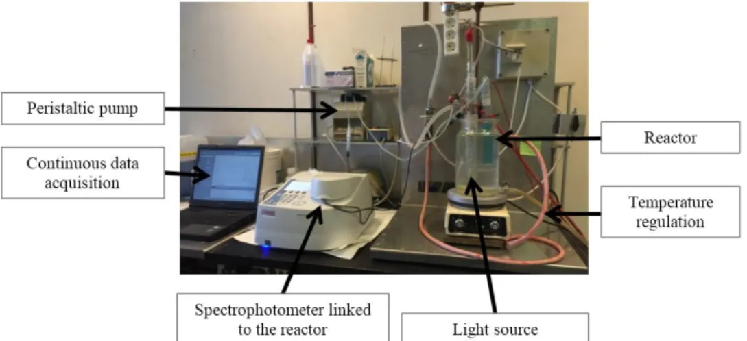
100 mL and shaked thanks to a magnetic stirring bar. A Xenophot lamp (Xenophot, HLX 64625, 12 V, 100 W, Osram) which radiates mainly in the visible range (emission spectrum presented in Figure 1) is inserted in a double-shell pyrex tube that allows the lamp to be cooled. Tubes containing the solution and the lamp are both immersed in a thermostatically controlled tank at 18 °C. The tank is covered with an aluminum sheet in order to isolate the reaction medium from the room light. The spectrophotometer quartz cell is connected (input and output) to the reactor and a peristaltic pump allows to continuously withdraw the solution from the reaction medium and to continuously reject it after passing through the cell. The cell remains fixed in the spectrophotometer for the duration of the experiment and the absorbance measurements are performed every 15 seconds. The assembly is shown in Figure 1.
A calibration curve has to be established using several solutions of different MB concentrations precisely known. In the degradation test, the baseline is running for 10 minutes from 44 mL of deionized water. Then, 6 mL of a solution of 8×10⁻⁵ M MB is added to the
reaction volume and the lamp is switched on. The total volume is 50 mL and the initial concentration, noted C0, is equal to 10-5 M.
The Xenophot lamp is used at maximum power for uncatalyzed degradation of MB. In order to remove the visible contribution of degradation, a visible filter is developed: MB itself is an ideal candidate. Therefore, the water bath in which is immersed the tube of the lamp and the tube containing the solution to be degraded is replaced by a concentrated solution of MB. The principle is as follows: the emitted radiation meets at first the filter solution. MB of this solution absorbs the part of the radiation that would be absorbed by the reaction medium in a case without any filter. Therefore, when the radiation reaches the reaction medium, wave-lengths that degrade the MB by non-catalytic reactions have already been absorbed. The influence of the MB filter concentrations has been previously studied and the optimal concentration was found to be equal to 2.3 × 10⁻⁵ M.
Then the catalytic degradation of MB is studied with continuous measurements in the previously described reactor by applying the MB filter previously developed. The catalyst-coated glass substrates are simply immersed in the tube containing the MB solution. A glass slice without any catalyst is also tested. It is referenced as "Without cata" sample.
At first, the absorbance measurements are recorded in the dark for 60 minutes to ensure that the concentration is stable before starting the degradation. Then, the Xenophot lamp is switch on and the measurements are performed for 45 minutes.
Synthesis and Characterization of Undoped TiO2 Catalysts: Before depositing a film on the inlet wall of a PFA capillary, the
sol-gel method previously used for glass has been transposed to another substrate which is PFA slice.
The sols used for deposits on PFA are identical to the sols synthesized for the coating of glass substrate (sol I and sol II). Thin films of TiO2 is also deposited by dip-coating on PFA slices.
An additional sample is synthesized, following the same coating procedure, but with a calcination step at 230 °C instead of 500 °C, in order to get synthesis conditions as similar as possible to the conditions used later with the PFA since it does not support high temperature calcination.
Design of a Photocatalytic Reactor for Continuous MB Degradation Measurements
Figure 1: Emission Spectrum of the Xenophot Lamp, Compared to an Halogen Lamp
Journal of Materials Science & Nanotechnology 4 It has been shown that a heat treatment by heating PFA substrate in an oven at 150 °C for 1 hour before producing the layers by dip-coating on cooled slides at room temperature gives good adherence results.
The coating of the PFA substrate after heat treatment is then done following the same procedure as for the coating of glass. The withdrawing speed is 60 mm min-1 because it leads to a best activity on the glass substrate. However, the calcination procedure
must be adapted to the substrate. Indeed, PFA cannot be heated at a temperature above 260 °C. So the calcination is carried out at 230°.
The absorbance spectra of films on PFA substrates were determined by spectrophotometry and the crystalline structure of TiO2 films is studied by grazing incidence X-ray diffraction. However, it is not possible to determine the thickness and roughness of the films by profilometry, due to the high roughness of PFA leading to a too noisy signal.
Two types of microreactors have been designed. The first one, called “film reactor”, uses a film flow along a window coated with the catalyst and illuminated. The second one, called “capillary reactor”, consists of a capillary wrapped around a lamp and whose inner surface is coated with the catalyst.
Film Reactor: The flow takes place between two flat and parallel surfaces. These surfaces consist in windows that allow irradiation
of the solution. In addition, one of the windows is covered with TiO2 catalyst. This window consists of glass or PFA coated slices, as described before (Figure 2).
Photocatalytic Activity with PFA Substrate: Films coated on PFA substrate are first tested for the MB degradation in the batch
reactor described before.
Design of Photocatalytic Fluidic Reactor
Figure 2: Experimental Tank Reactor for MB Degradation without Catalyst, for Continuous Measurements
Journal of Materials Science & Nanotechnology 5
The MB degradation was first tested in the film reactor with coated glass slices.
Capillary Reactor: The final goal of this study is the design of a capillary reactor, involving first the deposition of TiO2 on the inlet
surface of capillary by using the synthesis methods previously developed. Then, the microreactor is tested for MB photocatalytic degradation.
The PFA capillaries have an internal diameter of 800 μm and are cut into sections of 30 cm long. The dip-coating method on PFA slides is not suitable for the internal surface of capillaries. So coatings are obtained by flowing the sols in the capillaries, thanks to a syringe pump, in order to reproduce the method developed previously by dip coating as accurately as possible.
It has been shown that PFA requires a heat treatment to activate its surface before being coated. The capillaries are heated at 150 °C for 1 hour. During the heat treatment, a flow of air passes through the capillaries. The first step of the deposition is to inject the sol into the capillary with a speed of 200 mm min-1. Once the capillary is filled, the solution is immobilized for 20 s. Then, the solution
is removed by aspiration into the syringe, with a speed of 60 mm min-1.
Then the syringe pump continues to draw air for 2 min to allow the evaporation of the solvent. Between each layer, the capillary is dried in an oven at 150 °C for 1 h and optionally calcined at 230 °C. The capillary reactor is highlighted on Figure 3.
Characterization of Undoped TiO2 Catalysts: The thickness and the roughness of the films measured by profilometry are presented
in Table 1. Because the roughness of films obtained from sol I is very weak, the corresponding results are not included. It can be shown that the thickness of films increases with withdrawing speed. It can also be shown that calcination does not significantly influence the thickness. After calcination, the thickness does not vary or slightly decreases, because the structure is contracted after structural rearrangements resulting from the formation of new Ti-O-Ti bonds with the concomitant disappearance of the organic groups remaining in the matrix or from crystallization of TiO2 in its anatase form.
The reactor is composed of 7 rectangular superposed layers. In the middle of each layer, a window is cut in order to allow an irradiation through the internal volume of the reactor. Figure 3 shows the reactor. Thanks to this design, the surface to volume ratio of the reactor is improved compared to the thank reactor. Indeed, it goes from 0.061 m² L-1 (tank reactor) to 0.158 m² L-1
(film reactor). Pipes are isolated from the light of the room in order to avoid MB degradation due to ambient light. Furthermore, the tank previously used is removed to minimize the volume of solution outside the reactor. The mixing of the solution is ensured by pulsations of the pump and by connections between the different parts of the circuit. The filling of the circuit is done simply by opening the circuit at a connection, then by injecting the solution at one end of the open circuit until the excess of solution comes out from the other end.
In order to obtain a MB degradation in the light large enough to be distinguished from the concentration decrease in the dark, the lamp used for degradation tests is a HQL Deluxe 125 W Osram lamp (called Deluxe lamp afterwards), whose emission spectrum is characteristic of a mercury lamp (emission spectrum presented in Figure 4). Indeed, it was previously proved that the degradation in the light was not significantly different from the degradation in the dark with the Xenophot lamp in the film reactor. Preliminary tests have shown that the degradation is more important with the Deluxe lamp than with the Xenophot lamp. The change of slope of the degradation curve when the lamp is switched on is clearly distinguishable. Just like the Xenophot lamp, the Deluxe lamp is filtered to avoid degradation due visible radiation.
Figure 4: Emission Spectrum of the Deluxe Lamp with or Without Filter
Results and Discussion
Journal of Materials Science & Nanotechnology 6
Sample
Withdrawing
Speed TemperatureCalcination Thickness
1 layer 2 layers 3 layers (mm min-1) (oC) (nm) (nm) (nm) 60A 60 NC 24 52 130 60B 60 NC 19 53 119 60C 60 NC 5 51 87 16 52 112 60D 60 500 17 53 116 60E 60 500 11 52 101 60F 60 500 14 52 108 14 52 108 200A 200 NC 30 79 187 200B 200 NC 27 83 200 200C 200 NC 33 105 208 30 89 198 200D 200 500 31 97 203 200E 200 500 30 93 201 200F 200 500 20 95 202 27 95 202 NC: Non Calcined
Table 1: Thickness of Films on Glass Substrate from Sol I
The crystalline structure of TiO2 films is studied by grazing incidence X-ray diffraction. The X-ray spectra obtained for TiO2 films made from sol I under different experimental conditions are given in Figure 5. No peak is detected for non-calcined samples. On the other hand, samples calcined 500 °C for 1 h show a characteristic peak of TiO2 in the anatase form. Peak intensity for a withdrawing speed of 200 mm min-1 is greater than with a withdrawing speed of 60 mm min-1. Non-calcined films do not show peaks on their
X-ray spectra. The highest temperature encountered during the synthesis of these samples is 150 °C, corresponding to the drying temperature. A temperature of 150 °C is not high enough to promote crystallization of TiO2 [38]. However, because of very similar absorbance spectra between uncalcined and calcined samples, it is possible that non-calcined films contain undetectable anatase nanocrystallites due to their very small size. The intensity of the peaks observed depends both on the amount of crystalline phase present and on the thickness of the film. In grazing incidence, the angle of incidence is very low and remains constant. The depth of penetration is therefore also low and constant.
An absorbance spectrum is determined by spectrophotometry. Figure 4 gives an example of absorbance spectra obtained for three samples (sol I, 60 mm min-1, not calcined) and for a slice of uncoated glass. The absorbance spectra show good reproducibility
between the three samples synthesized under the same conditions. It can be seen that the TiO2 films absorb for wavelengths smaller than about 400 nm. This means that a lamp with UV radiation is needed to activate the catalyst.
Journal of Materials Science & Nanotechnology 7
Sample
Withdrawing
speed temperatureCalcination Thickness Rugosity
1 layer 2 layers 3 layers 1 layer 2 layers 3 layers
(mm min-1) (oC) (nm) (nm) (nm) (nm) (nm) (nm) D60A 60 NC 53 119 230 29 63 75 D60B 60 NC 47 125 223 37 69 83 D60C 60 NC 36 118 165 35 73 89 45 121 206 34 68 82 D60D 60 500 49 78 176 12 28 77 D60E 60 500 49 82 147 44 24 98 D60F 60 500 28 47 130 24 37 83 42 69 151 27 30 86 D200A 200 NC 123 254 319 61 96 98 D200B 200 NC 124 224 326 59 98 109 D200C 200 NC 112 239 330 63 85 102 120 239 325 61 93 103 D200D 200 500 41 - 234 39 - 115 D200E 200 500 47 81 232 39 47 99 D200F 200 500 54 103 249 44 60 118 47 92 238 41 54 111 NC: Non Calcined
Table 2: Thickness of Films on Glass Substrate from Sol II
If the thickness of the film increases, the amount of material probed is greater (as far as the thickness of the film does not exceed the depth of penetration) and a larger number of crystallites can be detected, which increases the intensity of the peaks [33]. This explains that the intensity of the peak increases as the withdrawing speed increases, since the thickness of the film increases with withdrawing speed.
The thickness and roughness of samples prepared from sol II were measured by profilometry.
The values obtained are shown in Table 2. As for sol I, the measured thickness increases with the withdrawing speed. For sol II, calcination significantly influences the thickness: the latter decreases after calcination due to structural rearrangements. Furthermore, films prepared from sol II have a greater thickness than those from sol I. The profilometry measurements reveal the rough nature of the films prepared from the sol II. This characteristic is important because this allows increasing the specific surface area of the film. Thus, for the same apparent surface of catalyst, the surface available for reaction is larger for films made from sol containing P25 (sol II).
The films obtained from sol II are studied by grazing incidence X-ray diffraction. X-ray spectra obtained are shown in Figure 6. All samples prepared from sol II show a characteristic peak of TiO2 in anatase form. For non-calcined and samples calcined at 230 °C, the peak intensity is very low and is mainly due to the presence of P25 in the film. Samples calcined at 500 °C have a high intensity peak whatever the withdrawing speed. In the case of sol I, the intensity of the peak increases with the withdrawing speed and therefore with the thickness. However, the same trend is not found in the case of sol II since the two peaks of the samples calcined at 500 °C are similar in intensity while the thicknesses differs. It is possible that the thickness of the sample made with a speed of 200 mm min-1 is greater than the penetration depth of the beam and therefore the entire thickness is not probed. However,
the intensity of the peak should then be at least equal to that of the peak of the sample synthesized from sol I with the same speed. The peak intensity is however lower. Part of the explanation could come from the roughness of samples from sol II which probably affect peak intensity. Indeed, the profilometry analysis showed that the films containing P25 (sol II) have a high roughness, which is not the case for samples from sol I. Interpretations of peak intensity should then be done carefully.
Characterization of TiO2 Catalysts Doped with P25: The previous section shows that TiO2 synthesized from sol I does not
exhibit crystalline phase if there is no calcination. TiO2 must be however crystalline to have a photocatalytic activity. In the case of a glass substrate, calcination at high temperature is not a problem. However, other materials such as PFA, which is the material of the capillaries used in microreactors, would not withstand such a heat treatment. Therefore, the goal now is to synthesize TiO2 catalysts with a crystalline phase without calcination at high temperature. To reach this goal, the synthesized catalyst is boosted with commercial TiO2, Evonik P25.
Journal of Materials Science & Nanotechnology 8
A calibration curve has to be established for the MB degradation with the Xenophot lamp. The calibration line obtained by absorbance recording is defined by the following equation, where C is the MB concentration and A the absorbance:
Then the catalytic degradation of MB has been studied with continuous measurements in the previously described reactor by applying the MB filter previously developed. Results are given in Figure 7. Two areas have to be distinguished on these curves. From 0 to 45 min, the system is in the dark and from 45 to 90 min, the lamp is on. Results show that the concentration in the dark decreases first and then stabilizes. This can be explained by an adsorption of MB on the surface of the catalyst or on the surface of the glass. Under illumination, degradation occurs for all catalysts. However, the conversion obtained after 45 min under light is low, and does not exceed 5% in the best case.
Regarding the sample “without cata”, a slight degradation occurs. This degradation is probably due to a residual part of the visible radiation that would not have been absorbed by the filter.
For a reaction order equal to η, the variation of concentration as a function of time is given by:
C = 1,27.10
-5A + 1,23.10
-7 (1)Design of a Photocatalytic Reactor for Continuous Measurements of MB Degradation on TiO
2Coated
Glass Slices
Figure 6: Absorbance Spectra of a Non Coated Glass Slice and of Glass Slices Coated From Sol I, Non
Calcined and with a Withdrawing Speed of 60 mm min-1
(2) app
dc k C
dt
η−
=
Journal of Materials Science & Nanotechnology 9
The mass balance for the reactor is the following:
After several transformations and defining a parameter α as
the mass balance becomes:
with Vcirc is the volume of the circuit (L).
This expression means that the actual degradation rate (r(t)) is greater than the degradation rate observed in the system (= reactor + circuit) (term -dC(t)/dt).
The apparent constant kapp takes into account the activity of the catalyst and the intensity of the radiation, while parameter α takes into account the geometry of the tank reactor, that is the fact that a fraction of the solution is in the dark in the pump circuit. A factor k’ can be defined as the true kinetic rate constant of the reaction (s-1). For the reactor tank, its expression is:
Then, using a first order apparent kinetic law (C = C0 exp(-kapp t) or ln(C/C0)= -kapp t), the kinetic equation is given by:
where n is the number of moles of MB in the reactor (mol), t is the illumination time (s), Fin is the molar flow rate of MB that enters the reactor and leaves the circuit (mol s-1), F
out is the molar flow rate of MB leaving the reactor and entering the circuit (mol s-1), r
is the degradation rate of MB in the reactor (mol L-1 s-1) and V
r the volume of the reactor (L).
where C is the MB concentration, kapp the apparent kinetic constant and t the illumination time. In several papers dealing with the degradation of MB by TiO2 photocatalysis [35,38], it has been shown that the reaction follows a first order kinetics. A value η = 1 is therefore retained. In order to establish an equation of the degradation rate of MB in the reactor, it is necessary to model the reactor. Indeed, the reactor cannot be simply assimilated to a discontinuous perfectly mixed tank because there is permanently a part of the reaction volume which is pumped out of the reactor to the spectrophotometer cell which is not illuminated. The reactor diagram is shown in Figure 8.
Figure 8: X-Ray Spectra of Substrate Coated from Sol II
(3) ( ) ( ) ( ) ( )V in out r dn t F t F t r t dt = − −
1
circ rv
v
α
= −
(4) ( ) dc r t dt = −α
(5) 0( )
appexp(
)
appk
r t
C
k t
α
=
−
(6) 'k
appk
α
=
(7)Journal of Materials Science & Nanotechnology 10
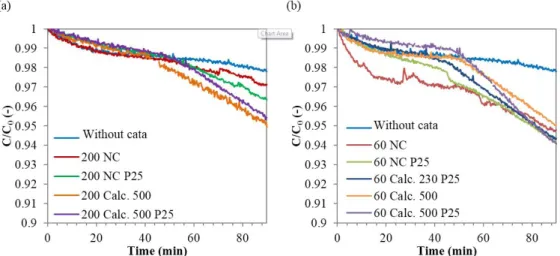
Figure 9 presents the evolution of logarithm of the MB concentration as a function of time. It exhibits straight lines that are in agreement with a first order kinetic law and Table 3 gives the values of the kapp and k’ kinetic constants. Results show that a sample made with a withdrawing speed of 60 mm min-1 gives better performance than the corresponding sample with a speed of 200 mm min-1. In addition, calcination improves the activity of the catalyst. In particular, calcination at 500 °C further improves the activity
compared to calcination at 230 °C. Doping with P25 also increases the activity of the catalysts. More specifically, for samples made with a speed of 60 mm min-1, the activity of the non-calcined sample doped with P25 (60 NC P25) is equivalent to that of the
undoped sample calcined at 500 °C (60 Calc 500). Doping with P25 therefore allows in this case increasing the activity in the same way as calcination at 500 °C.
In conclusion, the system developed allows continuously measuring the absorbance, and therefore the MB concentration of the solution. Moreover, thanks to a suitable filter, the visible radiation can be eliminated which allows to evaluate the catalytic contribution of the degradation only. The degradation of MB corresponds to a first order kinetic law, but the observed variation of concentration is not equal to the reaction rate. Indeed, compared to the model of the ideal discontinuous stirred tank reactor, it must be multiplied by a corrective factor in order to take into account the volume of the external circuit necessary for the absorbance measurement. A catalytic activity is detected for all samples, even those that are not calcined, and the catalytic activity is improved by the presence of P25 in the films.
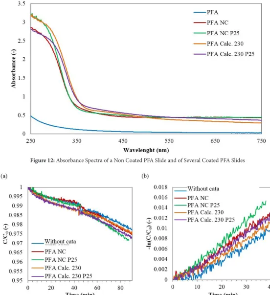
Characterization of undoped TiO2 catalysts: Absorbance spectra are determined spectrophotometrically in the region of 250 to
750 nm, with a step of 1 nm. Spectra are shown in Figure 10. The spectrum of PFA slice without TiO2 makes it possible to check that the PFA is transparent to the UV (λ <380 nm). As in the case of films deposited on glass slices, calcination leads to a shift of the absorption spectrum to higher wavelengths.
The reaction rate is finally written:
It would be interesting to compare the different catalysts in order to study the influence of withdrawing speed during dip-coating, of calcination, and of doping with P25 on MB degradation.
(8)
' 0
( )
exp(
app)
r t
=
k C
−
k t
Figure 9: MB Degradation In The Tank Reactor With Several Catalytic Coated Grass Slides (a) with a
Withdrawing Speed Of 200 mm Min-1 and (b) with a Withdrawing Speed of 60 mm min-1
Sample kapp k' Sample kapp k'
(x10-5 s-1) (x10-5 s-1) (x10-5 s-1) (x10-5 s-1) (x10-5 s-1) Without Cata. 0,2 0,3 200 NC 0,4 0,5 60 NC 0,9 1,0 200 NC P25 0,9 1,0 60 NC P25 1,3 1,5 60 Calc. 230 P25 1,5 1,7 200 Calc. 500 1,2 1,4 60 Calc. 500 1,3 1,4 200 Calc. 500 P25 1,2 1,4 60 Calc. 500 P25 1,8 2,0 The nomenclature for sample name is the following: withdrawing speed, NC (non calcined) or calc. (calcined) following by the calcination temperature, P25 means that the sample has been doped with P25.
Table 3: Kinetic Rate Constant for MB Degradation with the Xenophot Lamp in the Tank Reactor for
Coated Glass Substrate
Journal of Materials Science & Nanotechnology 11
The crystal structure of the films was studied by X-ray diffraction with the same parameters as for glass slices. Results show no peak characteristic of anatase or rutile. However, this does not mean that there is no crystalline phase. Tiny nanocrystallites that are difficult to detect could be present, in particular in films calcined at 230 °C.
Photocatalytic Activity with PFA Substrate: Films on PFA slices are tested for MB degradation in the tank reactor. Results are
given in Figure 11. The reference sample is an uncoated PFA slice, referenced as "Without cata". Several observations are the same than in the case of glass slices. First, the degradation curves have the same trend. In the dark, the MB concentration first decreases and then stabilizes. In the light the concentration decreases again. The conversion obtained after 45 minutes is also low. Finally, the test with the reference sample highlights low degradation, due to catalytic phenomena in the visible range. However, non-catalytic degradation under visible light is significant compared to PFA slices coated with catalyst.
The degradation can be also represented by a first order kinetic law (Figure 11). Kinetic constants k’ are calculated from the apparent constants kapp according to the previous reactor model (Table 4).
The kinetic constant k’ for the reference sample on PFA is similar to that of the reference sample on glass (0.3×10⁻⁵ s-1). Tests on PFA
or glass slices in the same reactor are therefore coherent. In general, catalysts on PFA have kinetic constants smaller than catalysts on glass. The conversion observed after 45 min on coated PFA is lower too.
Figure 10: Scheme of the Tank ReactorII
Figure 11: First Order Kinetic Law For MB Degradation In The Tank Reactor With Several Catalytic Coated Grass
Slides (a) With a Withdrawing Speed of 200 mm min-1 and (b) with a Withdrawing Speed of 60 mm min-1
Sample kapp k' (x10-5 s-1) (x10-5 s-1) Without Cata. 0,4 0,4 PFA NC 0,5 0,6 PFA NC P25 0,6 0,7 PFA Calc. 230 0,4 0,5 PFA Calc. 230 P25 0,5 0,6
Table 4: Kinetic Rate Constant for MB Degradation with the
Journal of Materials Science & Nanotechnology 12 The catalysts deposited on PFA slices give similar performances. Indeed, the kinetic constants are all in the same order of magnitude. Regarding doping, the same trend is found than for glass slices: P25 doping improves the activity of the catalyst. On the other hand, for PFA blades, calcination at 230 °C does not significantly improve the degradation.
Film Reactor: Samples on glass slices coated at a speed of 60 mm min-1 were tested in the film reactor with the Deluxe lamp.
Degradation curves obtained and the corresponding straight lines for a first order kinetics are given in Figure 12. Kinetic rate constants are given in Table 5. For the reference sample (without any catalyst), MB concentration stabilizes after 45 minutes in the dark. Then, the concentration remains constant under light, meaning that no degradation reaction takes place, even due to the visible light. This observation is not consistent with the previous ones. Indeed, in the case of the tank reactor, the Deluxe lamp leaded to low degradation with the reference, indicating that part of the visible radiation reached the solution despite the filter. In Figure 12, the stabilization is not reached after the 45 minutes in the dark for samples coated with catalyst. For non-calcined samples, there is no significant change in the slope when the light is switched on. The decrease in concentration under light may therefore be due to both a catalytic degradation and an adsorption of MB in the pump pipe. As previously observed, for the samples calcined at 500 °C, the catalytic activity is obvious. In addition, the activity is improved with doping with P25. Samples calcined at 230 °C on a glass substrate and on a PFA substrate, have also been tested in the film reactor with the Deluxe lamp. Results are given in Figure 13 and Table 5. For samples calcined at 230 °C, although a change in concavity is observed, the degradation cannot be attributed only to catalytic phenomena. However, if non-catalytic degradations are the same whatever the catalyst, the activities can be compared for each catalyst. Figure 13 (b) shows that the undoped film gives the best degradation, contrary to case in the tank reactor. As for the films doped with P25, substrates in glass or in PFA give a similar activity.
Design of Photocatalytic Fluidic Reactor
Figure 12: Absorbance Spectra of a Non Coated PFA Slide and of Several Coated PFA Slides
Figure 13: MB Degradation in the Tank Reactor with Several Catalytic Coated PFA Slices with a Withdrawing Speed of
Journal of Materials Science & Nanotechnology 13
Characterization of the Coated Capillary: The TiO2 layer was highlighted by measurements at ESEM (Environmental Scanning
Electron Microscope), on sections of capillaries cut lengthwise in order to obtain hollow half cylinders. The images obtained show a heterogeneous layer where the TiO2 is in the form of aggregates (Figure 14). It is not possible to see a layer whose thickness in around 100 nm because the electron beam melts the polymer. Elemental analysis detected carbon and fluorine on all samples from the PFA substrate, and titanium and oxygen on the coated sample, highlighting the presence of TiO2.
Photocatalytic Tests: Degradations obtained with the Deluxe lamp and the corresponding curves for a first-order kinetics
are given in Figure 15. The kinetic constants are given in Table 6. As for the film reactor, stability is still not achieved after 45 minutes in the dark. Moreover, for the capillary reactor, even the Deluxe lamp does not allow obtaining a significant slope change during illumination, meaning that no further activity is observed. The opposite phenomenon is observed, meaning that the slope obtained under light (kapp) is smaller than the slope observed over the last 20 minutes in the dark (kblack) (Table 6). Therefore the quantification of the photocatalytic activity of the different catalysts is difficult because the measured degradation is due to both catalytic and adsorption phenomena. However, the catalysts can be compared if it is assumed that the extent of degradation due to MB adsorption is the same for each sample.
Capillary Reactor
Sample kapp k'
(x10-5 s-1) (x10-5 s-1) Glass Without Cata. 0 0
(Glass) 60 NC 2,3 4,2 (Glass) 60 NC P25 2,1 3,8 (Glass) 60 Calc. 230 P25 2,1 3,9 (Glass) 60 Calc. 500 8,1 14,9 (Glass) 60 Calc. 500 P25 10,7 19,7 PFA Calc. 230 4,6 8,4 PFA Calc. 230 P25 2,7 5,0
Table 5: Kinetic Rate Constant for MB Degradation with the Deluxe
Lamp in the Film Reactor for Coated Glass or PFA Substrate
Figure 14: MB Degradation in the Film Reactor with Different Catalysts on Glass Slices with a Withdrawing Speed of 60
mm min-1 (a) from 0 to 45 min in the Dark, and from 45 to 90 min with the Deluxe Lamp (b) First Order Kinetics
Sample kblack kapp k‘
(x10-5 s-1) (x10-5 s-1) (x10-5 s-1) Cap. Without Cata. 2,8 1,1 42
Cap. NC 2,5 1,2 46
Cap. NC P25 2,1 1,5 56
Cap. Calc. 230 3,4 2,9 111
Cap. Calc. 230 P25 2,7 2,1 79
Table 6: Apparent and True Kinetic Constant for MB Degradation with
Journal of Materials Science & Nanotechnology 14
Figure 15: MB Degradation in the Film Reactor with Different Catalyst on Glass Slices or on PFA Slices with a Withdrawing Speed
of 60 mm min-1. (a) From 0 to 45 min in the Dark, and from 45 to 90 min with the Deluxe Lamp. (b) First Order Kinetics
Microreactor Models: In order to be able to estimate the expression of the reaction rate in microreactors, it is necessary to establish
a model, which is the same for both film and capillary reactors. The experimental setups are schematically represented in Figure 16. As for all reactors considered in this study, the reference sample exhibits the smaller activity. Then both uncalcined samples have similar activity which is slightly higher than activity of the uncoated sample. Calcination at 230 °C improves the activity and, as in the same way than PFA slices in the film reactor, the calcined and undoped sample shows a better activity than the sample calcined and doped with P25.
In order to know the type of flow in the reactor, it is necessary to calculate the Peclet number, Pe.
Figure 16: SEM Images of Cut Capillary (a) without Catalyst and (b), (c), (d) with Catalyst (Sample Calcined at 230 oC)
(9) c
vL
Pe
D
=
Journal of Materials Science & Nanotechnology 15
Reactor Comparison: In order to be able to estimate the expression of the reaction rate in microreactors, it is necessary to establish
a model, which is the same for both film and capillary reactors. The experimental setups are schematically represented in Figure 16. where ν is the fluid velocity (ms-1), L
c is the reactor characteristic length (m), and D the coefficient of diffusion. For a film reactor,
Lc is the distance between the two windows, and for a capillary reactor, Lc is the diameter. For liquids, the order of magnitude of the diffusion coefficient is 10-9 m2 s-1. The calculated Peclet number for film and capillary reactors is 2.4 ×10³ and 7.2 × 10⁵, respectively.
High Peclet numbers correspond to a piston flow. So the model of film and capillary reactors is based on a tubular reactor. The mass balance requires the definition of a geometric parameter:
An expression of the evolution of concentration as a function of time obtained experimentally is also required:
This expression is similar to the expression obtained for the tank reactor. As for a tank reactor, a factor k’ can be defined as the true kinetic rate constant (s-1). For film and capillary reactors, its expression is:
The reaction rate becomes:
Different reactors have been used for photocatalytic degradation tests: tank, film and capillary reactors. These three types of reactors have different characteristics such as the internal reactor volume, the total volume, or the catalyst surface. All corresponding data are shown in Table 7.
However, the observed degradation depends on the illuminated catalyst surface. It would be interesting to define a specific rate rA (mol m-2 s-1) independent of the catalyst surface:
For these reactor types, the model lead to the same reaction rate expression r tot
V
V
β
=
(10) 0( )
appexp(
)
appk
r t
C
k t
β
=
−
(11) 'k
appk
β
=
(12) ' 0( )
exp(
app)
r t
=
k C
−
k t
(13)Parameter Units Tank Reactor Film Reactor Capillary Reactor
Vr mL 45 6 0,14 Vcirc mL 5 5 5 Vtot mL 50 11 5,14 V mL min-1 20 27 27 S cm² 27,5 9,5 6,8 α - 0,89 - -β - - 0,55 0,03 r S V cm² mL-1 0,61 1,58 50
Table 7: Characteristic Reactor Parameters
' 0
( )
exp(
app)
r t
=
k C
−
k t
(14) ' 0( )
tot( )
totexp(
)
A
V
V
appr t
r t k
C
k t
S
S
Journal of Materials Science & Nanotechnology 16
So a kinetic rate constant kA (L m-2 s-1) which is independent of the illuminated catalyst surface and of treated solution volume can
be defined and compared for each catalyst in the three different reactor configurations.
where Vtot (L) is the total volume of treated solution and S (m²) is the illuminated surface of the catalyst.
The constant kA does not only reflect the effect of catalytic degradation. It also takes into account the non-catalytic degradation effect under visible light and the effect of MB adsorption in the pipes of the pump. Although the MB adsorption is negligible for the tank reactor, it is not negligible for microreactors. Indeed, the smaller the volume of solution, the greater the adsorption influence. In order to overcome these parasitic effects, the constant kA is corrected by defining a new degradation reference level, corresponding to the degradation of the reference sample. Therefore corrected constant kA,corr implicitly assumes that non-catalytic degradation (by adsorption or reaction in the visible light) is the same for all samples and equal to the degradation of the sample without catalyst. Since the reference curve in the case of a film reactor is abnormally stable, the reference curve of the capillary reactor is used for the correction.
The comparison of the activity of the glass slice supported catalysts between the tank reactor and the film reactor is presented in Table 8. During the development of the film reactor, it was observed that the Deluxe lamp led to a greater degradation than the Xenophot lamp (Figure 17).
For both reactors, calcination at high temperature (500 °C) improves the activity of the catalysts. With regard to P25 doping, calcination also allows improving the activity of the catalysts, but its effect is especially marked for the calcined samples.
Then, the different samples on PFA substrate are compared in the three reactors. The samples are slices or capillaries depending on the reactor type. The comparison is carried out in Table 9. As expected, the activities are higher with the Deluxe lamp than with the Xenophot lamp. With the Deluxe lamp, results with the capillary reactor are better than those with the film reactor. The comparison assumes that films on slices or on capillaries have the same quality in terms of homogeneity, thickness and roughness. It seems that the capillary reactor is more efficient when the degradation is brought back to the same volume of solution and to the same catalytic surface (Figure 18).
' tot A
V
k
k
S
=
(16) SampleTank reactor (Xenophot Lamp) Film reactor (Deluxe Lamp)
kA kA,corr kA kA,corr
(x10-5 L m-2 s-1) (x10-5 L m-2 s-1) (x10-5 L m-2 s-1) (x10-5 L m-2 s-1)
Glass Without Cata. 5 0 -3
-60 NC 18 13 49 26
60 NC P25 27 22 44 21
60 Calc. 230 P25 31 26 46 22
60 Calc. 500 26 21 173 150
60 Calc. 500 P25 37 32 228 204
The nomenclature for sample name is the following: withdrawing speed, NC (non calcined) or calc. (calcined) following by the calcination temperature, P25 means that the sample has been doped with P25.
Table 8: Kinetic Constant for MB Degradation in the Tank Reactor and in the Film Reactor for Coated Glass Substrate
Figure 17: MB Degradation in the Capillary Reactor (a) From 0 To 45 Min in the Dark,
Journal of Materials Science & Nanotechnology 17
Nevertheless, the results show that, whatever the reactor, the doping has a positive effect on the activity. However, the sample calcined at 230 °C is an exception, probably because adsorption is underestimated in the case of the PFA / Cap Calc. 230 sample. Indeed, during the tests on film and capillary reactors, this sample exhibited in both cases a much higher adsorption than the reference sample. Its activity must therefore be revised downwards.
In conclusion, two types of microreactors have been developed. The first one uses a film flow along a coated and illuminated wall. For the second reactor, a plug flow takes place in a capillary that is transparent to UV radiation. The presence of TiO2 in the capillaries has been highlighted showing that the deposition method developed from a sol-gel process allows the coating of the inner wall with TiO2 catalysts.
The goal of this study was to develop a continuous photocatalytic microreactor by coating a PFA capillary with TiO2 catalyst. Several steps were necessary to reach this goal. The first step was to determine the synthesis parameters needed to get a good photocatalytic activity of TiO2 films deposited on glass substrates. The second step was to transpose this synthesis method to PFA substrates, taking into account the compatibility between the catalytic film and the substrate surface and the maximum calcination temperature. Finally, the deposition method on PFA substrates was adapted to form a TiO2 film on the inner wall of PFA capillaries. Different TiO2 films were deposited by varying the synthesis parameters as the withdrawing speed during dip-coating, the calcination conditions and also the nature of the sol, which was doped with P25 or not. First, the sample characterization highlighted the roughness of the films from the doped sol with regard to the undoped one. In addition, the thickness of the films increased with withdrawing speed and with doping with P25. Of course, the calcination at 500 °C allows crystallizing TiO2 more significantly. Then the tank reactor set-up was improved. It allows observing the continuous photocatalytic degradation of MB by avoiding unwanted degradation reactions in the visible region. The results showed that the photocatalytic activity of films on glass slices depends on the synthesis conditions. It is better for a withdrawing speed of 60 mm min-1, and with a calcination step. In addition,
doping with P25 makes it possible to increase the activity of the films, calcined or not.
Afterwards films were deposited on PFA substrates by adapting the method. The synthesis requires a prior thermal treatment of the substrate and a calcination step not exceeding 230 °C. Although the results of photocatalytic degradation tests showed that the activity varies very slightly with the synthesis conditions, they allowed confirming the positive influence of P25 doping on the activity of PFA slice supported catalysts.
Then two types of microreactors were developed and studied: the film reactor and the capillary reactor. The first reactor had an intermediary role to make the transition to a coated reactor where the volume of solution is greatly reduced. For the second type Although this coating is not yet homogeneous, it allows the degradation of the MB solution. However, the degradation tests are disturbed by a MB adsorption phenomenon in the circuit pipes, which prevents system stabilization.
Sample
Tank reactor Film reactor Capillary reactor
kA kA,corr kA kA,corr kA kA,corr
(x10-5 L m-2 s-1) (x10-5 L m-2 s-1) (x10-5 L m-2 s-1)
PFA/Cap. without cata 7 0 - - 321 0
PFA/Cap. NC 11 3 - - 352 31
PFA/Cap. NC P25 13 5 - - 426 105
PFA/Cap. Calc. 230 9 1 97 73 845 524
PFA/Cap. Calc. 230 P25 10 3 58 34 598 277
Table 9: Kinetic Rate Constant for MB Degradation in the Three Reactors for Coated PFA Substrates
Figure 18: Schemes of (a) the film reactor and of (b) the capillary reactor
Journal of Materials Science & Nanotechnology 18
Tests on the film reactor operated continuously showed that a flow rate of 0.4 mL min-1 allows a fairly rapid stabilization and a
sufficient residence time for degradation at the outlet of the reactor. In the case of the capillary reactor, the simplified geometry as well as the volume decrease should provide faster stabilization. The flow can therefore be decreased to increase the residence time for larger conversions.
of reactor, the deposition technique was adapted using a syringe pump. The characterization of capillaries showed the presence of TiO2 on the inner wall, but the layer is still heterogeneous. Results show some activity of capillary films but the quantification of the photocatalytic activity is difficult because of interferences with simultaneous adsorption phenomena causing instability of the system.
MB catalytic degradation is more efficient with the capillary reactor than degradation with the film reactor. Furthermore, the doping has a positive effect on the activity.
1. Rauf MA, Ashraf SS (2009) Fundamental Principles and Application of Heterogeneous Photocatalytic Degradation of Dyes in Solution. Chem Eng J 151: 10-18. 2. Hama Aziz KH (2019) Application of different advanced oxidation processes for the removal of chloroacetic acids using a planar falling film reactor. Chemos-phere 228: 377-83.
3. Hama Aziz KH, Omer KM, Mahyar A, Miessner H, Mueller S, et al. (2019) Application of Photocatalytic Falling Film Reactor to Elucidate the Degradation Pathways of Pharmaceutical Diclofenac and Ibuprofen in Aqueous Solutions. Coatings 9: 465.
5. Hama Aziz KH, Miessner H, Mueller S, Kalass D, Moeller D (2017) Degradation of pharmaceutical diclofenac and ibuprofen in aqueous solution, a direct com-parison of ozonation, photocatalysis, and non-thermal plasma. Chem Eng J 313: 1033-41.
4. Hama Aziz KH, Miessner H, Mueller S, Mahyar A, Kalass D (2019) Comparative study on 2, 4-dichlorophenoxyacetic acid and 2,4-dichlorophenol removal from aqueous solutions via ozonation, photocatalysis and non-thermal plasma using a planar falling film reactor. J Hazard Mater 343: 107-115.
References
6. Paola AD, Garcıa-Lopez E, Marc G, Palmisano L (2012) Principles and mechanisms of photocatalytic dye degradation on TiO2 based photocatalysts: a compara-tive overview. J Hazard Mater 211-12.
7. Mills A, LeHunte S (1997) An overview of semiconductor photocatalysis. J Photochem Photobiol A 108: 1-35.
8. Morales AE, Mora ES, Pal U, Morales AE, Mora ES, et al. (2007) Use of diffuse reflectance spectroscopy for optical characterization of un-supported nanostruc-tures. Revista Mexicana de Fisica S 53: 18-22.
10. Malengreaux CM, Léonard GML, Pirard SL, Ciemeri I, Lambert SD (2014) How to modify the photocatalytic activity of TiO2 thin films through their roughness by using additives. A relation between kinetics, morphology and synthesis. Chem Eng J 243: 539-48.
9. Carp O, Huisman CL, Reller A (2004) Photoinduced reactivity of titanium dioxide Prog Solid State Chem 32: 33-177.
11. Schubert U (2005) Chemical modification of titanium alkoxides for sol-gel processing. J Mater Chem 15 3701-15.
12. Malengreaux CM, Timmermans A, Pirard SL, Lambert SD, Pirard JP, et al. (2012) Optimized deposition of TiO2 thin films produced by a non-aqueous sol-gel method and quantification of their photocatalytic activity. Chem Eng J 195-6: 347-58.
13. Gutmann B, Cantillo D, Kappe CO (2015) Continuous-flow technology-a tool for the safe manufacturing of active pharmaceutical ingredients. Angew Chem Int Ed Engl 54: 6688-728.
14. Porta R, Benaglia M, Puglisi A (2016) Flow Chemistry: Recent Developments in the Synthesis of Pharmaceutical Products. Org Process Res Dev 20: 2-25. 15. Plutschack MB, Pieber B, Gilmore K, Seeberger PH (2017) The Hitchhiker’s Guide to Flow Chemistry. Chem Rev 117: 11796-893.
16. Britton J, Raston CL (2017) Multi-step continuous-flow synthesis. Chem Soc Rev 46: 1250-71.
17. Cambié D, Bottecchia C, Straathof NJW, Hessel V, Noël T (2016) Applications of Continuous-Flow Photochemistry in Organic Synthesis, Material Science, and Water Treatment. Chem Rev 116: 10276-341.
18. Monbaliu JC, Winter M, Chevalier B, Schmidt F, Jiang Y, et al. (2011) Effective production of the biodiesel additive STBE by a continuous flow process. Bioresour Technol 102: 9304-7.
19. Luis SV, Garcia-Verdugo E, Karbass N, Montague K, Diego TD (2010) Supported Ionic Liquid-Like Phases (SILLPs) for enzymatic processes: Continuous KR and DKR in SILLP-scCO2 systems. RSC Green Chem Series.
20. Oelgemoeller M (2012) Highlights of Photochemical Reactions in Microflow Reactors. Chem Eng Technol 35: 1144-52. 21. Wiles C, Watts P (2011) Recent advances in micro reaction technology. Chem Commun 47: 6512.
22. Oelgemöller M, Shvydkiv O (2011) Recent Advances in Microflow Photochemistry. Molecules 16: 7522-50.
23. Emmanuel N, Mendoza C, Winter M, Horn CR, Vizza A, et al. (2017) Scalable Photocatalytic Oxidation of Methionine under Continuous-Flow Conditions. Org Process Res Dev 21: 1435.
24. Gérardy R, Winter M, Horn CR, Vizza A, Hecke KV, et al. (2017) Continuous-flow preparation of γ-butyrolactone scaffolds from renewable fumaric and ita-conic acids under photosensitized conditions. Org Process Res Dev 21: 2012-17.
25. Mendoza C, Emmanuel N, Páez CA, Dreesen L, Monbaliu JM, et al. (2018) Improving Continuous Flow Singlet Oxygen Photooxygenations with Functionalized Mesoporous Silica Nanoparticles. J Photochem Photobiol A 2: 890-7.
26. Gérardy R, Emmanuel N, Toupy T, Kassin V, Tshibalonza NN, et al. (2018) Continuous Flow Organic Chemistry: Successes and Pitfalls at the Interface with Current Societal Challenges. J Org Chem 2018: 2301-51.
27. Hartman RL, McMullen JP, Jensen KF (2011) Deciding whether to go with the flow: evaluating the merits of flow reactors for synthesis. Angew Chem Int Ed Engl 50: 7502-19.
28. Knowles JP, Elliott LD, Booker-Milburn LI (2012) Flow photochemistry: Old light through new windows. J Org Chem 8: 2025-52. 29. Heggo D, Ookawara S (2017) Multiphase photocatalytic microreactors. Chem Eng Sci 169: 67-77.
Journal of Materials Science & Nanotechnology 19
Submit your next manuscript to Annex Publishers and
benefit from:
Submit your manuscript at
http://www.annexpublishers.com/paper-submission.php
→ Easy online submission process
→ Rapid peer review process
→ Open access: articles available free online
→ Online article availability soon after acceptance for Publication
→ Better discount on subsequent article submission
→ More accessibility of the articles to the readers/researchers within the field
31. Matsushita Y, Ohba N, Kumada S, Sakeda K, Suzuki T (2007) Multiphase photocatalytic reactions in a microreaction system. Chem Eng J 135: 303. 32. Choi B, Xu L, Kim H, Bahnemann D (2006) Photocatalytic characteristics on sintered slass and micro reactor. J Ind 12: 663-72.33. Krivec M, Žagar K, Suhadolnik L, Čeh M, Dražić G (2013) Highly efficient TiO2-based microreactor for photocatalytic applications. ACS Appl Mater Interfaces 5: 9088-94.
34. Protasova LN, Rebrov EV, Skelton HE, Wheatley EH, Schouten JC (2011) A kinetic study of the liquid-phase hydrogenation of citral on Au/TiO2 and Pt–Sn/ TiO2 thin films in capillary microreactors. Appl Catal A Gen 399: 12.
35. Ramos B, Ookawara S, Matsushita Y, Yoshikawa S (2014) Low-cost polymeric photocatalytic microreactors: Catalyst deposition and performance for phenol degradation. J Environ Chem Eng 2: 1487-94.
36. Colmenares JC, Nair V, Kuna E, Łomot D (2018) Development of photocatalyst coated fluoropolymer based microreactor using ultrasound for water remediation. Ultrasonics Sonochemistry 41: 297-302.
37. Nair V, Colmenares JC, Lisovytskiy D (2019) Ultrasound assisted ZnO coating in a microflow based photoreactor for selective oxidation of benzyl alcohol to benzaldehyde. Green Chem 21: 1241.
38. Páez CA, Poelman D, Pirard JP, Heinrichs B (2010) Unpredictable photocatalytic ability of H-2-reduced rutile-TiO2 xerogel in the degradation of dye-pollutants under UV and visible light irradiation. Appl Catal B Environ 94: 263.
39. Malengreaux CM, Pirard SL, Bartlett JR, Heinrichs B (2014) Kinetic study of 4-nitrophenol photocatalytic degradation over a Zn2+ doped TiO
2 catalyst prepared through an environmentally friendly aqueous sol-gel process. Chem Eng J 245: 180-90.
40. Ohtani B, Prieto-Mahaney OO, Li D, Abe R (2010) What is Degussa (Evonik) P25? Crystalline composition analysis, reconstruction from isolated pure particles and photocatalytic activity test. J Photochem Photobiol A Chem 216: 179-82.